Blu DASH 4.5 User manual

BLU Dash 4.5
Service Manual

Contents
1. Introduction.....................................................................................................3
1.1 Objective....................................................................................................3
1.2 General Safety notice ...................................................................................3
1.3 Use Instruction ............................................................................................3
2. Technology summarize .....................................................................................4
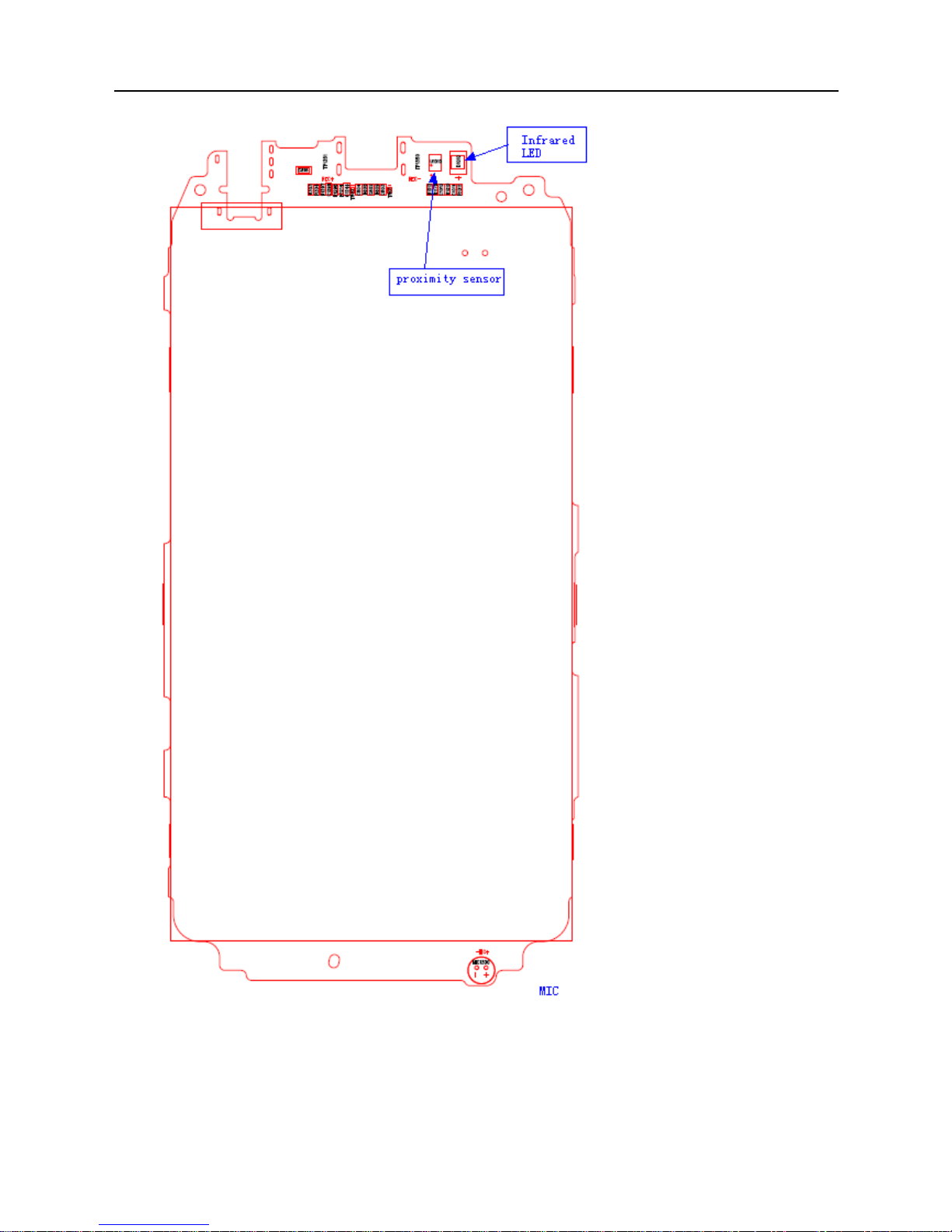
2.1 Description of main board component map .....................................................4
2.2 MT6589 circuit system.................................................................................6
2.3 Base band circuit .........................................................................................7
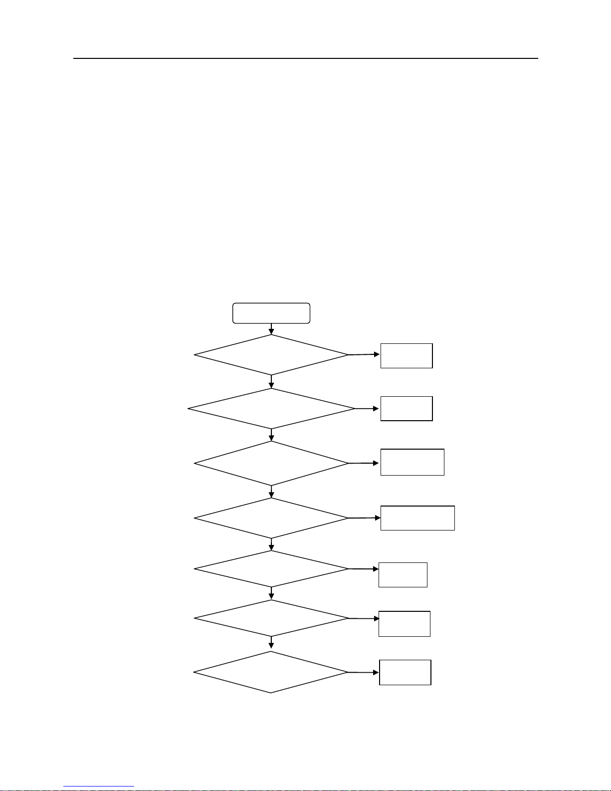
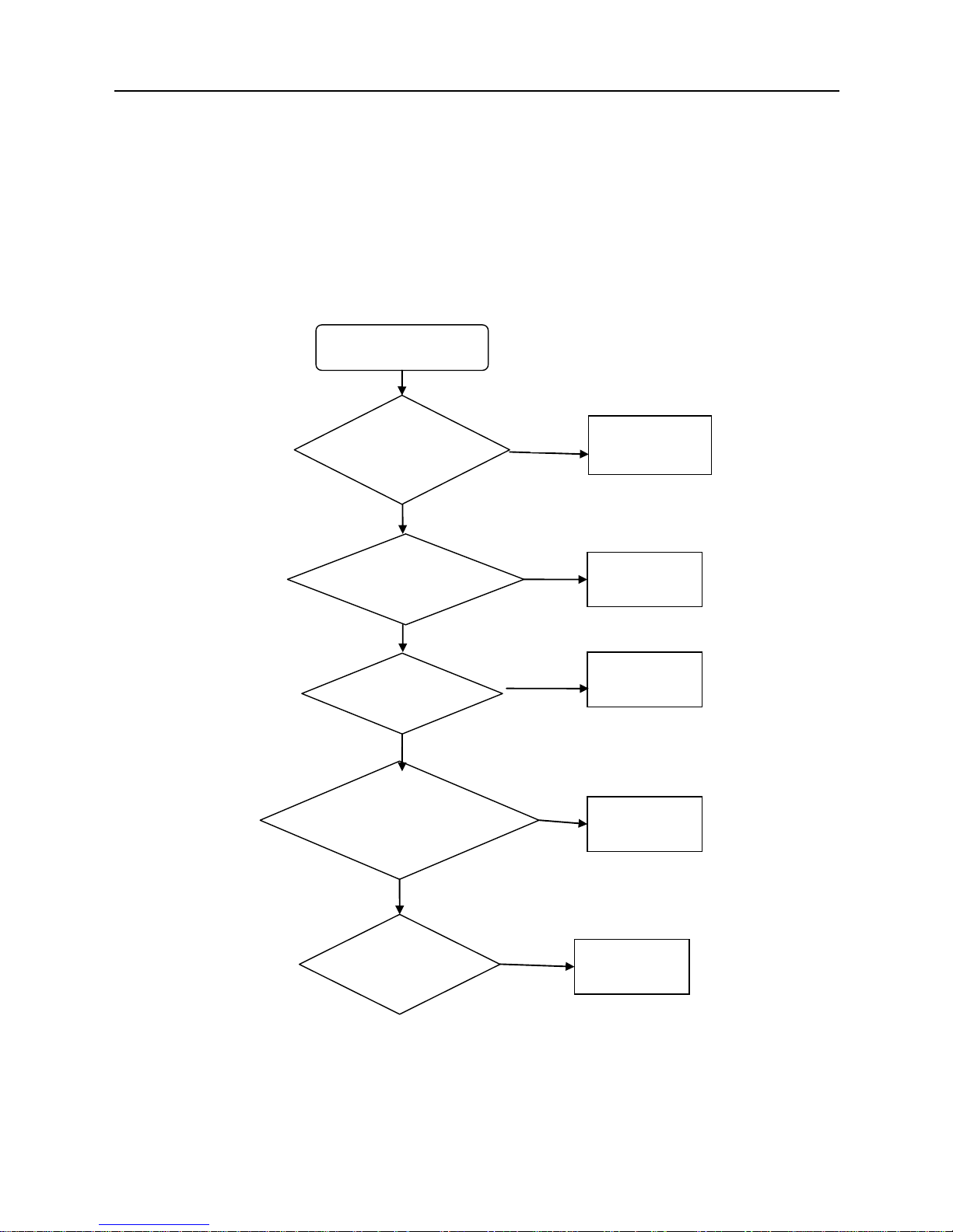
3. Trouble Shooting .............................................................................................8
3.1 Fail to startup/power on................................................................................8
3.2 Fail to charge ..............................................................................................9
3.3 Fail to display ...........................................................................................10
3.4 Fail to call................................................................................................. 11
3.5 Speaker no sound....................................................................................... 12
3.6 Earphone fail.............................................................................................13
3.7 Vibrator fail ..............................................................................................14
3.8 Side key fail..............................................................................................15
3.9 Failure to identify SIM card ........................................................................16
3.10 Camera fail ............................................................................................. 17
3.11 Failure to read T-flash card........................................................................18
4. BGA related GND or no function pad...............................................................19
4.1 CPU and memory pin map..........................................................................19
4.2 PMU pin map............................................................................................19
4.3 WIFI .......................................................................................................................20
4.4 TRANSEIVER.......................................................................................................20

1. Introduction
1.1 Objective
The manual is not a general publication but only edited for experienced technicians. The
main purpose is to provide the basic foundation for the electrical & mechanical
maintenance.
1.2 General Safety notice
1) Only an experienced technician can use this guide to repair the product while powered on.
Any maintenance by other non-technicians will cause serious damage of the handset.
Neither short circuit nor counter-polarity connection is allowed for any electronic part in the
handset.
2) Be careful of ESD protection during maintenance to avoid the damage of electrostatic
sensitive components on the handset.
3) If disassembling the handset is necessary for repair, please comply with the mechanical
structure disassembling work instruction. Otherwise, disassembling can damaged the
handset.
1.3 Use Instruction
1) Avoid using handset in conditions following:
Where there is any caustic liquid or gas
Where there is any high-temperature or fire circumstance
Where there is any flammable liquid or gas
2) Do not use handset while driving for your safety;
3) Please comply with corresponding rules in some special occasions (like in the confines
of an operating room or an airplane)
4) Accessory purchasing or changing should comply with model matching;
5) If cleaning the handset surface is needed, please use a cloth dipped in clean water. Do
not use soluble cleanser.

2. Technology summarize
2.1 Description of main board component map


2.2 MT6589 circuit system
MT6589M functional block diagram as following:
MD501 functional system is made of three parts as below:
Digital baseband function: Memory, LCM, GPIO interface, Keypad interface etc.
Analog baseband function: AUDIO(including MIC, Receiver, Speaker),Camera, Video,
Ambient light and Proximity sensor, Power management, RTC, Charge control, etc.
RF function: RF front-end module, Antenna, RF transceiver, GSM/WCDMA communication
system, etc.

2.3 Base band circuit
MT6589M baseband System Architecture as following:
Processing features:
◆High-performance ARM CORTEX A7 1.2GHz application processor :
1)ARM architecture v7
2)32 KB instruction and 32 KB data cache
3)8-stage In-order pipeline with dynamic branch prediction
4)Supports the ARM and Thumb instruction sets, and Jazelle technology to enable direct
execution of Java byte-codes

3. Trouble Shooting
3.1 Fail to startup/power on
The following conditions may cause boot fail: battery low, battery connector is damaged or
bad welding, components bad weld/short-circuit or damaged
First, change a fully charged battery test, still startup fail, check battery connector ok or not,
if connector damaged change a new one;
Second, connect to DC power supply, if the boot process is no current, we should check
power key solder ok or not;
Third, if the boot current is very small and cannot maintain ,connect the power on test point
to GND, then check below voltage in sequence, VPROC_PMU,VCORE_PMU,VM_PMU,
VRF18_PMU,VIO18_PMU,VIO28_PMU,VEMC_3V3_PMU,VEMC_1V8_PMU ok not.
Fourth, if the current stay in 40mA, we should check the circuit around flash, when CPU
calling program from flash fail, the current will stay in 40mA, re-download the software or
change a new flash or CPU.
Fail to power on
Check if the battery
is OK.
Change
battery
Check if battery
connects solder ok
Is power key OK?
Check each power
out of PMU
Resold
connect
Change a new
power key
Re-solder or
replace U2
Re-download
Software
OK
Y
N
N
N
N
Y
Y
Y
Y
OK
N
Y
N
Resold or replace
U1082
Resold or replace
U300
OK
Y

3.2 Fail to charge
Check charging circuit related component, check below information in sequence:
First, checks whether boot normal use the battery, if not check battery connector solder ok
or not;
Second, check USB connector on board solder ok or not;
Third, check T1110 whether reverse, check C1321resistance is very big or not, check
B1110,B1111 solder ok or not;
Fourth, check U2 solder ok or not, re-hot U2 or change a new one.
No charge
Check battery
can power on
normal or not?
Check battery
connector related
component
Check J1702
solder OK or not?
Check
T1110&C1321
Check B1110,B1111
and Q601 ok or not?
Change a new
one
Change T1110
or C1321
Change related
component
Check U2
Hot or change U2.
Y
N
N
N
N
N
Y
Y
Y

3.3 Fail to display
The screen dose not shines or shows white:
First, use DC power supply to start-up, check the board whether power on normal, ensure
main board can power on normal
Second, check LCD module, change a new module, check whether can display normal,
Third, check L1090, D1510 solder ok or not
Fourth, use oscilloscope to test LCD_BACKLIGHT_EN, check it whether high, if not, check
R1210 resistance, U300solder ok or not, re-hot U300or check a new one.
No display
Is the LCM well?
Change LCM
U1201
reverse or
damaged
L1090, D1510
NC or not
Change
U1201
Add L1090 or D1510
Change or
re-solder
U300
Change
U300
OK
N
Y
N
Y
N
Y
Y

3.4 Fail to call
When call with somebody, we cannot hear what he says or he cannot hear what we say:
This fail may cause by receiver or microphone fail, it can test in factory mode,
type“*#*#9375#*#*” enter factory mode, Transmitter/Receiver test, if ok, it may RF fail, if fail,
we need to make sure is receiver or microphone fail.
Call 112, if can hear voice, it may microphone problem, check microphone related
circuit ,check R801, R802, R808, R809 and T801,T802 solder ok or not, if all ok, change a
new microphone, also fail, check CPU, re-hot or change a new one.
Call 112, if cannot hear voice, it may receiver problem, change a new receiver, check R812,
R813 and C817,C818 ok or not, if ok, check CPU, re-hot or change a new one.
Voice sending or receiving no
function
Can hear sound in
Factory mode?
Check RF
Check
Receiver or
MIC
problem?
Hot or change
new one
Y
N
Receiver
Y
N
Y
Check
Related
R, C, TVS?
Check
U300?
Change
new
REC
Check a
new one
Rework
uncorrected
component
N
N
Hot or change
new one
Check
Related
R C TVS?
Check
U300?
Change
new MIC
Change a
new one
Rework
uncorrected
component
MIC
Y
N
N
Y
N
Y

3.5 Speaker no sound
First, check speaker ok or not, change a new one;
Second, check B1330、B1333、C1780、C1781、C1782, solder ok or not;
Third, check U2, re-hot or change a new one.
No sound
Is speaker OK?
Replace
Speaker
Are B1910, B1911
NC or not?
Check T1912,
T1913, C1929,
C1930, and C2001
ok or not?
Check U1001
ADD B1910,B1911
Re-solder uncorrected
component
Hot or change U1001
Y
N
Y
N
N
Y
N

3.6 Earphone fail
No sound in
earphone
Is earphone
connector OK?
Replace
earphone
Is J601 soldering
well?
Are All TVS right
direction?
Related R,
C right?
Re-solder J601
Re-solder uncorrected
TVS
Re-solder
uncorrected R C
Y
N
N
N
Y
Y
N
Hot or
change
U300
OK
Y

3.7 Vibrator fail
Motor doesn’t work
Supply 3.3V for motor,
test motor can work or
not
Change a
new Motor
Check related R, C OK
or NOT, Check D1401
reverses or not
Hot U2 or Change a
new one
Change uncorrected
component
OK
Y
N
N
Y

3.8 Side key fail
Side key no function
Is key switch soldering
OK?
Re-solder or
change new
one
Is R1775, R1776 and
R1777, NC or not?
Check U2
Solder 1K resistance
Re-sold or change U2
Y
N
Y
N
Y

3.9 Failure to identify SIM card
SIM is not identified
Touch Pin is
clean?
Clean SIM socket
Change a new
SIM to try
Is SIM socket
good?
SIM is damaged.
Replace it
Change a new one.
Check if VSIM1/
VSIM2 are OK?
Change U2
N
Y
N
N
Y
Y
Y
Check each signal
on SIM is OK?
Hot U2r change a
new one
N
N

3.10 Camera fail
First, change a new camera module, check camera connector ok or not;
Second, check AVDD, DOVDD, if fail check J1400
Third, use oscilloscope to test I2C, CAM_RST, CAM_MCLK, CAM_PCLK, MIPI_DATA,
and MIPI_CLK. If signals abnormal check U300, re-hot or change a new one.
Camera fail
Is camera connector
soldering well?
Re-solder or
change new
one
Check camera ok or
not?
Check AVDD
DOVDD ok or
not?
Check each signal
of Camera is ok or
not?
Change a new
camera
Check R1409
component
Hot U300 or
change a new one
Y
N
N
N
Y
Y
N

3.11 Failure to read T-flash card
First, change another T flash card, check whether T flash card bad or not
Second, check card connector solder ok or not, if fail, re-solder or change a new one
Third, check TVS reserved or not, check VDD whether normal
Fourth, test related signals, such as MCCK, MCCM0, MCDA0, MCDA1…MCDA3, if
abnormal, check U300, re-hot or change a new one.
T-F Card is not
identified
Change a new
TF-card to test
T-F card is
damaged. Replace
it
Check T flash
card socket
ok or not?
Check TVS
reverse or not?
Re-solder it or
change new one
Solder it correct
Check VDD
OK or not?
Hot U2 or
change new
one
Y
N
N
N
Y
Y
N
Check each
signal OK or not?
Hot U300
or change
new one
N
N

4. BGA related GND or no function pad
Red--------no function pad
White------GND pad
4.1 CPU and memory pin map
4.2 PMU pin map

4.3 WIFI
4.4 TRANSEIVER
Other manuals for DASH 4.5
2
Table of contents
Other Blu Cell Phone manuals