SAT-9/TD-900 Installation and Programming Guide
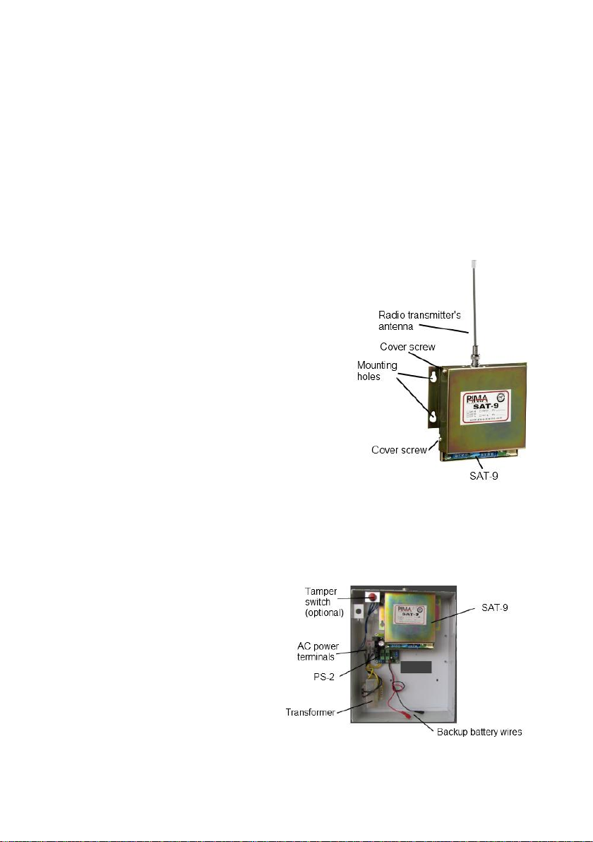
1.3. The SAT-9 main features
Two operating modes:
As main communicator: All events are transmitted via RF;
As PSTN backup: Events are transmitted in case of a PSTN problem;
Supports variety of protocols:
Input Protocols (from dialer): Contact ID, Pulse, and DTMF;
Output Protocols (RF to CMS): PID, PAF™ / NPAF™, Intrac 2000 and Milcol-D;
Accounts from panel or internal programmed accounts:
If an account number is not programmed, the SAT-9 uses the account number
received from the control panel;
Supports two frequencies: Each frequency can use a different format
Control:
PGM input: Selects if SAT-9 functions as backup or main communication channel;
PSTN monitoring: Performs line check and line interception (with pre-programmed
phone number);
Transmission LED: Turned ON when SAT-9 is transmitting data;
Auto Test Mode: Periodic transmission test as programmed;
Manual Test Mode: Manual transmission test with a TEST button;
1.4. Benefits
Easy installation and maintenance: the SAT-9 is fully programmable in the field
by a laptop with the COMAX application and a DPU adapter. Parameters that
can be programmed:
Which transmitter frequency for which PSTN format;
Radio format;
Account number;
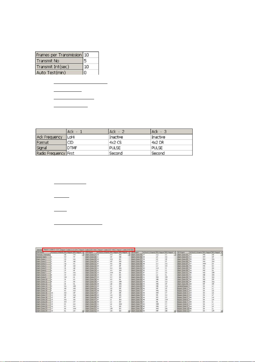
No. of Frames per transmission;
Transmission intervals;
Auto test intervals;
Three ACK protocols and frequencies;
Report codes for all telephone events;
Frequency load balance: the two frequencies of the installed VHF/UHF
transmitter can be fully utilized by the SAT-9.
Watchdog;
Surge and ESD protection.