2
Warnings and Agreements
Welcome! The PinPAC Pinball Person Audio
Controller has been designed for simplicity of
installation! As with any Pinball Machine
modification and add on kit there is a required level
of expertise for the installation. If you are not
proficient in basic pinball parts installation we
recommend having our kit installed by someone who
is proficient with the basics of pinball repair.
Pinnovators requires our kit be installed by an
experienced Pinball service technician with basic
electrical skills. As with any electrical piece of
equipment a danger does exist and you must agree
to not hold Pinnovators responsible for any injury,
damages, etc. before continuing.
Sound Levels: Pinnovators recommends running
your headphone sound level at a safe level to
prevent long term hearing loss. For a good example
of recommend sound levels, we recommend
following suggestions given by major audio
equipment manufacturers such as Apple and their
Ipod.
phys.org/news80304823.html
www.macworld.com/article/1060274/hearingprotection.html
ESD: We recommend always discharging the
headphone cable by touching it to an exposed metal
part of the pinball machine before plugging it into
the machine.
Power Cord: ALWAYS UNPLUG THE POWER CORD
for safety when working on your pinball machine!
Playfield Propping: Pinnovators highly advises
following Playfield propping instruction for your
pinball machine. These instructions are typically
found inside the Operators manual for each
machine. Failure to follow these instructions can
cause fatal injuries or even Death. Pinnovators also
recommends having an assistant hold a propped
playfield in the up position when servicing under the
playfield.
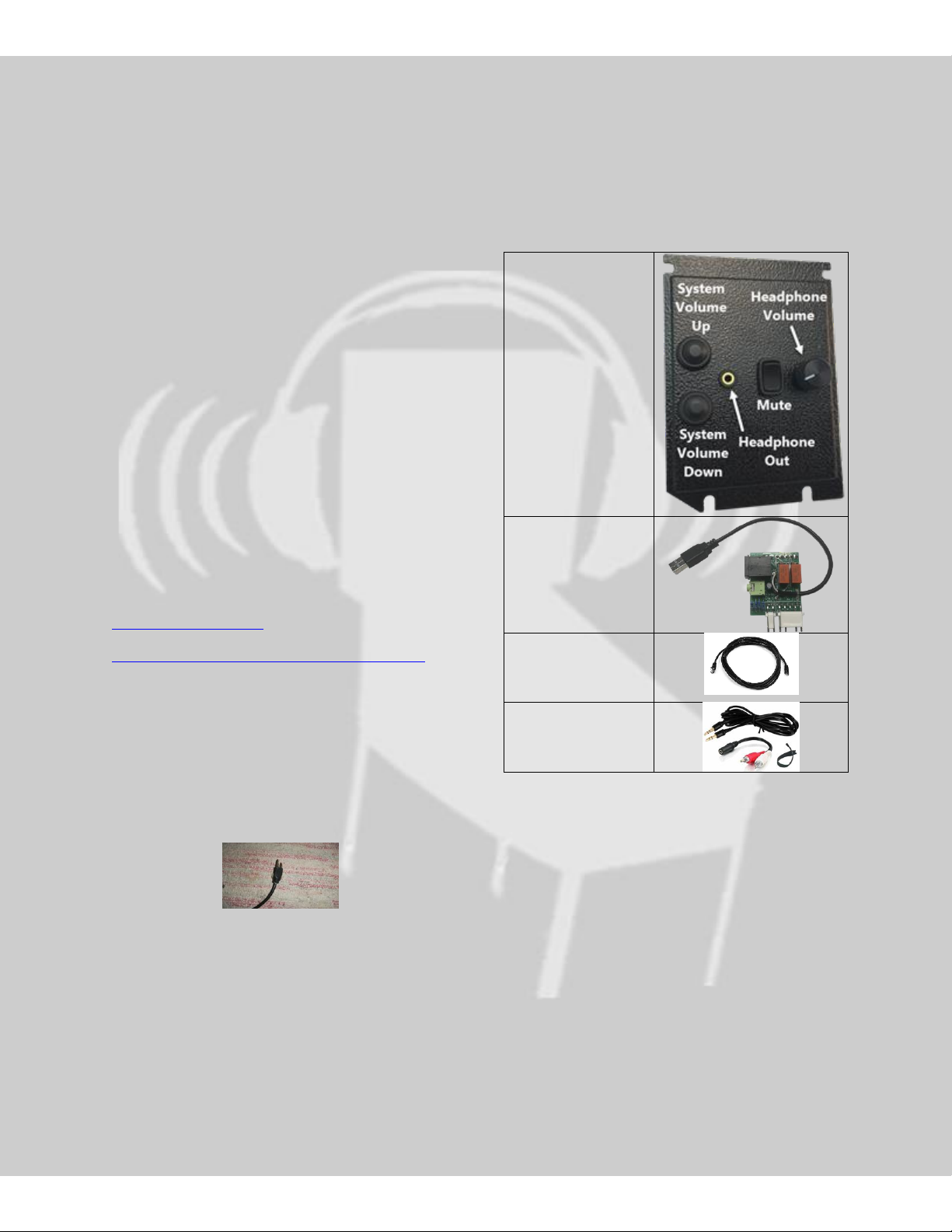
1. What’s included in the
PinPAC4 Kit