Pintek PW-7033 User manual
INSTRUCTION MANUAL
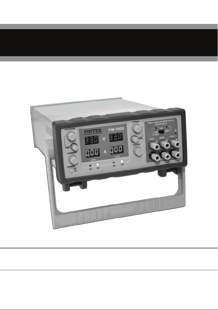
Triple Output 200VA DC Power Supply
P
W
-7033

1

2
TABLEOFCONTENTS
NOTICE BEFORE OPERATION………………………………………………3
1. Unpack the instrument……………………………………………………...3
2. Environments………………………………………………………………..3
3. Check the Line Voltage……………………………………………………..3
4. Hints for operation……………………………………………………..3
MAINTENANCE…………………………………………………………………5
GENERAL MAINTENANCE……………………………………………………5
FUSE REPLACEMENT………………………………………………………..5
SPECIFICATIONS……………………………………………………………6
FRONT PANEL DESCRIPTION………………………………………………7
REAR PANEL DESCRIPTION……….…………………………………….10
OPERATION INSTRUCTION………………………………………………11
1. Independent Mode…………………………………..………………….11
2. Serial Tracking Mode…………………………………………………….11
3. Parallel tracking Mode…………………………………………………….12
4. Serial mode………………………………………………………………12
5. Parallel Mode………………………………………………………………13
6. Fixed 5V/3A output………………………………………………………13
3
NOTICEBEFOREOPERATION
1. Unpack the instrument:
After receipt of the instrument, immediately unpack and inspect it for
any damage which might have been sustained when in transportation or
shortage of accessories. If any sign of damage and shortage of
accessories are found, immediately notify the dealer.
2. Environments:
Normally, operational temperature of the instrument is 10°C to 40°C
90%R.H.
(50°F to 104°F). Operation of the instrument outside of this temperature
range may cause damage to the circuits.
3. Check the Line Voltage:
The instrument can operate on any one of the line voltages when in the
below table by inserting the line voltage selector plug in the
corresponding position on the rear panel.
Before connection the power plug to an AC line outlet, be sure to check
that voltage selector plug is set in the correct position corresponding to
the line voltage.
Selector Line Voltage Fuse
115V 100~125V 50/60Hz 6A
230V 220~240V 50/60Hz 3A
4. Hints for operation:
(1) Never place heavy objects on the instrument.
(2) Never place a hot soldering iron on or near the instrument.
(3) Never insert wires, pins or other metal object into ventilation fan.
(4) Never move or pull the instrument with power cord or output lead,
especially never move instrument when power cord or output lead is
connected.
(5) If the instrument is used in a manner not specified by the manufacturer,
the protection provide by the equipment may be impaired.

4
WARNING!
The following precautions must be observed to help prevent electric
shock.
1. When the instrument is use to make testing. There is always a certain
amount of danger from electrical shock. The person using the
instrument in such condition should be a qualified electronics technician
or otherwise trained and qualified to work in such circumstance.
2. Do not operate the instrument with the cover removed unless you are a
qualified service technician.
3. The ground wire of the 3-wire AC power plug places the chassis and
housing of the instrument at earth ground. Use only a 3-wire outlet, and
do not attempt to defeat the ground wire connection or float the
instrument to do so may pose a great safety hazard.
4. Do not obstruct the ventilation holes in the rear panel. As this will
increase the internal temperature.
5. Never apply external voltage to the output terminal of the instrument.
6. The instrument is designed for INDOOR USE ONLY.
7. This instrument has been evaluated to INSTALLTION CATEGORY II,
POLLUTION DEGREE 2.

5
MAINTENANCE
GENERAL MAINTENANCE:
1. Preventive maintenance:
Clean and recalibrate the instrument on a regular basis to keep the
instrument looking nice and working will.
2. Cleaning:
Remove any dirt, dust and grime whenever they become noticeable on
the outside cover with a soft cloth moistened with a mild cleaning
solution.
3. Servicing:
If the instrument ever becomes inoperative or damaged, refer servicing
to a qualified repair facility.
FUSE REPLACEMENT:
If the fuse blows, the LED will not light and the instrument will not operate.
Replace only with the correct value fuse. The fuse is located on the rear
panel adjacent to the power cord receptacle. Remove the fuse holder
assembly as follows:
1. Unplug the power cord from rear of the instrument.
2. Insert a small screwdriver in fuse holder slot (located between fuse
holder and receptacle). The fuse holder away from receptacle.
3. When reinstalling fuse holder, be sure that the fuse is installed so that
the correct line voltage is selected.
6
SPECIFICATIONS
ITEM PW-7033
Power Transformer E.I. Type Transformer
Max. Continual Output Power 207 VA
Max. Raised Temperature < 45 °C
Independent Output 0~32V / 0~3A x 2, 5V Fixed / 0~3A
Constant Voltage Characteristic
Regulation Line < 0.01% + 3mV, Load < 0.01% + 5mv
Ripple & Noise < 0.4 mVrms
Temperature Coefficient < 300 PPM/°C
Constant Current Characteristic
Regulation Line < 0.2% + 2mA, Load < 0.2% + 3mA
Ripple & Noise < 2.5 mArms
5V Fixed Output
Regulation Line Regulation < 5mV, Load Regulation < 10mV
Ripple & Noise < 1.5mVrms
Voltage Accuracy 5V ± 0.25V
Max. Output Current 3A
Tracking Operation
Parallel Regulation Line < 0.01% + 3mV, Load < 0.01 + 5mV
Series+and-Supply Regulation Line < 0.01% + 3mV, Load < 0.01 + 5mV
Slave tracking error < 0.5%+2 digital of the master
Series Single Supply Regulation Line < 0.01% + 5mA, Load Regulation < 300mV
Display
Voltage 3 Digits 0.36" Green LED
Current 3 Digits 0.36" Red LED
Accuracy 0.1% + 2 digits
General
Power Source ACV 115/230 ± 10%, 50/60Hz
Dimensions( W x H x D) 255 x 120 x 380 mm
Weight 7.9kg
7
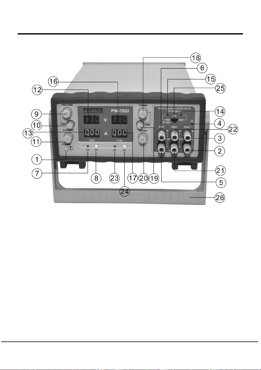
FRONTPANELDESCRIPTION
○
1Power switch:
Push the switch button to turn "ON" the power and the LED(12,13,16,17)
will light up ; to push the button again, the power will turn "OFF" .
○
2CH3/5V output terminal:
Negative output terminal of the fixed 5V/3A output (black).
○
3CH3/5V output terminal:
Positive output terminal of the fixed 5V/3A output (red).
○
4CH3/Over load indicator:
5V/3A over load red LED indicator.

8
○
5CH1 output terminal:
Negative output terminal of the CH1 0~32A/0-3A output (black).
○
6CH1 output terminal:
Positive output terminal of the CH1 0~32A/0-3A output (red).
○
7CH1 C.C. mode LED:
Red LED to indicate constant current.
○
8CH1 C.V. mode LED:
Green LED to indicate constant voltage.
○
9CH1 voltage adjustment knob and PAR/SER mode.
○
10 CH1 voltage fine adjustment knob.
○
11 CH1 current adjustment knob and PAR/SER mode.
○
12 CH1 voltage indicator display in full 3-digits Green 0.36"LED.
○
13 CH1 current indicator display in full 3-digits Red 0.36" LED.
○
14 Series mode indicator:
When switch is set the power supply in series mode, the Green LED will
be light to indicate series mode.
○
15 Parallel mode indicator:
When pull switch is set the power supply in parallel Mode the Red LED
will be light to indicate parallel mode.
○
16 Slave voltage indicator display in full 3 digits Green 0.36"LED.
○
17 Slave current indicator display in full 3 digits Red 0.36"LED.
○
18 CH2 voltage adjustment knob:
For adjusting CH2 output voltage when CH2 is at C.V. Mode.
○
19 CH2 voltage fine adjustment knob.
○
20 CH2 current adjustment knob:
For adjusting slave output current when slave is at C.C. Mode.
○
21 CH2 output terminal:
CH2 negative output terminal 0-32V/0-3A output (black).

9
○
22 CH2 output terminal:
CH2 positive output terminal 0-32V/0-3A output (Red).
○
23 CH2 C.C. mode indicator:
Red LED is indicated constant current at CH2 power.
○
24 CH2 C.V. mode indicator:
Green LED is indicated constant voltage at CH2 power.
○
25 Output mode switch:
Select to set the "IND", "SER", "PAR" position to turn "Independent" or
"Serial Tracking" or "Parallel" output mode.
○
26 Portable carry.
10
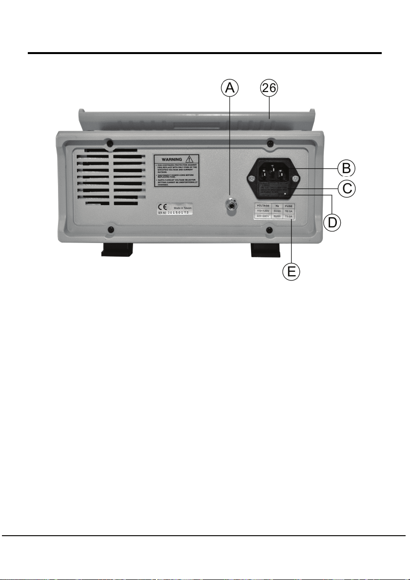
REAR PANEL DESCRIPTION
○
AGND terminal.
○
BPower input socket.
○
CFuse Holder and input voltage selector:
The selected input voltage is set the voltage marked on the holder to the
▽mark on the rear panel.
○
DThe input power voltage indicator:
The ▽mark show the input line voltage is set.
○
EThe fuse table is for input voltage.

11
OPERATIONINSTRUCTION
The power supply 7033 can be operated alone or connected two or more
units in serial to obtain a higher voltage rating (Max. 240V) or in parallel to
obtain a higher current (Max. 24A).
WARNING!
Never connected GND (○
A) terminal to any place on this operation.
1. Independent Mode:
The CH1 and the CH2 output of 7033 can be used independently to
generate voltage and current.
To operate 7033 under independent mode. Set the CH1 output
voltage/current and CH2 output voltage/current as described in section
A and B.
2. Serial Tracking Mode:
[NOTE] When 7033 is operated under this mode. The CH1 output is
serial connected to the CH2 output automatically. The serial output is
generated from the "+" of the CH1 output terminal (○
6) and the "-" of
the CH2 output terminal (○
21 ). The output voltage will be TWICE of the
set CH1 output voltage and the current will be the same as the CH1
setting current.
2-1. The CH1 voltage adjustment knob (○
9) the power supply 7033 will
under serial operation mode and the green LED (○
14 ) will light up.
2-2. Turn the CH2 current adjustment knob (○20) clockwise to maximum.
2-3. Set the CH1 output voltage and current as described on section A.
2-4.The output terminal will be "+" of the master and "-" of the slave
terminals.

12
3. Parallel tracking Mode:
[NOTE] When 7033 is operated under "PARALLEL" mode. The CH1
output terminals are parallel connected to the CH2 output terminal
automatically. The parallel output is generated from the CH1 output for
both "+" and "-" terminals (or CH2 output terminal) the output voltage is
the same as the CH1 set value and the output current is twice the set
CH1 output current.
3-1. "PULL" the current adjustment knob of the CH1 output (○
11 ) to set
the 7033 operate under parallel mode and the green LED (○
14 ) will
light up.
[NOTE]
Output mode switch can be adjusted at the “IND”, “SER”, or “PAR”
position.
3-2. Set the CH1 output voltage and current.
3-3. The output terminal can be the "+","-" terminal the CH1 output,
maximum to 6A.
4. Serial mode:
The power supply 7033 can be connected two or more units in series to
obtain a higher voltage output (Max. 240V).
4-1. Set all the 7033 which would be connected in serial operation under
serial tracking mode as described on section 2, serial tracking
mode and adjusts to the same output.
4-2. Connect the "-" CH2 output terminal of the unit 1 to the "+" CH1
output terminal of the unit 2.
4-3. The output voltage the system will be the "+" CH1 output terminal of
the unit 1 and the "-" CH2 output terminal of the unit 2.

13
4-4. If the connected units are more than 2. Connect the "+" CH1 output
terminal of the 3rd unit to the "-" CH2 output terminal of the unit 2.
etc. The output voltage of the system will be the "+" CH1 output
terminal of the 1st unit to the "-" CH2 output terminal of the last
unit.
WARNING!
The maximum output voltage of the system is never exceeds 240V.
5. Parallel Mode:
The power supply 7033 can be connected two or more units in parallel
to obtain a higher current output (Max. 24A only).
5-1. Set all the 7033 which will be connected in parallel operation under
parallel tracking mode as described on section 3, parallel tracking
mode and adjust all units to the same output voltage
5-2. Parallel connected the "+" CH1 output of all unit and "-" CH2
output of all units in the system.
5-3. The output voltage of the system is the same as the units been set.
The output current of the system is the sum of each unit.
5-4 Output is only at CH2, Maximum to 6A.
WARNING!
The Max. output current of the system never exceeds 24A.
6. Fixed 5V/3A output:
This is the standard 5V/3A-power output for use by TTL logic circuit.
When the load exceed 3A, the red overload LED will light up. The output
voltage will be lower and the power supply will be under C.C. mode.

14

15
TINSE07 Ver.00
Made In Taiwan
Table of contents
Other Pintek Power Supply manuals


