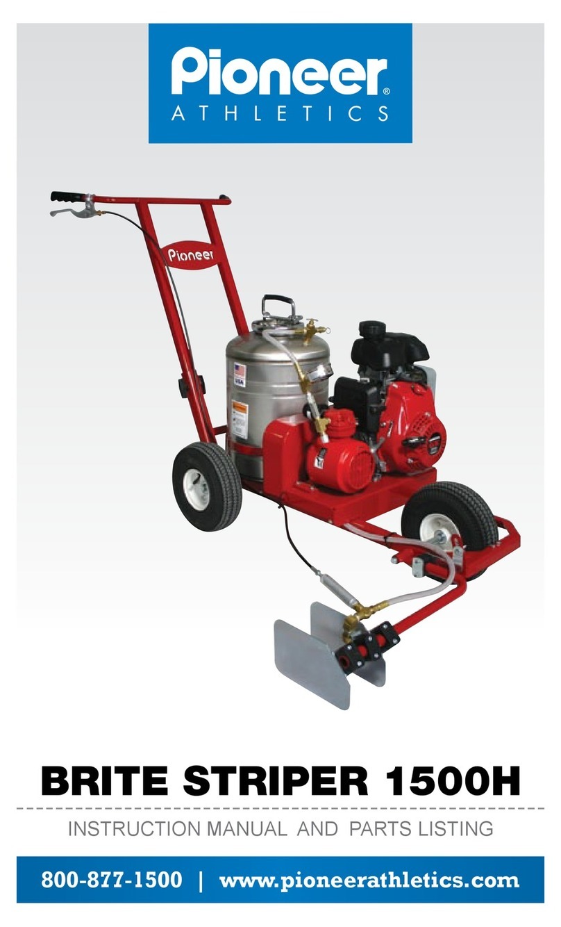
Pioneer Athletics BRITE STRIPER 1600PS Troubleshooting guide

INSTRUCTION MANUAL AND PARTS LISTING
BRITE STRIPER®1600PS
800-877-1500 | www.pioneerathletics.com

Follow us on Twitter!
www.twitter.com/pioneerathletic
Become a Facebook Fan!
www.facebook.com/pioneerathletics
Check out our Blog!
www.pioneerathletics.com/blog
Phone: 800-877-1500
Fax: 800-877-1511
www.pioneerathletics.com
4529 Industrial Parkway
Cleveland, OH 44135
Looking for more
information to help
you stripe your field?
Check out our website:
pioneerathletics.com
to find the following
helpful resources:
Pioneer Athletics
Blog discussing the
tips, tricks, technology,
research, tradeshows,
and updates in the
athletic field painting
and maintenance
industry.
Athletic Field
Layouts for football,
baseball, softball,
soccer, rugby, lacrosse,
tennis, basketball, field
hockey, volleyball,
and track & field
Videos of how-to’s and
product demonstrations
MSDS for Pioneer
products
Special Offers
sign-up online to receive
product specials and
industry updates
And Much More!
2
Nozzle Tips
2
Nozzle Screens
2
Nozzle Caps
1
Tank Gasket
1
Pump Repair Kit
1
Safety Relief Valve
1
Drive Belt
1
Spark Plug
1
Air Filter
As a convenient accessory,
Pioneer has created a Special
Tune-Up Kit for the Brite
Striper®1600PS that includes:
Congratulations on your
purchase of a new Brite
Striper®1600PS!
For product updates, athletic field
striping tips, and maintenance
tips, register your new field
marking machine at:
pioneerathletics.com/register
or: 800-877-1500

TABLE OF CONTENTS 1
Brite Striper®1600PS
Assembly Instructions
Removing from Shipping Carton ........................................................ 2
Handle Assembly ............................................................................... 2
Tools Necessary for Assembly ........................................................... 3
Adjustable Spray Box ...................................................................... 2-3
Operation & Care
Before Starting ................................................................................... 4
Care and Operation of Compressor ................................................... 5
Care and Operation of Paint Tank Unit............................................ 5-6
Paint Tank Label................................................................................. 6
Operation of Machine......................................................................... 7
Striping Tips ..................................................................................... 10
Clean-up of the Paint Tank Unit.................................................... 11-12
Clean-Up Tips .................................................................................. 12
How to Store..................................................................................... 12
Normal Wear .................................................................................... 12
Customer Service ............................................................................ 15
Shipping the Product........................................................................ 15
Trouble Shooting & Parts
Parts List & Parts Explosion Drawing.............................................. 8-9
Trouble Shooting ......................................................................... 13-14
Limited Warranty Information ........................................................... 16

ASSEMBLY 2
WARNING: ENGINE IS NOT SHIPPED WITH MOTOR OIL.
If you have any questions concerning assembly or
operation, please call our CUSTOMER
SERVICE DEPARTMENT at: 800.877.1500
Assembly Instructions for Brite Striper®1600PS:
Remove Brite Striper®1600PS – two people necessary to lift
1. Remove handle bar
2. Remove box containing:
a) 12 Ft. Hand Hose Assembly
b) Spray Box Assembly
c) Drain Line
d) Shut-Off Valve Assembly
Assemble handle:
Parts required:
1. Handle
2. Handle adjustment bolts
a) Slide handle into frame
b) Insert handle adjustment bolts at desired height
Adjustable Spray Box:
Parts Required:
2 - 3/4” x 1/4” - 7/16” Hex Head Bolts
2 - 7/16” Hex Head Self-Locking Nuts
1 - Snap Ring
1 - Adjustable Spray Box

ASSEMBLY 3
Adjustable Spray Box Continued:
Tools Required:
7/16” Socket and Ratchet
7/16” Open End Wrench
5/8” Open End Wrench
Snap Ring Pliers or Screwdriver
Hex Key Wrenches
1. Slide Adjustable Spray Box Bar on front axle. Align holes on Spray
Box Support Bracket with holes on the front of the frame. Insert 2
hex head bolts from top of Spray Box Support Bracket and attach
self-locking nuts from bottom of frame and tighten completely. Attach
Snap Ring on end of axle to prevent Spray Box Bar from sliding off.
A. Installation Instructions for the Tip Shut-Off Upgrade Kit (Item#
1640). All adjustments are preset, use thread sealant on all
exposed threads:
B. Screw on nozzle assembly onto shut-off valve, tighten to angle
shown in picture below.
2. Re-attach nozzle to spray arm, hose to bottom of paint tank and
install control lever on handle. Use cable ties when needed.
3. Attach free end of paintline hose to shut-off valve on Adjustable
Spray Box and tighten with 5/8” open end wrench. DO NOT
OVER-TIGHTEN. MAKE SURE THE NOZZLE TIP IS ALIGNED
HORIZONTALLY WITH THE GROUND.
4. Use hex key wrenches to adjust side plates for proper width. Adjust
bar length by unscrewing the wing nut and setting desired height.
Tighten wing nut to secure new position. Side plates may need to
be adjusted up or down depending on the height of spray box bar.
Do not over-tighten side plates. SIDE PLATES SHOULD BE ABLE TO
MOVE UP AND DOWN BY HAND.

BEFORE STARTING 4
The Brite Striper®1600PS is shipped WITHOUT ENGINE OIL.Be sure
to check the enclosed operating and maintenance instructions for
proper oil. Follow lling directions.
1. Carefully read and follow instructions for starting and maintaining
the engine (in a separate booklet furnished with your machine).
2. Check all hose connections and ttings making sure they are tight.
3. Be sure paint tank pump assembly is sealed tightly. Refer to care
and operation of tank unit section.
4. Check to make certain that paint tank is secured tightly.
5. Any ttings, if replaced, should have teon tape applied before
tightening. Do not force ttings on paint tank bushings. Always
hold nut on paint tank bushing when tightening ttings.
DO NOT TIGHTEN FITTINGS WITH PRESSURE IN THE TANK.

CARE AND OPERATION 5
Care and Operation of Compressor:
The piston-type compressor requires minimal maintenance.
Pre-lubricated ball bearings provide for delivery of oil free air.
APPLYING OIL TO ANY PART CAN RESULT IN REDUCED
PERFORMANCE AND MAY VOID WARRANTY.
The compressor is designed to release pressure at approximately
40 to 45 PSI. If it is not releasing, contact us immediately. You may
have a defective or damaged relief valve.
The air lter should be replaced whenever it becomes dirty or clogged.
OPERATE COMPRESSOR AT LOWEST ENGINE SPEED PRACTICAL.
Care and Operation of Paint Tank Unit:
1. Remove pump assembly by raising locking lever to vertical
position, and turning counter-clockwise until ends of locking lever
reach slots in locking ring; lift out.
2. Mix paint (in pail - not in tank) and strain through cloth or ne sieve.
Paint strainers packaged 25 per case are available. Use item #PS
25 when ordering.
3. Fill tank 3/4 full, leaving remaining space for compressed air.
4. Replace pump assembly in tank, holding locking lever in vertical
position, turn clockwise about half way and push locking lever
down to seal. Do not force.
NEVER USE TOOLS TO TIGHTEN PUMP ASSEMBLY.
5. Optional method of pressurizing paint tank: Build pressure by
using handle of the pump assembly. Pump plunger up and
down until sufcient pressure builds and spray becomes ne;
re-engage pump handle by pushing down against spring and
turning back into retaining slots.
Continued on next page.

CARE AND OPERATION 6
Care and Operation of Paint Tank Unit Continued:
WARNING:
RELEASE PRESSURE WITH PRESSURE RELEASE VALVE WHEN
NOT IN USE. NEVER USE ANY TOOL TO REMOVE PUMP IF
THERE IS PRESSURE IN THE TANK. FAILURE TO FOLLOW THIS
INSTRUCTION MAY RESULT IN PERSONAL INJURY OR DAMAGE.
NEVER STAND WITH HEAD OR BODY OVER TOP OF TANK WHEN
OPERATING OR REMOVING PUMP. FAILURE TO FOLLOW THIS
INSTRUCTION MAY RESULT IN PERSONAL INJURY.
PERIODICALLY TEST HOSE FOR STRENGTH AND MAKE SURE
ALL FITTINGS ARE SECURE. REPLACE WORN HOSE WITH
RECOMMENDED REPLACEMENT PARTS (REFER TO PARTS LIST).
WE RECOMMEND THE USE OF GOGGLES WHEN SPRAYING.
FAILURE TO FOLLOW THIS INSTRUCTION MAY RESULT IN
PERSONAL INJURY.
Paint Tank Label:
WARNING: IMPROPER USE OR FAILURE TO FOLLOW INSTRUCTIONS CAN
RESULT IN EXPLOSIVE FAILURE WITH MAJOR INJURIES. FOR SAFE USE
OF THIS PRODUCT—YOU MUST READ AND FOLLOW ALL INSTRUCTIONS
BEFORE USE.
CAUTION: Do not leave a pressurized sprayer in the hot sun. Heat
can cause pressure build-up. Do not store or leave solution in tank
after use. Always wear goggles, gloves, long sleeve shirt, long pants
and full foot protection when spraying. Never use any tool to remove
pump if there is pressure in sprayer. Never stand with face or body
over top of tank when pumping or loosening pump to prevent ejected
pump assembly and/or solution from striking and injuring you. Never
pressurize sprayer by any means other than the original pump. Do
not attempt to modify or repair this product except with original man-
ufacturer’s parts. NEVER SPRAY FLAMMABLE MATERIALS OR PRESSURE
AND GAS PRODUCING CHEMICALS SUCH AS SODIUM HYDROXIDE. ALWAYS
READ CHEMICAL LABEL BEFORE FILLING SPRAYER AS SOME CHEMICALS
MAY BE HAZARDOUS WHEN USED WITH THIS SPRAYER. PRE-USE CHECK:
Remove pump (see filling, pressurizing and spraying instructions),
inspect interior and exterior of tank for signs of deterioration (i.e.
rust, bubbling,and/or pitting) of body and bottom. Any sign of de-
terioration indicates possible tank weakening and could result in
explosive bursting under pressure. If any of these signs are found,
discard tank immediately and replace. Do not attempt to patch leaks,
etc., as this could result in serious injury. Follow filling, pressuriz-
ing and spraying instructions EXCEPT: Use water only. Pump plunger
only 8-10 strokes and inspect for leaks. Open discharge to make
sure it is not clogged. If unit passes this test, release pressure (see
pressure releasing instructions), empty tank, and proceed with fill-
ing, pressurizing and spraying instructions. FILLING, PRESSURIZING
AND SPRAYING INSTRUCTIONS: To engage handle in lock position: Push
handle down to completely compress spring and rotate handle 1/4
turn, then allow handle to raise into the lock position. To remove
pump from: FUNNEL TOP STYLE: Engage handle in locked position and
turn pump counterclockwise until pump can be removed from tank.
3-PRONG CLAMP OPEN HEAD STYLE: Turn handle counterclockwise until
3-prong clamp is loose. Then rotate clamp counterclockwise to stop
and lift pump out. LOCKING LEVER OPEN HEAD STYLE: Engage handle in
locking hooks then lift locking lever to its most upright position. Turn
pump counterclockwise until prongs are located under slots in funnel
and lift pump out. THREAD CAP STYLE: Engage handle in lock position
and turn pump counterclockwise until pump can be removed from
tank. Prepare spray solution following directions on chemical con-
tainer label. Strain solution and fill tank to indicated usable capacity,
leaving remaining space for compressed air. To close after lling:
NOTE: Check pump barrel to be sure no dirt or grass is stuck to barrel.
FUNNEL TOP STYLE: By placing pump into tank opening and rotating
clockwise until tightly locked and sealed in tank opening. 3-PRONG
CLAMP STYLE OPEN HEAD: Place pump prongs down into slots in fun-
nel. Turn clamp clockwise to furthest position under bottom slot, then
turn handle clockwise until tightly locked and sealed in place. LOCK-
ING LEVER OPEN HEAD STYLE: Lift locking lever into upright position.
Place pump prongs into slots in funnel. Turn pump clockwise until
it stops, then push locking lever down to funnel to lock and seal in
place. THREAD CAP STYLE: Place pump into tank opening then rotate
clockwise until tightly locked and sealed in tank opening. To pressur-
ize sprayer disengage handle from locked position, push down, turning
1/4 turn to release handle and then pump plunger up and down until
it works hard. Refer to filling, pressurizing and spraying instructions:
To engage handle in lock position.
WARNING: THIS SPRAYER IS NOW UNDER PRESSURE AND DANGEROUS.
Always wear goggles, gloves, long sleeve shirt, long pants and
sturdy foot protection when spraying. Re-pump unit as required to
maintain spray force.
PRESSURE RELEASE INSTRUCTIONS: WARNING: To avoid possibility of
ejected pump assembly and/or spray material from striking and in-
juring you: Place unit on its side with top directed away from you with
outlet on top, open discharge and allow remaining spray solution
and pressure to be completely exhausted. Turn sprayer upright, then
remove pump (follow filling, pressurizing and spraying instructions),
while maintaining position of top of sprayer away from you.
SPRAYER CARE, STORAGE AND MAINTENANCE: Clean tank and dis-
charge thoroughly. Remove pump and empty sprayer. Sprayer tank
should be hung upside down, with pump removed, in a warm dry
location. Pump should be periodically oiled by dropping 10-12 drops
of light oil down pump rod through opening in cover. At least twice
a year and always before storage, remove pump barrel from cover
assembly, apply a small amount of vaseline or other similar lubricant
to barrel threads and assemble (if applicable). SK-637-5 R0500

OPERATION OF MACHINE 7
1. Check to make certain that brass bleed-off valve
(located on cross tting) is in closed position so air will not escape.
2. Make certain that your V-belt is tight.
WARNING: NEVER OPERATE UNIT WITHOUT BELT GUARD IN
PLACE. FAILURE TO FOLLOW THESE INSTRUCTIONS MAY RESULT
IN PERSONAL INJURY OR DAMAGE.
3. Test run the machine with water to see how it operates. You may
wish to practice using paint in an off-area before starting your job.
4. Start your engine. Allow compressor to build up pressure in your paint
tank from 40 to 45 PSI at which point air will automatically release
through the safety relief valve on the compressor unit. This should only
take a few minutes. Check again for loose ttings or air leaks.
Note: The compressor unit is designed to deliver pressure between 40 and 45 PSI.
A low- pressure gauge is installed so you may be sure machine is at proper
operating pressure. A safety relief valve on the paint tank is pre-set to relieve
pressure at 50 PSI ±2 lbs.
5. It is best to operate at the lowest pressure and slowest engine
speed that is practical. This will greatly reduce wear and
prevent overspraying.
6. When done or when changing paint, always turn off the engine.
7. Bleed off pressure by opening the brass bleed-off valve located at
the top of paint tank.
WARNING: ALWAYS BLEED OFF PRESSURE IN PAINT TANK
BEFORE OPENING PUMP ASSEMBLY. FAILURE TO FOLLOW THESE
INSTRUCTIONS MAY RESULT IN PERSONAL INJURY OR DAMAGE.
8. When transporting machine, do not tip on side when lled with paint.

PARTS LIST 8
Brite Striper®Model 1600PS:
KEY# PART# DESCRIPTION
1 1503 Hand Grip
2 1505 Paint Control Lever
3 1636 Paint Control Cable
4 0013 13” Airline Hose
5 0311 Low-Pressure Gauge
6 0104 Tee with Nipple
7 1532 Check Valve
8 0096 Brass Nipple
9 1629 Safety Relief Valve
10 1215 Rear Wheel
-- 1528 Rear Axle
11 1638 50” Paint Line Hose
12 1635 Shut-Off Valve
13 1523 2-Head Sprayer
Assembly
14 1524 Side Plate
-- 1544 Side Plate or Nozzle
Assembly Clamps
15 1546 Spray Box Support Arm
16 1542 Height Adjustment
Bracket
17 1216 Front Wheel
-- 1531 Front Axle
-- 1218 Wheel Bearings
18 1630 Compressor
-- 1618 Compressor Pulley
-- 1631 Compressor
Tune-Up Kit
-- 1632 Compressor Air Filter
19 1627 Engine
-- 1619 Engine Pulley
-- 1611 *Air Cleaner
-- 1616 *Spark Plug
-- 1606 *Drive Belt
20 0080 Bushing Fitting
21 0103 *Safety Relief Valve
KEY# PART# DESCRIPTION
22 0090 Cross Fitting
23 0125 Bleed-off Valve
24 1102 Pump Assembly
-- 0119 *Tank Gasket
-- 0076 Rubber End for
Pump Assembly
25 1500 12 Gallon Paint Tank
26 5088 Female Quick
Disconnect
27 0116 Nozzle Body
28 0115 *Nozzle Screen
29 0112 *Nozzle Tip
30 0114 *Nozzle Cap
-- 0135 Nozzle Assembly Kit
(4 ea. #0112, #0115,
2 ea. #0114)
-- 1621 Handle
-- 1625 Frame
-- 1626 Belt Guard
-- 1212 12’ Hand Hose with
Wand
-- 1213 12’ Hand Hose only
-- 0094 Wand Only
-- 1515 20’ Hand Hose with
Wand
-- 1533 Drain Hose 4’
* Indicates parts included
for Tune-up Kit (part# 1601)

PARTS LIST 9
Brite Striper®Model 1600PS:
1
23
4
5
6
7
10
8
9
12
14
15 16
17
18
19
24
25
11
20
26 6
Obscured by Rear Wheel
27
28
29
30
423 22
21
20
13

STRIPING TIPS 10
1. When striping, always have the machine in motion before opening the
spray valve, thus eliminating a heavy “blob” of paint at the beginning.
2. If striping on an asphalt or concrete surface you may have a build-
up of paint on the edges of your line. This can be corrected by
adjusting the tip so the fan spray is angled at 45 degrees to each
side plate. Adjust so spray barely touches plates and your build-up
will be eliminated or reduced.
3. When releasing pressure on the paint tank, hold a rag over the
brass bleed-off valve, as paint may have splashed up to the bleed-
off valve and will be blown out.
4. Simplest method for running test lines is to apply lines on paper
or an off-area. For a sharp cut-off at end of a line, place paper or
cardboard at end so the line is square.
5. Periodically clean or replace the screen and tip located inside the
spray box assembly.
6. Run your engine at the slowest speed possible. This will greatly
decrease wear and tear on your entire machine.

MAINTENANCE 11
1. Discharge remaining paint through drain hose (supplied with unit)
into clean container. Cap container tightly for next use.
2. Shut off gas engine.
3. Release pressure in the paint tank with brass bleed-off valve
WARNING: NEVER USE ANY TOOL TO REMOVE PUMP IF THERE
IS PRESSURE IN THE TANK. FAILURE TO FOLLOW THESE
INSTRUCTIONS MAY RESULT IN PERSONAL INJURY OR DAMAGE.
4. Remove Pump Assembly. Hose the inside of the tank to remove
any excess paint. Fill tank 3/4 full with water and Pioneer P.H.D.
Solution. Scrub inside of paint tank with soft nylon bristle brush,
available through Pioneer, Item # TBrush.
5. Replace pump assembly and lock in place.
6. Start gas engine and pressurize tank to proper operating pressure,
or use hand pump.
7. Discharge water and P.H.D. Solution through adjustable spray
box, alternating to hand hose (if hand hose was used) until tank is
empty.
8. Shut off engine – release pressure in paint tank.
SEE STEP 3 ABOVE.
9. Remove pump assembly and ll paint tank 1/4 full of clean water.
Replace pump assembly and lock in place.
10. Start gas engine and pressurize tank to proper pressure.
11. Discharge water through adjustable spray box and hand hose
(if used) until tank is empty.
REPEAT ABOVE STEP UNTIL WATER COMES OUT CLEAR.
Continued on next page.
Clean-Up of the Paint Tank Unit:

MAINTENANCE AND STORAGE 12
Clean-Up of the Paint Tank Unit Continued:
12. A nal step should then be to remove the nozzle caps and clean
the nozzle tips and screens. This can easily be done by placing
all three parts into a small can of soapy water and allowing them
to soak for a few minutes. An old toothbrush can be used for
stubborn spots. Rinse Nozzle Assembly parts with clean water and
allow to air dry. Do not store with pump locked in tank, leave loose.
13. All parts of your Pioneer Brite Striper®should be cleaned
immediately after each use. We recommend Pioneer P.H.D. Cleaner.
A clean, lint-free rag should be used to wipe dry the inside of the
tank.
CAUTION: DO NOT USE WIRE OR ANY OTHER OBJECT TO CLEAN
NOZZLE TIP AS THIS MAY CAUSE TIP ORIFICE TO BECOME ENLARGED
WHICH WILL RESULT IN POOR PERFORMANCE WHEN STRIPING.
How To Store:
Cleaning your machine thoroughly cannot be overemphasized. A little
extra effort at the end of each job will save you time and money when it
is time to stripe again. As stated previously, run a tankful of water through
the machine. Be sure to clean out screen inside the Nozzle Assembly.
IMPORTANT: BE SURE TO CLEAN PUMP UNIT IN TANK. IMMERSE
IN CLEANING SOLUTION AND PUMP SEVERAL TIMES. FAILURE
TO DO THIS MAY RESULT IN LEAKS OR MALFUNCTION IN THE UNIT.
Normal Wear:
Warranty will not cover repair where normal use has exhausted the life
of the part. Line stripers, like all mechanical devices, need periodic parts
replacement and service to perform well. It should be remembered that
the service life of any equipment is dependent on the care it receives
and the conditions under which it has to operate.
1. Flush machine out thoroughly.
2. Remove hoses and drain.
3. Run engine until gas tank is empty.
4. Wipe the sides and bottom of inside
of tank with a clean dry rag.
5. Lubricate spray valve (shut-off valve).
5. Apply petroleum jelly or similar
substance to pump gasket.
7. Do not store with pump assembly
tight.
When Storing for an Extended Period:

TROUBLESHOOTING 13
Athletic Field Marking Performance:
1. Was paint strained?
2. Check paint level.
3. Check nozzle screen for clogs. Clean as needed.
4. Check nozzle tip for proper alignment – horizontal.
5. Check operating pressure – is air releasing through safety release
valve on compressor?
6. Check air line hose fittings. Tighten as needed.
7. Check pulleys and belt. Adjust as necessary.
8. Check shut-off valve for clogs. Clean if necessary. Adjust
control cable.
9. Check paint line hose for clogs. Clean if necessary.
STRIPER WILL NOT ROLL EASILY
1. Wheels should spin freely – lubricate bearings.
2. Paint line hose and 12’ hand hose should clear wheels.
STRIPER USES TOO MUCH PAINT
1. Opening in nozzle tip enlarged – replace with new nozzle tip.
2. Tank building too much pressure – reduce pressure.
HAND HOSE ASSEMBLY DOES NOT SPRAY PROPERLY:
1. Check nozzle, screen and tip for clogs – clean as needed.
2. Check operating pressure.
STRIPER DOES NOT STRIPE A FULL LINE

TROUBLESHOOTING 14
Paint Leaks:
PAINT TANK LEAKS PAINT
Check that fittings are tight.
PUMP ASSEMBLY LEAKS PAINT THROUGH CENTER
Check to be sure rubber end on bottom of pump assembly is not
being held open by dry paint.
PAINT LINE HOSE LEAKS PAINT
Check paint line hose fitting — tighten.
NOZZLE ASSEMBLY LEAKS
Tighten nozzle assembly.
SHUT-OFF VALVE LEAKS PAINT
Check that shut-off valve is tightened. Check control cable adjustment.
Air Leaks:
PUMP ASSEMBLY LEAKS AIR
1. Shut off machine.
2. Bleed pressure from paint tank.
3. Remove pump assembly and check tank gasket for damage.
Replace if needed. Re-seat in-pump assembly. Do not overtighten.
4. Check that brass tube is threaded tightly against top of pump
assembly. Also, check plastic cup at bottom of shaft for excessive
wear. Repair with pump assembly and shut-off repair kit.
AIR LINE HOSE LEAKS AIR
1. Check air line hose for breaks/cuts. Replace as needed.
2. Tighten air line hose fittings.

CUSTOMER SERVICE 15
Call our Customer Service Reps From
8:00am - 4:45pm (EST) 1-800-877-1500
Call us with any questions you may have concerning the care, assembly,
operation, or maintenance of this product. Before you call be sure that
unsatisfactory operation is not due to inadequate care or cleaning, abuse,
or neglect. This may save you time and money.
See our warranty for specic coverage.
If you Ship the Product:
Prior Authorization Must be Received
Before Return
Carefully pack unit and send it prepaid and adequately insured. Attach a
postage-affixed letter, detailing the complaint, to the outside of the carton.
BE SURE TO SHOW RETURN AUTHORIZATION CODE NUMBER ON
OUTSIDE OF ENVELOPE.
For Any Repairs, Including Warranty Repairs:
Call 800.877.1500 for repair cost estimates, and full service
information, INCLUDING RETURN AUTHORIZATION CODE
NUMBER, BEFORE SENDING YOUR UNIT.
Send Your Unit, Freight Prepaid To:
Pioneer Manufacturing Company
4529 Industrial Parkway
Cleveland, Ohio 44135

LIMITED WARRANTY 16
For a period of three years from date of purchase, PIONEER
MANUFACTURING COMPANY will replace for the original PURCHASERS,
any part or parts* of the line Striper (a five (5) year limited warranty
against rust-out on stainless steel tanks), found upon examination by a
PIONEER FACTORY-trained representative, to be defective in material or
workmanship or both; this is the exclusive remedy. This warranty is pro-
rated as to cover 100% of the cost of materials, parts and labor for the
first twelve months of ownership, 60% the second twelve months, and
40% for the third twelve month period. The customer is responsible for
all remaining costs. The customer may elect to return the entire unit to
the factory at his expense for repair. Or he may, at his expense, return
the defective part for factory inspection AND replacement. In no case will
PIONEER MANUFACTURING authorize outside repair on any unit nor will
PIONEER MANUFACTURING reimburse any customer for unauthorized
work. Prior to returning any part or machine, the CUSTOMER must obtain
a RETURN MATERIAL AUTHORIZATION CODE. Call toll free 1-800-877-
1500. This warranty gives the customer specific legal rights as well as
other rights which may vary by state. There are no WARRANTIES which
extend beyond the face hereof and the warranties set forth above are in
lieu of all other warranties, EXPRESS or implied, including any and all
implied warranties of merchantability or fitness for a particular purpose,
and any other obligation or liability on the part of PIONEER.
PIONEER SHALL IN NO EVENT BE RESPONSIBLE OR LIABLE
TO THE OWNER OR ANY THIRD PARTY FOR INDIRECT, SPECIAL
OR CONSEQUENTIAL DAMAGES WHETHER ARISING FROM
DEFICIENCIES IN THE DESIGN, MANUFACTURE, LABELING OR
OPERATION OF THE BRITE STRIPER®OR FROM ANY OTHER CAUSE
WHATSOEVER AND WHETHER BASED ON TORT, CONTRACT,
WARRANTY, STRICT LIABILITY OR OTHERWISE. IN ANY EVENT,
PIONEER MANUFACTURING COMPANY INC.’S RESPONSIBILITY IS
LIMITED TO THE COST OF THE PRODUCT ITSELF.
No representative employee, agent of Pioneer, or any other person
has any authority to assume for Pioneer any additional or other liability
or responsibility, other than as described above, in connection with the
BRITE STRIPER®. Either direct or indirect acceptance of this limited
warranty constitutes approval of, and agreement with, all of its terms and
conditions by the owner.This limited warranty becomes effective only when
all invoices for the Brite Striper®have been paid in full.
* The engine and compressor are covered exclusively by the
manufacturer’s warranty.
PN10007 Rev. 8/13

Brite Stripe®Ultra-Friendly
Zero-VOC, EPA recognized environmentally
friendly eld marking paint.
In addition to the brightness and durability
you expect from Pioneer paints, Brite Stripe
Ultra-Friendly adds an all-new proprietary
formulation of thickeners, pigments and
agents that combine to leave users satisfied
and fields they manage greener than ever.
Brite Stripe®
Not Standard. Industry Standard.
It turns out that Brite Stripe is the number
one choice at the professional, collegiate,
prep and recreational levels throughout
North America because Brite Stripe delivers
an MVP performance every time. Brite Stripe
is just another of many examples that to
Pioneer Athletics, Ingredients Matter.
GameDay®Ultra-Friendly
When it’s All on the Line.
An exclusive formula for exclusive excellence.
Use GameDay premium field marking paint
for championships, special events and other
nationally televised occasions. The higher
concentration of premium pigments will have
your field looking its best! Now available
as Ultra Friendly with Zero VOC’s.
MAX™
The Brilliant, Unbeatable White.
Premium pigments make this line shine. Max
combines a dense and rich formula with
great brighteners for closeup-ready results.
Looking for lines that are up to 500% brighter
for that “glowing white” effect on TV? Max is
the athletic field marking paint for you!
®

Follow us on Twitter!
www.twitter.com/pioneerathletic
Become a Facebook Fan!
www.facebook.com/pioneerathletics
Check out our Blog!
www.pioneerathletics.com/blog
Phone: 800-877-1500
Fax: 800-877-1511
www.pioneerathletics.com
4529 Industrial Parkway
Cleveland, OH 44135
Visit our website or call us for more information
on the following athletic eld and facility products:
ULTRA-FRIENDLY ZERO-VOC PAINTS | SYNTHETIC TURF FIELD MARKING PAINTS
AEROSOL AND BULK FIELD MARKING PAINTS | FIELD MAINTENANCE
FACILITY MAINTENANCE | STENCILS, MATS, WALLPADS AND WINDSCREENS
FIELD LAYOUT GUIDES | SPORTS ACCESSORIES | FIELD MARKING EQUIPMENT
Table of contents
Other Pioneer Athletics Lawn And Garden Equipment manuals
Popular Lawn And Garden Equipment manuals by other brands

Tumbleweed
Tumbleweed 140L instruction manual

Silverline
Silverline MOSQUITO FREE 25 manual

Ikra
Ikra EVL 1500 operating instructions

Makita
Makita BUM168 instruction manual

Orbit
Orbit Yardworks 62015 instruction manual

Premier designs
Premier designs Wind Garden Sopwith Camel Airplane Spinner Assembly instructions