manuals.online logo
Brands
  1. Home
  2. •
  3. Brands
  4. •
  5. Pioneer
  6. •
  7. Amplifier
  8. •
  9. Pioneer VSP-200 User manual

Pioneer VSP-200 User manual

Other Pioneer Amplifier manuals
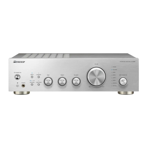
Pioneer GM-X622 X1R/UC User manual

Pioneer

Pioneer GM-X622 X1R/UC User manual

Pioneer A-09 User manual

Pioneer

Pioneer A-09 User manual

Pioneer GM-X374 User manual

Pioneer

Pioneer GM-X374 User manual

Pioneer M-IS22 User manual

Pioneer

Pioneer M-IS22 User manual
Pioneer A-88X User manual

Pioneer

Pioneer A-88X User manual

Pioneer SCU-M2096ZH User manual

Pioneer

Pioneer SCU-M2096ZH User manual

Pioneer VSA-AX10 User manual

Pioneer

Pioneer VSA-AX10 User manual

Pioneer A-303R User manual

Pioneer

Pioneer A-303R User manual

Pioneer M-IS22V User manual

Pioneer

Pioneer M-IS22V User manual

Pioneer SA-8800/S/G User manual

Pioneer

Pioneer SA-8800/S/G User manual

Pioneer A-509R User manual

Pioneer

Pioneer A-509R User manual

Pioneer SA-7100 KUW User manual

Pioneer

Pioneer SA-7100 KUW User manual

Pioneer PRS-X340 User manual

Pioneer

Pioneer PRS-X340 User manual

Pioneer PRS-D1000M User manual

Pioneer

Pioneer PRS-D1000M User manual

Pioneer KEH-P5200RDS User manual

Pioneer

Pioneer KEH-P5200RDS User manual

Pioneer GM-D8704 User manual

Pioneer

Pioneer GM-D8704 User manual

Pioneer RS-P90/EW5 User manual

Pioneer

Pioneer RS-P90/EW5 User manual

Pioneer Premier PRS-A900 User manual

Pioneer

Pioneer Premier PRS-A900 User manual

Pioneer GM-D9605 User manual

Pioneer

Pioneer GM-D9605 User manual

Pioneer DC-200Z User manual

Pioneer

Pioneer DC-200Z User manual

Pioneer GM-D505 User manual

Pioneer

Pioneer GM-D505 User manual

Pioneer GM-D8704XEVUC User manual

Pioneer

Pioneer GM-D8704XEVUC User manual

Pioneer SA-9900 User manual

Pioneer

Pioneer SA-9900 User manual

Pioneer GM-X374 User manual

Pioneer

Pioneer GM-X374 User manual

Popular Amplifier manuals by other brands

Magnat Audio EDITION FOUR Owner's manual/warranty document

Magnat Audio

Magnat Audio EDITION FOUR Owner's manual/warranty document

Inter-m PA-2000A Operation manual

Inter-m

Inter-m PA-2000A Operation manual

Yamaha TX6n owner's manual

Yamaha

Yamaha TX6n owner's manual

Peavey TNT 150 user guide

Peavey

Peavey TNT 150 user guide

Bosch LBB 1903/10 Installation and user instructions

Bosch

Bosch LBB 1903/10 Installation and user instructions

Avocent Emerge DA1200D Installer/user guide

Avocent

Avocent Emerge DA1200D Installer/user guide

Redgum RGi35 operating instructions

Redgum

Redgum RGi35 operating instructions

Cambridge Audio AXA25 user manual

Cambridge Audio

Cambridge Audio AXA25 user manual

Alpine MRP-M200 owner's manual

Alpine

Alpine MRP-M200 owner's manual

Technical Pro H1502UrBT user manual

Technical Pro

Technical Pro H1502UrBT user manual

FMS EMGZ307 operating manual

FMS

FMS EMGZ307 operating manual

Racal Instruments 5601 user manual

Racal Instruments

Racal Instruments 5601 user manual

Valcom V-1094A Technical specifications

Valcom

Valcom V-1094A Technical specifications

Cambridge Audio 851D user manual

Cambridge Audio

Cambridge Audio 851D user manual

QSC 3800 Specifications

QSC

QSC 3800 Specifications

NAD C300 owner's manual

NAD

NAD C300 owner's manual

Rotel RMB-1077 owner's manual

Rotel

Rotel RMB-1077 owner's manual

Peavey Monitor 300 Series operating guide

Peavey

Peavey Monitor 300 Series operating guide

manuals.online logo
manuals.online logoBrands
  • About & Mission
  • Contact us
  • Privacy Policy
  • Terms and Conditions

Copyright 2025 Manuals.Online. All Rights Reserved.

Operating
V
SURROUND
PROCESSOR/AMPLIFIER
VSP-200
Instructions
OD
PHONEETR
6.
gmc
mmcimcr
anewes
VR
ROO
WARNING:TO
PREVENT
FIRE
OR
SHOCK
HAZARD,DO
NOT
EXPOSE
THIS
APPLIANCE
TO
RAIN
OR
MOISTURE
Thank
you
for
buying
this
Pioneer
products
Please
read
through
these
Operating
Instructions
so
you
will
know
how
to
operate
your
model
properly.After
you
have
finished
reading
the
Instructions,
put
them
away
in
a
safe
place
for
future
reference.
in
some
countries
or
regions,the
shape
of
the
power
plug
and
power
outlet
may
sometimes
differ
from
that
shown
in
the
explanatery
drawings
However,the
method
of
connecting
end
operating
the
unit
is
|
’This
product
complies
with
the
Radio
interference
require-
ments
of
the
EC
(European
Community)
Directive
87/308/EEC.”
the
same.
IMPORTANT
|
|
\
|
|
|
|
|
[
CAUTION
RISK
OF
ELECTRIC
SHOCK
DO:
NOT
OPEN
CAUTION
TO
PREVENT
THE
RISK
OF
ELECTRIC
SHOCK,
DO
NOT
REMOVE
COVER
(OR
BACK).
NO
USER:
SERVICEABLE
PARTS
INSIDE.
REFER
SERVICING
TO
QUALIFIED
SERVICE
PERSONNEL
aeithen
am
equiial
|
rasnales
|
es
|
|
IMPORTANT
FOR USE
IN
THE
UNITED
KINGDOM
‘The
wires
in
this
mains
lead
are
coloured
in
accodance
with
the
following
code:
blue
neutral
brown
five
if
the
plug
provided
is
unsuitable
for
your
socket
outlets,
the
piug
must
b¢
cut
off
and
a
suitable
plug
fied.
The
cut-off
plug
should
be
disposed
of
and
must
nat
be
inserted
into
any
13
amp
socket
as
this
can
resuit
in
electric
shock.
The
plug
or
adaptor
or
the
distribution
panel
should
be
provided
with
5
amp
fuse.
As
the
colours
of
the
wires
in
the
mains
lead
of
this
appliance
may
not
correspond
with
coloured
markings
identifying
the
terminals
in
your
plug,
proceed
as
follows:
The
wire
which
is
coloured
blue
must
be
connected
to
the
terminal
which
is
marked
with
the
letter
N
or
coloured
black.
The
wire
which
is
coloured
brown
must
be
connected
to
the
termiaai
which
is
marked
with
the
letter
(
or
coloured
red.
Do
not
connect
either
wire
to
the
earth
terminal
of
a
three
pin
plug.
NOTE
|
After
repiacing
of
changing
a
fuse,
the
fuse
cover
in
|
the
plug
must
be
replaced
with
a
fuse
cover
which
corresponds
te
the
colour
of
the
insert
in
the
base
of
the
plug
or
the
word
that
is
embossed
on
the
base
of
the
plug,
and
the
appliance
must
not
be
used
without
4
fuse
cover.
if
lost,
replacement
fuse
covers
can
be
obtained
from
your
dealer
|
Only
5
A
fuses
approved
by
B.S.1,
oF
AS.T.A.
10
B.S,
1362
should
be
used.
@
PIONEER
3
The
Art
of
Entertainment
CONTENTS
ACCESSORY
ITEMS
...
SURROUND
EFFECT
..
DOLBY
3CH
LOGIC
DOLBY
PRO
LOGIC
SURROUND,
DOLBY
3CH
LOGIC
CENTER
MODE
...
SPEAKER
INSTALLATION
..........
CONNECTIONS
(0.601000
REAR
PANEL
FACILITIES
..
FRONT
PANEL
FACILITIES
...
REMOTE
CONTROL
UNIT
FACILITIES
DOLBY
PRO
LOGIC
SURROUND
AND
3CH
LOGIC
..
OPERATING
THE
CONNECTED
COMPONENTS
.
TROUBLE
SHOOTING
..
SPECIFICATIONS
oh he
Sat
tt
topo
bBWN
OMI
Oh
EB
EWN
ACCESSORY
ITEMS
Power
cord
Remote
control
unit
Dry
cell
batteries
(size
AA(R6P/SUM-3)}
LOCATION
Install
the
amplifier
in
a
well-ventilated
lacation
where
it
will
not
be
exposed
to
high
temperatures
or
humidity.
Do
not
install
the
amplifier
in
a
location
which
is
exposed
to
direct
rays
of
the
sun,or
near
hot
appliances
or
radiators.Excessive
heat
can
adversely
affect
the
cabinet
and
internal
components
Installation
of
the
amplifier
in
@
damp
or
dusty
environment
may
result
in
a
mulfunction
or
accidentiAlse
avoid
installation
near
cookers,etc..where
the
amplifier
may
be
exposed
to
smoke,steam,or
heat).
2
<ARB1488>
REMOTE
CONTROL
RANGE
When
operating
the
remote
control
unit,point
the
front
of
the
unit
at
the
front
panel
of
the
processor.The
remote
con-
trol
unit
may
be
used
within
a
range
of
about
7
meters
from
the
remote
sensor,within
angles
of
up
to
about
30
degrees.
Performance
of
the
remote
control
unit
is
adversely
affected
in
the
presence
of
strong
fluorescent
light.Keep
such
lights
away,especially
frorn
the
sensor
window.
on
a
<
wf
war
30°
7
x
i
Battery
Replacement
As
battery
power
runs
down,
the
range
over
which
the
re-
mote
control
unit
can
operate
decreases.When
the
range
becomes
too
short,change
the.
batteries
CONDENSATION
When
rhe
unit
is
brought
into
a
warm
room
from
previously
cold
conditions
or
when
the
room
temperature
is
suddenly
increased,condensation
may
from
inside
and
the
unit
may
not
be
able
to
attain
its
full
periormance
In
case
like
this,aliow
the
unit
to
stand
for
about
an
hour
or
raise
the
room
temperature
gradually
|
PUTTING
BATTERIES
INTO
THE
REMOTE
|
CONTROL
UNIT
1.
Open
the
battery
compartment
cover
on
the
rear
of
the
remote
contro!
unit.the
cover
should
open
easily
if
you
side
it
in
the
direction
of
the
arrow
while
pressing
on
it
with
your
thumb
2.
Take
out
the
two
supplied
batteries
size-
AA*(REP),and
insert
then
into
thebattery
compartment
in
accordance
with
the
indications
in
the
compartment.
3.
Close
the
cover
of
the
battery
compartment.
Incorrect
use
of
batteries
may
lead
to
leakage
or
rupture.Al
ways
be
sure
to
follow
these
guidelines:
A.
Always
insert
ba
tteries
into
the
battery
compartment
cor-
rectly
matching
the
positive
(+Jand
negativel-)polalities,as
indicated
inside
the
compartment
B.
Never
mix
new
and
used
batteries
Cc.
Batteries
of
the
same
size
may
have
different
voltages,
depending
on
their
type.Do
not
mix
different
types
of
batter-
ies.
SURROUND
EFFECT
This
unit
has
a
built-in
surround
processor
for
adding
presence
and
an
expansive
effect
to
the
sound
+
STUDIO:
Select
this
position
to
enjoy
the
effect
of
listening
to
music
in
@
recording
studio.
The
source
sound
is
output
as
it
is
through
the
front
speakers,with
reverberation
output
through
the
rear
speakers
This
is
particularly
suitable
for
a
source
that
has
a
lot
of
reverbelation
+
SIMULATED
SURROUND:
The
"SIMULATED
SURROUND"
creates
effects
of
rever-
berated
and
reflected
sound
from
the
walls
and
ceiling
simi-
jar
to
a
concert
hall.
These
sound-effects
added
to
the
actual
sound
from
the
source
make
you
feel
as
if
you
were
ina
more
expanded
space.The
different
anges
of
the
expanded
space
can
be
set
by
the
DELAY
TIME
button
on
the
remote
control
unit
Set
the
delay
time
tol5ms
or
20ms
for
a
live-house
concert.For
chamber
music,set
to
20ms.For
orchestral
music,set
to
30ms.
The
“SIMULATED
SURROUND‘also
gives
effects
on
monaural
sources
by
outputting
the
rever-
berated
sound
from
rear
speakers
while
keeping
the
output
sound
frorn
front
speakers
as
it
is.
Turn
on
the
“SIMULATED
SURROUND*
for
a
monaural
source
to
gain
effective
sur-
round
playback
+
DOLBY*PRO
LOGIC
SURROUND:
Choose
this
setting
for
movies
and
music(especially
Video
Dises
and
video
tapes
bearing
the
DO
[baev
sunrouns)
mark)playback.
DOLBY
PRO
LOGIC
SURROUND
continuously
detects
the
size
and
direction
of
the
dominant
signal
and
cancels
undesirable
crosstalk,
thereby
providing
signal
emphasis.
It
makes
you
clearly
perceive
the
directions
where
the
music
comes
from.real
flow
of
sound
can
also
be
re-created
naturally
using
this
feature.You
can
feel
as
if
being
in
an
outstanding
and
expansive
sound
field.
When
using
DOLBY
PRO
LOGIC
SURROUND
,a
delay
time
setting
of
20ms
is
commonly
used.Use
a
different
setting
if
you
prefer.
Even
if
they
do
not
bear
the
D[povey
sunnouno]
mark,some
video
recordings
may
be
Dolby
Surround
encoded
Choose
the
SIMULATED
SURROUND
mode
if
the
source
sound
signal
is
mono.Little
or
no
sound
will
be
heard
from
the
surround
speakers
if
the
STUDIO
or
DOLBY
PRO
LOGIC
SURROUND
mode
is
selected.
With
DOLBY
PRO
LOGIC
SURROUND,
monaural
source
sound
will
be
heard
only
from
the
center
channel
at
settings
other
than
the
PHANTOM
position.
Note:
Dalby
Surround
will
not
operate
correctly
if
the
signal
passes
through
a
graphic
equalizer
When
using
Dolby
Surround,set
the
graphic
equalizer
for
flat
response
or
to
its
"through’(or
off
)setting,if
you
have
one
in
use.
*
Manufactured
under
license
from
Dolby
Laboratories
Licensing
Corporation.
DOLBY
and
the
double-D
symbai
DO
are
trademarks
of
Dolby
Laboratories
Licensing
Corporation.
3
<ARB1488>
DOLBY
3CH
LOGIC
Cornbining
the
rear
speaker
signal
with
that
of
the
front
speakers
results
in
you
being
able
to
enjoy
2
regenarated
sound
field
which
has
comparatively
more
presence
and
a
more
expansive
feeling
from
the
front
3channels(front
L.frontR,and
center
speakers)than
that
of
ordinary
stereo
regeneration.
DOLBY
PRO
LOGIC
SURROUND,DOLBY
3CH
LOGIC
CENTER
MODE
[For
DOLBY
PRO
LOGIC
SURROUND
and
DOLBY
3CH
LOGIC}
You
can
choose
from
the
following
settings:
Center
Mode
Choices:
When
using
a
center
speaker:
*NORMAL-Low
range
frequencies,
which
have
little
effect
on
directionality
and
positioning,are
routed
to
the
left
and
right
front
speakers.So
you
can
use
a
relatively
small
size
speaker
as
the
center
speaker.
-WIDE-If
you
use
a
large
size
center
speaker,choose
this
setting.
The
full
frequency
range
of
the
Dolby
Surround
cen-
ter
channel,
from
low
to
high,is
routed
to
the
center
speaker
When
not
using
a
center
speaker
DOLBY
PRO
LOGIC
SUR-
ROUND
only
*PHANTOM-The
signal
which
would
have
been
sent
to
the
center
speaker
is
divided
equally
between
the
left
and
right
SPEAKER
INSTALLATION
Speaker
Installation
Example
for
Surround
To
get
the
most
out
of
the
surround
system,
piace
the
speak-
ers
as
shown
below.
An
example
of
speaker
location
Rear
left
speaker
Rear
right
speaker
@
—
Front
teft
speaker
@
Center
speaker
@
Front
tight
speaker
@
FRONT
@®
Listening
area
©
REAR
(0)
®
4
<ARBI488>
front
speakers.
if
the
rear
speakers
are
positioned
at
an
extreme
distance,
the
surround
ievel
will
be
unable
to
adjust
and
the
surround
effect
will
not
be
fully
achieved.
NOTE:
To
avoid
interference
with
the
picture
on
a
nearby
TV
set,use
magnetically
shielded
speaker
systems.
This
is
particularly
important
for
the
center
speaker
since
it
is
usually
located
closest
to
the
TV.
Position
the
left
and
right
channel
speakers
at
equal
distances
from
the
TV
set
and
approximately
2
meters
from
each
other.
Position
the
center
speaker
above, below,
or
behind
the
TV
set.Sound
may
not
appear
to
coincide
with
the
picture
if
you
position
it
next
to
the
TV
set.
*Rear
speakers
are
best
positioned
slightly
above
ear
level.
CONNECTIONS
|
AUDIO/VIDEO
CONNECTIONS
TV
monitor
Refer
to
page
7
for
CONTROL
IN/OUT
connection.
OR
&
{PLAY}
(REC)
OUT
IN
5
<ARB1488>
CONNECTIONS
SPEAKER
CONNECTIONS
Power
amplifier
Center/rear
speaker
cord
connection
Oo
®
@
>
Push
the
lever
uptor
down)
@®
Insert
the
cord
@®
Pull
the
lever
back.
ae
Rear
(
}
‘y
AD
re
NOTE:
40
an
«
For
the
center
and
rear
speakers,
use
speaker
systems
having
impedance
of
8Q
to
169.
*
Do
not
allow
any
of
the
cord’s
conductors
to
protrude
from
the
terminals
or
touch
any
other
conductors
Malfunctioning
or
breakdowns
may
occur
when
conduc-
tors
come
into
contact
with
each
other
6
<ARBI488>
REAR
PANEL
FACILITIES
(1)
VIDEO
input
jacks
Connect
to
visual
appliance’s
output
jacks
(audio,
video)
(2
LDinput
jacks
Connect
to
LOplayer’s
output
jacks(audio,
video)
@
TV
input
jacks
Connect
to
TV
tuner's
output
jacks(audio,
video)
@
VCR
jacks
Connect
to
a
VCR.
(3)
VIDEO
OUTITO
MONITOR
TV)jack
Connect
to
a
monitor
TV
(@)
CENTER
PRE
OUT
jack
When
using
the
center
speaker
with
another
amplifier,connect
this
to
the
amplifier’s
audio
input.And
when
using
the
TV’s
built-in
speakers
as
the
center
speaker,connect
this
to
the
TV's
audio
input
@
SUB
WOOFER
OUT
jack
lf
you
want
to
boost
the
low
frequencies,or
you
want
to
use
he
unit
ina
3D
system,connect
this
to
a
sub
woofer
power
amplifier
@)
FRONT
PRE
OUT
jacks
When
a
separate
power
arnplifier
is
used
to
drive
the
front
speakers,connect
the
power
amplifier
to
these
jacks
(
CENTER
SPEAKER
terminals
Connect
the
center
speaker
to
these
terminals
Use
center
speaker
with
impedance
of
BQto16Q
4
REAR
SPEAKERS
terminals
Connect
the
rear
speakers
to
these
terminals.
Use
rear
speakers
with
impedance
of
8Qto16Q
1}
CONTROL
IN/OUT
jacks
IN:
Connect
this
jack
to
other
Pioneer
components(main
unit
or
remote
control
unit)
when
using
those
components
to
control
this
out
OUT:
Connect
this
jack
to
other
Pioneer
components
when
using
the
remote
control
of
this
unit
to
control
other
components
NOTE:
The
VSP-200's
remote
sensor
does
not
function
when
a
plug
is
inserted
in
the
IN
jack.
To
operate,
point
the
remote
contro!
unit
at
the
remote
sensor
on
the
compornent
to
which
the
VSP-200's
IN
jack
is
connected.
VSP-200
Pioneer
compornent
bearing
the
(i
mark.
To
the
CONTROL
IN
jack
of
the
Pioneer
compornent
bear
Remote
control
unit
ing
the
fil
mark.
42
AC
INLET
Connect
power
cord
to
here
and
on
AC
outlet
of
an
audio
timer.
If
you
are
going
to
be
away
from
home
a
long
period
of
time.disconnect
the
unit
from
wail
socket.
7
<ARB1488>
FRONT
PANEL
FACILITIES
—~
@
QD
PIONEER
2
pmcnc
mons
mnnee
VECO
@
POWER
STANDBY/ON
switch/STANDBY
indicator
This
is
the
switch
for
electric
power.
ON:
When
set
to
the
ON
position,
power
is
supplied
and
the
unit
becomes
operational.
When
set
to
STANDBY
position,
the
main
power
flow
is
cut
and
the
unit
is
no
longer
fully
operational.A
minute
flow
of
power
feeds
the
unit
to
maintain
operation
readiness.
The
STANDBY
indicator
light
when
the
power
is
STANDBY,and
goes
out
during
ON.
[Timer
ON/OFF
possible]
When
the
unit
is
switched
ON,
ON/OFF
control
can
be
performed
by
means
of
the
optional
timer
NOTE:
When
the
power
is
intially
turned
ON,
muting
will
be
applied
to
prevent
sound
from
being
output
for
about
6
seconds.
STANDBY:
@
INPUT
SELECTOR
buttons
Each
time
these
buttons
are
pressed,
the
function
changes
in
the
following
sequence:
Ch
ceca
"|
VCR
VIDEO:
@
SURROUND
MODE
button
Each
time
this
button
is
pressed,the
surround
mode
changes
in
the
following
sequence:
off
—-»
DOLBY
PRO
LOGIC
STUDIO
SIMULATED
SURROUND
8
<ARBIABS>
@
MASTER
VOLUME
control
After
adjusting
the
volume
level
on
the
amplifier
you
are
using,adjust
volume
to
the
same
level
with
this
MASTER
VOLUME
control.
®
DOLBY
3CH
LOGIC
button
Use
it
to
change
DOLBY
3CH
LOGIC
to
ON/OFF
position.
©
CENTER
MODE
indicators
(NORMAL,
WIDE,PHANTOM)
Lights
up
when
a
center
mode
is
selected
with
the
CENTER
MODE
button
of
the
remote
control
unit.
@
Display
section
SURROUND
MODE
indicators
(DOLBY
PRO
LOGIC,
SIMULATED,
STUDIO)
Lights
up
when
a
surround
mode
is
selected
with
the
SUR-
ROUND
MODE
button.
FRONT
PANEL
FACILITIES
{DISPLAY
SECTION
]
® ®
@
cae’
IW
WW
WA
WZ WZ
oie"
eeae
TANT
TM
VIM
WN UN
urine
@
REAR
LEVEL
indicator
@
DELAY
TIME
indicator
It
light
the
rear
level
settings
during
adjustment
Lights
during
SIMULATED
SURROUND
or
DOLBY
PRO
@
CENTER
LEVEL
indicator
LOGIC
SURROUND(when
using
a
DELAY
TIME).
It
light
the
center
level
settings
during
adjustment
®
MUTING
indicator
®
Character/Level
display
Flashes
when
MUTING
is
set
to
ON
Displays
function,center
level,rear
level
and
delay
time
9
<ARB3488>
|
REMOTE
CONTROL
UNIT
FACILITIES
@
POWER
button
@
TV
button
@
LD
button
@
VCR
button
®
VIDEO
button
SURROUND
MODE
button
@
DELAY
TIME
button
10
<ARB1488>
®
TEST
TONE
button
©
MUTING
button
@
MASTER
VOLUME(+/-}buttons
@®
3CH
LOGIC
button
@®
REAR
LEVEL(+/-)buttons
®
CENTER
LEVEL(+/-)buttons
@
CENTER
MODE
button