manuals.online logo
Brands
  1. Home
  2. •
  3. Brands
  4. •
  5. Pioneer
  6. •
  7. CD Player
  8. •
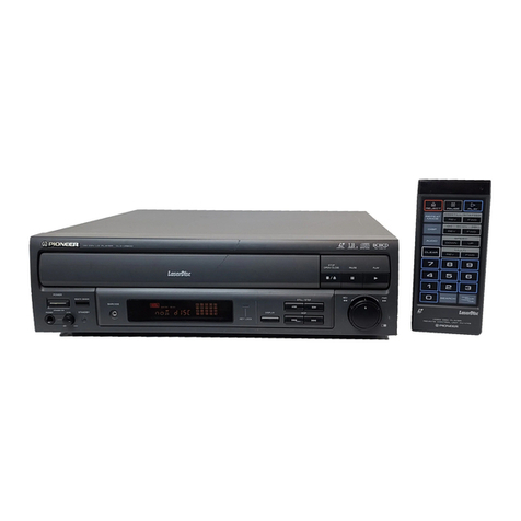
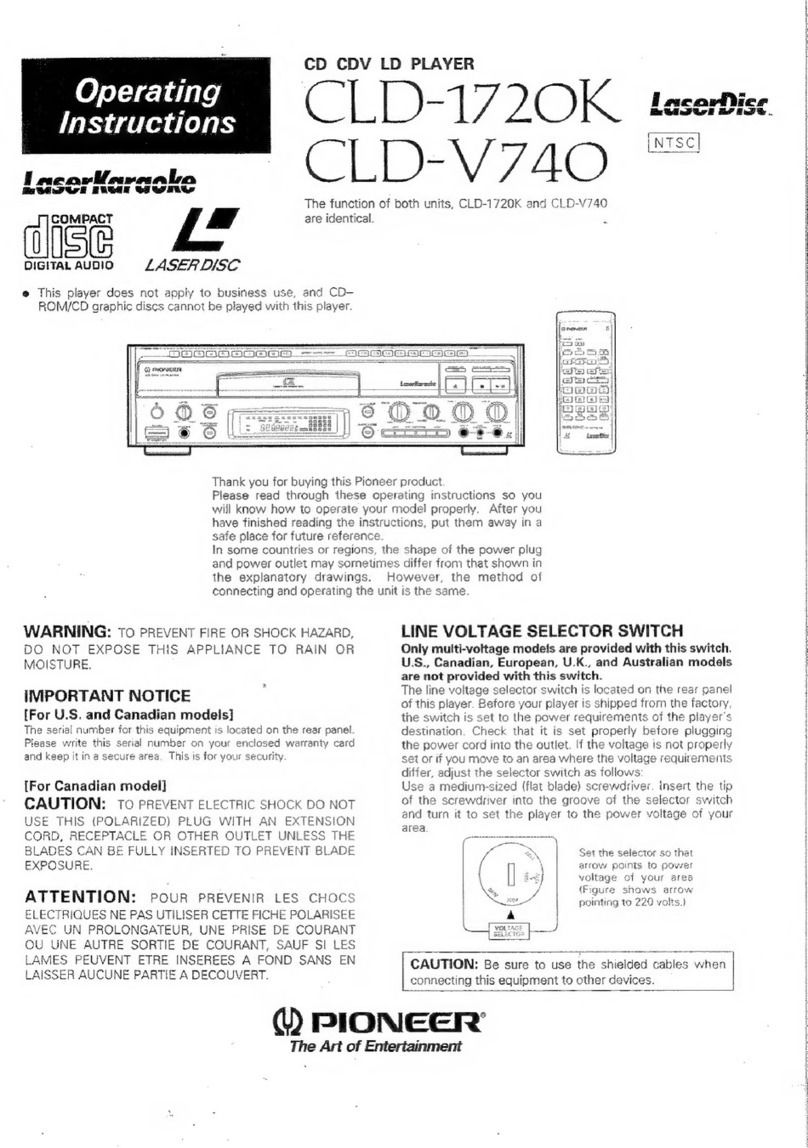
  9. Pioneer CLD-901 User manual

Pioneer CLD-901 User manual

Other manuals for CLD-901

1

Other Pioneer CD Player manuals

Pioneer CDX-M2086ZBM User manual

Pioneer

Pioneer CDX-M2086ZBM User manual

Pioneer PD-J900M User manual

Pioneer

Pioneer PD-J900M User manual

Pioneer CDJ 200 - Pro Cd/Mp3 Player User manual

Pioneer

Pioneer CDJ 200 - Pro Cd/Mp3 Player User manual

Pioneer LaserDisc CLD-D760 User manual

Pioneer

Pioneer LaserDisc CLD-D760 User manual

Pioneer Elite PD-D6MK2-KElite D6 User manual

Pioneer

Pioneer Elite PD-D6MK2-KElite D6 User manual

Pioneer CDJ 1000MK3 - Professional CD/MP3 Turntable User manual

Pioneer

Pioneer CDJ 1000MK3 - Professional CD/MP3 Turntable User manual

Pioneer Elite PD-D9-J User manual

Pioneer

Pioneer Elite PD-D9-J User manual

Pioneer CLD-97 User manual

Pioneer

Pioneer CLD-97 User manual

Pioneer SUPERTUNER III D DEH-P2650 User manual

Pioneer

Pioneer SUPERTUNER III D DEH-P2650 User manual

Pioneer CDJ-100S User manual

Pioneer

Pioneer CDJ-100S User manual

Pioneer DEH-P6300R User manual

Pioneer

Pioneer DEH-P6300R User manual

Pioneer PD-7500 User manual

Pioneer

Pioneer PD-7500 User manual

Pioneer SUPER AUDIO CD PLAYER PD-D9MK2-K User manual

Pioneer

Pioneer SUPER AUDIO CD PLAYER PD-D9MK2-K User manual

Pioneer PD-202 User manual

Pioneer

Pioneer PD-202 User manual

Pioneer PD-S801 User manual

Pioneer

Pioneer PD-S801 User manual

Pioneer DRM-7000 User manual

Pioneer

Pioneer DRM-7000 User manual

Pioneer BARCODE CLD-V2400 Service manual

Pioneer

Pioneer BARCODE CLD-V2400 Service manual

Pioneer PD-95 User manual

Pioneer

Pioneer PD-95 User manual

Pioneer CLD-D925 User manual

Pioneer

Pioneer CLD-D925 User manual

Pioneer LaserDisc CLD-D504 User manual

Pioneer

Pioneer LaserDisc CLD-D504 User manual

Pioneer PD-7300 User manual

Pioneer

Pioneer PD-7300 User manual

Pioneer X-CM56 User manual

Pioneer

Pioneer X-CM56 User manual

Pioneer DEH-1400 User manual

Pioneer

Pioneer DEH-1400 User manual

Pioneer DRM-7000 User manual

Pioneer

Pioneer DRM-7000 User manual

Popular CD Player manuals by other brands

Arcam CD23 Handbook

Arcam

Arcam CD23 Handbook

Sanyo MCD-Z1F Service manual

Sanyo

Sanyo MCD-Z1F Service manual

JVC RC-ST3SL instructions

JVC

JVC RC-ST3SL instructions

Technics SL-P9066 operating instructions

Technics

Technics SL-P9066 operating instructions

Marantz HD-CD1 quick start guide

Marantz

Marantz HD-CD1 quick start guide

Sony DVP-FX850 Service manual

Sony

Sony DVP-FX850 Service manual

Philips AZ1140 Instrukcja obs?ugi

Philips

Philips AZ1140 Instrukcja obs?ugi

Alpine 7909 owner's manual

Alpine

Alpine 7909 owner's manual

JVC CH-X350 instructions

JVC

JVC CH-X350 instructions

RCA RP-7923 instruction manual

RCA

RCA RP-7923 instruction manual

Philips Shockproof AX2102 brochure

Philips

Philips Shockproof AX2102 brochure

Philips CD582 user manual

Philips

Philips CD582 user manual

Philips AZ 6821 operating manual

Philips

Philips AZ 6821 operating manual

Lasonic MSU-2020 user manual

Lasonic

Lasonic MSU-2020 user manual

Denon DCD-1420 Service manual

Denon

Denon DCD-1420 Service manual

Panasonic SJ-MR100 operating instructions

Panasonic

Panasonic SJ-MR100 operating instructions

Onkyo DX-7210 instruction manual

Onkyo

Onkyo DX-7210 instruction manual

Cambridge Audio SONATA CD30 manual 

Cambridge Audio

Cambridge Audio SONATA CD30 manual 

manuals.online logo
manuals.online logoBrands
  • About & Mission
  • Contact us
  • Privacy Policy
  • Terms and Conditions

Copyright 2025 Manuals.Online. All Rights Reserved.

enema
CAERRTARENEREE
i
measles"
BUI
et
ews
:
COMPACT
DISC/
Operating
LASERVISION
PLAYER
Instructions
CLD=-S901
VOLTAGE
SELECTOR
SWITCH
A
4-point
(110
V/120
V/220
V/240
V)
voltage
selector
switch
is
loacted
on
the
rear
panel
of
the
player.
Check
that
it
is
set
properly
before
plugging
the
power
cord
into
an
AC
outlet.
if
the
voltage
is
not
properly
set
or
if
you
move
to
an
area
where
the
voltage
supply
differs,
adjust
the
selector
switch
as
follows:
1.
Disconnect
the
power
cord.
2.
Use
a
medium-sized
(flat
blade)
screw-driver.
In-
sert
the
tip
of
the
screwdriver
into
the
groove
of
the
selector
switch
and
turn
it
to
set
the
player
to
the
power
voltage
of
your
area.
59ST
AER
ENS
EES
GE
TEE
RE
Se
RSET
RSET
vol
|
SOUTASE
|
|
OUTAGE.
|
Point
arrow
to
power
vage
of
your
area
(Figure
shows
arrow
pointing
to
240
volts.)
Thank
you
for
buying
this
Pioneer
product.
LaserVision
Videodiscs
and
Compact
disc
beaing
Please
read
through
these
operating
instructions
so
you
will
the
symbols
below
should
be
used
with
this
player.
know
how
to
operate
your
model
properly.
After
you
have
finished
reading
the
instructions,
put
them
away
in
a
safe
place
for
future
reference.
In
some
countries
or
regions,
the
shape
of
the
power
plug
and
power
outlet
may
sometimes
differ
from
that
shown
in
the
explanatory
drawings.
However,
the
method
of
con-
necting
and
operating
the
unit
is
the
same.
(LaserVision
Disc)
y
|
This
is
the
unified
symbol
mark
of
LaserVision
Videodisc
LaserVision
_|
The
LaserVision
symbol
certifies
compatibility
with
CAUTION:
Use
of
controls
or
ad-
other
laser
optical
products
bearing
the
same
justments,
or
performance
of
procedures
symbol.
ee
:
This
player
is
to
be
used
exclusively
with
the
NTSC
other
than
those
specified
herein
may
result
color
system.
Please
use
NTSC
LaserVision
discs
in
hazardous
radiation
exposure.
only.
PAL
and
SECAM
system
LaserVision
discs
CAUTION:
THE
USE
OF
OPTICAL
INSTRU-
cannot
be
used
with
this
player.
MENTS
WITH
THIS
PRODUCT
WILL
INCREASE
EYE
(Compact
Disc)
COMPACT
HAZARD.
Se
WARNING:
to
prevent
FIRE
OR
SHOCK
HAZARD,
DIGITAL
AUDIO
DO
NOT
EXPOSE
THIS
APPLIANCE
TO
RAIN
OR
MOISTURE.
Y)
PIONEER’
"seca
8
SST
TEE
TESS
EE
USSU
EA
SEES
ESSE
BFS
ORE
SRST
SS
SESE
PA
ESTEE
ES
SS
HEE
SAFETY
INSTRUCTIONS
READ
iNSTRUCTIONS
—
All
the
safety
and
operating
instructions
should
be
read
before
the
appliance
is
operated.
RETAIN
INSTRUCTIONS
—
The
safety
and
operating
instructions
should
be
retained
for
future
reference.
HEED
WARNINGS
—
All
warnings
on
the
appliance
and
in
the
operating
instructions
should
be
adhered
to.
FOLLOW
INSTRUCTIONS
—
All
operating
and
use
instructions
should
be
followed.
CLEANING
—
Unplug
this
video
product
from
the
wall
outlet
before
cleaning.
Do
not
use
liquid
cleaners
or
aerosol
cleaners.
Use
a
damp
cloth
for
cleaning.
ATTACHMENTS
—
Do
not
use
attachments
not
recommended
by
the
video
product
manufacturer
as
they
may
cause
hazards.
WATER
AND
MOISTURE
—
Do
not
use
this
video
product
near
water
—
for
example,
near
a
bathtub,
wash
bowl,
kitchen
sink,
or
laundry
tub,
in
a
wet
basement,
or
near
a
swimming
pool,
and
the
like.
ACCESSORIES
—
Do
not
place
this
video
product
on
an
unstable
cart,
stand,
tripod,
bracket,
or
table.
The
video
product
may
fall,
causing
serious
injury
to
a
child
or
adult,
and
serious
damage
to
the
appliance.
Use
only
with
a
cart,
stand,
tripod,
bracket,
or
table
recommended
by
the
manufac-
turer,
or
sold
with
the
video
product.
Any
mount-
ing
of
the
appliance
should
follow
the
manufac-
turer's
instructions,
and
should
use
a
mounting
ac-
cessory
recommended
by
the
manufacturer.
VENTILATION
—
Slots
and
openings
in
the
cabinet
are
provided
for
ventilation
and
to
ensure
reliable
operation
of
the
video
product
and
to
protect
it
from
overheating,
and
these
openings
must
not
be
blocked
or
covered.
The
openings
should
never
be
blocked
by
piacing
the
video
product
on
a
bed,
sofa,
rug,
or
other
similar
surface.
This
video
pro-
duct
should
never
be
placed
near
or
over
a
radiator
or
heat
register.
This
video
product
should
not
be
placed
in
a
built-in
installation
such
as
a
bookcase
or
rack
unless
proper
ventilation
is
provided
or
the
manufacturer's
instructions
have
been
adhered
to.
POWER
SOURCES
—
This
video
product
should
be
operated
only
from
the
type
of
power
source
in-
dicated
on
the
marking
label.
If
you
are
not
sure
of
the
type
of
power
supply
to
your
home,
consult
your
appliance
dealer
or
local
power
company.
For
video
products
intended
to
operate
from
battery
power,
or
other
sources,
refer
to
the
operating
in-
structions.
POLARIZATION
—
This
video
product
is
equipped
wjth
a
polarized
alternating
current
line
plug
(a
plug
having
one
blade
wider
than
the
other).
This
plug
wilt
fit
into
the
power
outlet
only
one
way.
This
is
a
safety
feature.
If
you
are
unable
to
insert
the
plug
fully
into
the
outlet,
try
reversing
the
plug.
If
the
plug
should
still
fail
to
fit,
contact
you
electrician
to
replace
your
obsolete
outlet.
Do
not
defeat
the
safety
purpose
of
the
polarized
plug.
POWER-CORD
PROTECTION
Power-supply
cords
should
be
routed
so
that
they
are
not
likely
to
be
walked
on
or
pinched
by
items
placed
upon
or
against
them,
paying
particular
at-
tention
to
cords
at
plugs,
convenience
receptacles,
and
the
point
where
they
exit
from
the
appliance.
IMPORTANT
The
lightning
flash
with
arrowhead,
within
an
equilateral
triangle,
is
intended
to
alert
the
user
of
the
presence
of
uninsulated
‘‘dangerous
voltage”
within
the
product's
enclosure
that
may
be
of
sufficient
magnitude
to
constitute
a
risk
of
electric
shock
to
persons.
<VRB1001>
SERVICE.ENTRANCE
EQUIPMENT
POWER
SERVICE
GROUNDING
ELECTRODE
SYSTEM
fe-g
sntenor
metal
water
pipe!
FIG.A
LIGHTNING
— For
added
protection
for
this
video
product
receiver
during
a
lightning
storm,
or
when
it
is
left
unattended
and
unused
for
long
periods
of
time,
unplug
it
from
the
wall
outlet
and
disconnect
the
antenna
or
cable
system.
This
will
prevent
damage
to
the
video
product
due
to
lightning
and
power-line
surges.
POWER
LINES
—
An
outside
antenna
system
should
not
be
located
in
the
vicinity
of
overhead
power
lines
or
other
electric
light
or
power
circuits,
or
where
it
can
fall
into
such
power
lines
or
circuits.
When
installing
an
outside
antenna
system,
ex-
treme
care
should
be
taken
to
keep
from
touching
such
power
lines
or
circuits
as
contact
with
them
might
be
fatal.
OVERLOADING
—
Do
not
overload
wall
outlets
and
extension
cords
as
this
can
result
in
the
risk
of
fire
or
electric
shock.
OBJECT
AND
LIQUID
ENTRY
—
Never
push
objects
of
any
kind
into
this
video
product
through
openings
as
they
may
touch
dangerous
voltage
points
or
short-out
parts
that
could
result
in
a
fire
or
electric
shock.
Never
spill
liquid
of
any
kind
on
the
video
product.
SERVICING
~—
Do
not
attempt
to
service
this
video
product
yourself
as
opening
or
removing
covers
may
expose
you
to
dangerous
voltage
or
other
hazards.
Refer
all
servicing
to
qualified
service
per-
sonnel.
POWER
LINES
SEAVICE
ENTRANCE
CONDUCTORS)
+
GROUND
WIRE
a,b,
a
1
GROUND
3
CLAMPS
REQUIRED
BY
i
LOCAL
CODES
SEE
u
NEC
SECTION
810
21
11
CAUTION
RISK
OF
ELECTRIC
SHOCK
DO
NOT
OPEN
CAUTION:
TO
PREVENT
THE
RISK
OF
ELECTRIC
SHOCK.
DO
NOT
REMOVE
COVER
(OR
BACK).
NO
USER-
SERVICEABLE
PARTS
INSIDE.
REFER
SERVIC-
ING
TO
QUALIFIED
SERVICE
PERSONNEL.
STAND-OFF
.
.
INSULATORS
b
(8.4
mm?)
aluminum
wire,
TO
EXTERNAL
ANTENNA
TERMINALS
OF
PRODUCT
ANTENNA.
DISCHARGE
UNIT
c
GROUND
WIRE
3.0
OPTIONAL
ANTENNA
GROUNDING
ELECTRODE
NDING
i}
DRIVEN
8
FEET
(2
44
mi
SOMPER
cy
ie
into
THE
EARTH
IF
lj
DAMAGE
REQUIRING
SERVICE
Unpiug
this
video
product
from
the
wail
outlet
and
refer
servicing
to
qualified
service
personnel
under
the
following
conditions:
a.
When
the
power-supply
cord
or
plug
is
dam-
aged.
b.
If
liquid
has
been
spilled,
or
objects
have
fallen
into
the
video
product.
c. If
the
video
product
has
been
exposed
to
rain
or
water.
d.
If
the
video
product
does
not
operate
normally
by
following
the
operating
instructions.
Adjust
only
those
controls
that
are
covered
by
the
operating
in-
structions
as
an
improper
adjustment
of
other
con-
trols
may
result
in
damage
and
will
often
require
ex-
tensive
work
by
a
qualified
technician
to
restore
the
video
product
to
its
normal
operation.
e.
if
the
video
product
has
been
dropped
or
the
cabinet
has
been
damaged.
f.
When
the
video
product
exhibits
a
distinct
change
in
performance
—
this
indicates
a
need
for
service.
REPLACEMENT
PARTS
—
When
replacement
parts
are
required,
be
sure
the
service
technician
has
used
replacement
parts
specified
by
the
manufac-
turer
or
having
the
same
characteristics
as
the
original
part.
Unauthorized
substitutions
may
result
in
fire,
electric
shock
or
other
hazards.
SAFETY
CHECK
—
Upon
completion
of
any
service
or
repairs
to
this
video
product,
ask
the
service
technician
to
perform
safety
checks
to
determine
that
the
video
product
is
in
proper
operating
condi-
tion.
OUTDOOR
ANTENNA
GROUNDING
—
if
an
out-
side
antenna
is
connected
to
the
antenna
terminal,
be
sure
the
antenna
system
is
grounded
so
as
to
provide
some
protection
against
voltage
surges
and
build
up
static
charges.
In
the
U.S.A,
section
810
of
the
National
Electrical
Code,
ANSI/NFPA
No.
70-1984,
provides
informa-
tion
with
respect
to
proper
grounding
of
the
mast
and
supporting
structure,
grounding
of
the
lead-in
wire
to
an
antenna
discharge
unit,
size
of
ground-
ing
conductors,
location
of
antenna-discharge
unit,
connection
to
grounding
electrodes,
and
re-
quirements
for
the
grounding
electrode.
See
Fig.
A.
a)
Use
No.
10
AWG
(5.3
mm?)
copper
wire,
No.
8
AWG
No.
17
AWG
(1.0
mm?)
copper-clad
steel
wire,
bronze
wire
or
larger
wire
as
ground
wire.
ANTENNA
-i
eae
b)
Secure
antenna
lead-in
and
ground
wires
to
house
with
stand-off
insulators
spaced
from
4
feet
(1.22
meters)
to
6
feet
(1.83
meters)
apart.
c)
Mount
antenna
discharge
unit
as
closely
as
possible
to
where
lead-in
enters
house.
d)
Use
jumper
wire
not
smaller
than
No.6
AWG
(13.3
mm?)
copper
or
equivalent
when
separete
antenna-ground-
ing
electrode
is
used.
The
exclamation
point
within
an
equilateral
triangle
is
intended
to
alert
the
user
of
the
presence
of
important
operating
and
maintenance
(servicing)
instructions
in
the
literature
accompanying
the
appliance.
SRS
SASSER
AER
EPSTEIN
&
:
e
|
t
5
i
i
a
i
&
i
FO
ACUPOS
cescevesecti.icepigeeis
Ris
cess
icc
lacsedecesacdecscavedeealcevasseet
dntanes
DISCS
ices
tat
Ne
th
hee
ce
ves
SINE
Od.
Disc
Handling
Precautions
...........
cc
ceeeeeeeeseeeeeeeeeeees
Before
Operation
02...
cccecccesccsceeecescsseeseaceeseesessessseseess
Rear
Panel
Facilities
0.0.0...
cee
ceecseeecesereeeeees
CORRECTIONS
<2.
ccccccdecdiealbcks
hateavsesbve
ceceadeclucbecesedbeasessasiice
r
CONTENTS
Basic
Operation
.....2.
ce
cccccccecessssssssecssceeeeecesereeseers
Remote
Control
Operations
0.0...
ecceeeeeeeeeeeeeees
LaserVision
Disc
Playback
Functions
Compact
Disc
Playback
Functions
00.0.0...
Program
playback
oo...
.cecccececsesececssessescecssceseesneass
TrOUBDIESHOOTING
00...
ee
eceeeeseseeseseteesenecseesectecsecestacssease
Specifications
FEATURES
AUTOSTART
FUNCTION
WITH
AUTOMATIC
DISCRIMINATION
OF
COMPACT
DISC/LASER-
VISION
DISC
When
the
disc
table
with
a
disc
set
upon
it
is
drawn
into
the
player,
the
player
automatically
discriminates
the
type
of
disc
on
the
table,
and
begins
playback.
CX
NOISE
REDUCTION
SYSTEM
When
use
is
made
of
CX
encoded
LaserVision
discs,
an
expanded
dynamic
range
and
greatly
increased
signal
to
noise
ratio
are
obtained.
EXTERNAL
CONTROL
The
player
is
provided
with
an
I/O
PORT
and
control
input/output
terminals.
These
enable
it
to
be
con-
trolled
by
a
personal
computer,
or
to
be
connected
into
systems
comprising
products
with
the
PIONEER
mark.
CAN
PLAY
BACK
THE
DIGITAL
SOUND
OF
“LASERVISION
WITH
DIGITAL
SOUND
DISCS”
Can
play
back
the
digitally
recorded
sound
of
the
LaserVision
with
Digital
Sound
Discs.
There
is
no
need
for
any
extra
adaptor.
LINEAR
SERVO
SYSTEM
DURING
COMPACT
DISC
PLAYBACK
The
player
employs
a
linear
servo
system
in
which
any
scratches
or
dirt
are
detected
by
a
preceding
beam.
This
allows
jumping
of
playback
due
to
dirt
or
scratches
to
be
avoided.
WHEN
TRANSPORTING
THE
PLAYER,
Transport
the
Player
in
CD
Mode
When
moving
house
etc.,
transport
the
player
after
first
putting
it
into
Compact
Disc
playback
mode
(so
that
the
CDP
indicator
lights),
and
then
switching
off
power.
If
the
Player
is
Not
in
CD
Mode,
Insert
a
Compact
Disc,
and
when
the
CDP
indicator
lights,
eject
and
remove
the
disc.
Push
the
disc
table
back
into
the
player,
and
after
the
PLAY
indicator
stops
flashing,
switch
off
the
power.
After
the
PLAY
indicator
stops
flashing,
switch
off
the
power.
3
<VRB1001>
PERERA
RP
EO
PSI
ERE
SETS
FT
TTS
SI
ES
TSH
OA
RSET
CRRA
A
O
TT
RTSENOTS
PONIES
NOES
CHEATER
EARSTE
eT
PS
EET
Eo
PE
SETTERS
SSA
EST
SETS
ST
TE
SEI
LST
SE
TNS
CS
SSE
Fs
vs
4
a!
4
DISCS
The
CLD-901
can
play
both
LaserVision
discs
and
Compact
Discs.
Unlike
conventional
phonograph
records,
these
discs
are
played
back
from
the
inside
edge
out.
LaserVision
discs
are
available
as
both
standard
play
discs
and
extended
play
discs.
Discs
with
digitally
recorded
sound
are
also
available.
STANDARD
PLAY
(CAV)
DISC
Standard
play
discs
are
played
at
constant
angular
velocity
(CAV).
One
frame
is
recorded
for
each
revolution
of
the
disc,
and
a
12-inch
disc
can
contain
up
to
54,000
frames
on
one
side
(normal
playing
time
30
minutes).
Still-frame/step
frame,
multi-speed,
repeat,
and
other
forms
of
trick
playback
are
available
with
these
discs.
With
discs
on
which
chapter
numbers
have
been
recorded,
chapter
skip
and
chapter
program
play
etc.
are
possible.
EXTENDED
PLAY
(CLV)
DISCS
These
discs
are
recorded
at
a
constant
linear
velocity
(CLV).
When
the
signal
is
recorded
in
this
way,
the
number
of
frames
that
are
recorded
per
revolution
of
the
disc,
increases
as
the
recording
advances
towards
the
outer
edge,
so
in
comparison
with
standard
play
discs
longer
play
is
possible.
(For
normal
playback
of
12-inch
discs,
a
maximum
playback
time
is
1
hour
is
possible.)
Extended
play
discs
cannot
be
used
for
trick
playback,
but
search
(random
access)
and
repeat
playback
may
be
performed.
With
discs
on
which
chapter
numbers
have
been
recorded,
chapter
skip
and
chapter
program
play
are
also
possible.
:
*
The
playback
time
varies
according
to
the
disc.
4
<VRB1001
>
LASERVISION
WITH
DIGITAL
SOUND
DISCS
dicital
SOUND
The
jackets
and
labels
of
these
discs
bear
the
symbol
on
the
left.
in
addition
to
the
conventional
analog
sound
signals,
LaserVision
with
Digital
Sound
Discs
also
have
re-
corded
on
them
the
same
kind
of
pulse-code-
modulated
sound
signals
that
are
recorded
on
Compact
Discs.
The
high
quality
pictures
of
these
LaserVision
Discs,
can
be
enjoyed
together
with
digital
sound,
at
the
same
time.
The
two
types
of
sound,
digital
and
analog,
are
recorded
onto
the
discs
using
different
frequency
bands,
as
shown
in
the
figure.
For
the
sake
of
convenience,
this
book
calls
these
sound
signals
‘‘digital
sound’’
and
‘‘analog
sound”
Digital
sound
Analog
sound
Video
signals
Qa
ise)
Recording
level
2
4
6 8
10 12
Frequency
14
MHz
Recording
signal
spectrum
CAUTION
WHEN
USING
THE
DISC
All
rights
reserved.
Unauthorized
public
performance,
broadcasting
or
copying
is
a
violation
of
applicable
laws.
ca
RSE
SE
ANS
ENE
ST
SEH
EN
RIED
EE
EN
FIST
A
ETC
se
ASR
RTOS
TT
PASI
ET
sacar
iE
NETSTAT
ASF
EOS
PZB
TPS
OT
RET
SEE
STROSS
TV
ST
SST
SISTER
EE
TESTES
TOTES
DISC
HANDLING
PRECAUTIONS
aw
DO
NOT
USE
DAMAGED
DISCS
Discs
rotate
inside
the
player
at
high
speeds.
Do
not
use
damaged
(warped,
cracked,
etc.)
discs.
The
player
may
be
damaged
as
a
result.
m
This
player
may
be
used
with
LaserVision
Discs
and
Compact
Discs
bearing
the
following
symbols:
(LaserVision
Disc)
1
This
is
the
standard
LaserVision
symbol.
y
|
The
LaserVision
symbol
certifies
=
DO
NOT
AFFIX
GUMMED
SEALS
TO
THE
compatibility
with
other
laser
DISC
optical
products
bearing
the
same
symbol:
Do
not
affix
paper
or
gummed
seals
to
the
signal
surface
or
label
of
a
disc.
Also
be
careful
not
to
scratch
the
label
surface
of
a
Compact
Disc.
Laservisk
(Compact
Disc)
ee
DIGITAL
AUDIO
This
player
has
been
designed
for
use
exclusively
with
the
NTSC
television
system,
and
it
cannot
be
used
with
television
sets
of
other
systems
(such
as
PAL,
or
SECAM).
F
In
addition,
LaserVision
Discs
bearing
the
PAL
or
SECAM
marks
cannot
be
used
with
this
player.
Use
only
LaserVision
Discs
conforming
to
the
NTSC
system.
m=
BEFORE
PLAYING,
CLEAN
YOUR
DISCS
When
fingerprints
or
other
dirt
are
on
the
disc
surface,
this
may
cause
a
skipping,
jumping,
or
sticking
problem.
Always
be
sure
to
clean
your
discs
before
playing
them.
Use
a
soft
cloth
with
diluted neutral
detergent
to
remove
heavy
dirt
or
fingerprints.
When
cleaning,
wipe
away
dust
and
dirt
from
the
inner
edge
outward.
Do
not
wipe
around
the
disc.
an
m
AS
MUCH
AS
POSSIBLE,
TRY
NOT
TO
TOUCH
THE
SURFACE
OF
THE
DISC
When
holding
discs,
handle
them
as
shown
in
the
illustration,
and
try
as
much
as
possible
not
to
touch
their
playing
surfaces.
If
the
surfaces
of
the
discs
are
scratched,
it
may
C22
YX
Lightly
wipe
from
the
inner
edge
outward.
Do
not
wipe
around
the
disc.
cause
track
skipping
if
the
scratches
are
severe.
How
to
hold
the
LaserVision
Disc
Holding
with
both
hands...
Hold
the
disc
by
its
edges
with
both
hands,
as
shown
in
Fig.
A.
Holding
with
one
hand...
As
shown
in
Fig.
B,
hold
the
disc
by
its
center
hole
and
one
edge.
Do
not
use
record
cleaning
sprays,
or
static
pre-
vention
sprays
etc.
Also,
do
not
use
other
types
of
cleaners,
etc.,
containing
benzene,
thinner
or
other
solvents.
m@
KEEP
YOUR
PLAYER
AWAY
FROM
HEAT
Do
not
place
the
player
on
top
of
the
amplifier
or
any
other
unit
that
emits
heat
since
heat
may
adversely
affect
the
player
and
possible
warp
a
loaded
disc.
If
the
player
is
used
with
other
audio
equipment
in
the
same
rack,
place
it
on
the
lowest
shelf
away
from
heat,
and
keep
the
area
well
ventilated.
Fig.
A
Fig.
B
How
to
hold
the
Compact
Disc
Hold
the
disc
by
its
edges
as
shown
in
Fig.
C
TAKE
GOOD
CARE
OF
YOUR
VALUABLE
DISCS
SO
THAT
YOU
CAN
ALWAYS
ENJOY
BEAUTIFUL
PICTURE
AND
SOUND.
Fig.
C
5
<VRB1001>
ARERR
SRR
aS
AEE
AINE
ERR
AS
PERERA
AGAR
Se
SRSA
TERA
SSE
ROIS
ARRAS
RENEE
RTE
hee
SESE
Te
ERE
PR
PP
ET
ET
PSO
HC
SEBO
ESE
SE
SESS
PST
SSS
SES
GES
SSS
SE
SEE
ESE
HEN
BEFORE
OPERATION
INSTALLING
THE
PLAYER
@
Choose
a
stable
platform
next
to
the
television
and
stereo
system
with
which
you
plan
to
use
the
player.
@
When
using
the
player
with
a
stereo
system,
your
speakers
should
be
installed
somewhat
separated
from
your
television
(or
TV
monitor).
@
Do
not
place
your
television
(or
TV
monitor)
on
top
of
the
player.
Also
do
not
place
the
player
on
top
of
your
television
(or
TV
monitor).
PROVIDE
SUFFICIENT
VENTILATION
Do
not
place
the
player
on
long
pile
carpet
or
on
a
bed
or
sofa
etc.,
as
this
may
result
in
ventilation
holes
becoming
blocked.
This
would
impair
heat
dissi-
pation
and
could
result
in
breakdown.
Also,
do
not
place
the
player
above
an
amplifier
or
other
heat
generating
device.
When
putting
the
player
in
a
rack
together
with
other
audio
equipment,
the
player
should
be
placed
on
a
lower
shelf
than
the
amplifier
(as
low
as
possible
so
long
as
there
is
no
dust
build
up
problem),
and
should
be
used
after
ensuring
good
ventilation.
PUTTING
BATTERIES
INTO
THE
REMOTE
CONTROL
UNIT
1.
Open
the
battery
compartment
cover
on
the
rear
of
the
remote
control
unit.
The
cover
should
open
easily
if
you
press
on
it
with
your
thumb
while
sliding
it
in
the
direction
of
the
arrow.
.
Take
out
the
two
accessory
size
“AAA”
(IEC
RO3)
dry
batteries,
and
insert
them
into
the
battery
compartment
in
accordance
with
the
indications
in
the
compartment.
.
Close
the
cover
of
the
battery
case.
Incorrect
use
of
batteries
may
lead
to
leakage
or
rupture.
Always
be
sure
to
follow
these
guidelines:
A.
Always
insert
batteries
into
the
battery
compartment
correctly
matching
the
positive
(+)
and
negative
(-)
polarities,
as
shown
by
the
display
inside
the
compartment.
.
Never
mix
new
and
used
batteries.
.
Batteries
of
the
same
size
may
have
differing
voltages,
depending
on
brand.
Do
not
mix
different
brands
of
batteries.
.
Both
rechargeable
and
non-rechargeable
batteries
are
available.
Be
sure
to
use
your
batteries
in
accordance
with
the
caution
labels
affixed
to
them.
6
<VRB1001>
MOISTURE
CONDENSATION
If
the
player
is
brought
from
cool
surroundings
into
a
warm
room,
or
if
the
temperature
of
the
room
rises
suddenly,
condensation
may
form
in
the
operating
system
and
objective
lens
of
the
player.
While
condensation
is
present,
it
will
not
be
possible
for
signals
to
be
read
out
by
the
laser
beam.
Depending
on
the
degree
of
condensation,
let
the
player
stand
for
an
hour
or
two
in
its
new
sur-
roundings
with
the
power
switched
on.
When
the
player
reaches
room
temperature,
the
condensa-
tion
will
evaporate,
and
playback
will
be
possible.
The
same
symptoms
of
condensation
may
be
caused
during
summer,
if
the
player
is
exposed
to
the
breeze
from
an
air
conditioner.
In
such
cases
change
the
location
of
the
player.
NOTE
If
the
player
is
switched
on
during
reception
of
FM
or
AM
broadcasts,
the
player
may
interfere
with
reception.
When
the
player
is
not
being
used,
please
switch
it
off.
Also,
if
the
player
causes
interference
when
a
broadcast
is
being
received
with
an
indoor
antenna,
please
adjust
the
direc-
tion
of
the
antenna.
1
ESOC
SENSOR
SUNT
:
£
i
i
:
seg
DSO
HE
HET
SSUES
EIEN
SLL
TS
IEG
SOR
SEI
seth
RETA
AAI
THERA
ee
ANG
TERIA
eS
<A
RF
ER
ESE
HSE
EES
ERED
I
ENO
ESET
RET
TES
ESSA
ENE
“See
ENERO
ARTRTOST
REAR
PANEL
FACILITIES
VHF
OUT
terminal
(75
©
F-type
jack)
Connect
this
terminal
to
your
TV
set’s
VHF
antenna
terminal.
VHF
CHANNEL
SELECTOR
(CH3/CH4)
This
switch
is
for
switching
the
internal
VHF
converter.
Set
to
the
channel
which
is
not
used
for
TV
broad-
casts
in
your
area.
SUBCODE
OUT
terminal
(round
miniature
connector)
This
is
an
output
terminal
for
subcodes
recorded
on
Compact
disc.
(Provided
for
future
applications.)
ANTENNA
terminal
(75
(
F-type
jack)
Connect
the
coaxial
cable
(75
Q)
from
the
VHF
TV
antenna
to
this
terminal.
A
1/O
PORT
(U-shape
8-pin
DIN
connector)
This
is
the
input/output
port
used
when
performing
external
control
of
the
player.
CONTROL
IN
and
OUT
terminals
(miniature
phone
jack)
These
terminals
are
for
communication
of
control
codes,
when
the
player
is
used
together
with
other
Pioneer
products
with
the
Pioneer
mark.
VIDEO
OUT
terminal
(RCA
jack)
Connect
this
jack
to
a
TV
monitor
or
a
TV
set
which
is
provided
with
a
video
input
terminal.
LV
(ANALOG)
AUDIO
OUT
terminals
(RCA
jacks)
These
terminals
output
the
analog
audio
only
of
LaserVision
Discs.
Connect
them
to
the
AUX
input
terminals
etc.
of
your
stereo
amplifier.
Do
not
connect
these
terminals
to
your
amplifier
PHONO
input.
These
terminals
do
not
output
the
digital
sound
from
Compact
Discs
or
LaserVision
with
Digital
Sound
Discs.
CD/LV
AUDIO
OUT
terminals
(RCA
jacks)
These
terminals
output
Compact
Disc
audio,
Laser-
Vision
Disc
audio
(analog)
and
the
audio
for
Laser-
Vision
with
Digital
Sound
Discs.
Selection
of
either
digital
or
analog
sound
can
be
made
by
operating
a
button
on
the
front
panel.
Connect
these
terminals
to
the
CD
or
AUX
input
terminals
etc.
of
your
stereo
amplifier.
Do
not
connect
them
to
your
amplifier
PHONO
input.
(exis
(Sica
For the
VOLTAGE
-//9|©
©
;
sooa
tie
refer
to
o
~~
i
page
1.
Power
cord
Connect
this
to
a
power
outlet.
ABOUT
THE
AUDIO
OUTPUT
TERMINALS
This
player
is
equipped
with
two
sets
of
audio
output
terminals.
As
shown
in
the
table
below,
the
CD/LV
terminals
are
able
to
output
all
the
audio
signals
that
can
be
played
back
by
the
player.
Type
of
Disc
|
favback
Output
Terminals
Compact
Disc
_
|
Digital
CD/LV
with
Digeal
Digital
|cD/LV<—
Can
be
selected
Sound
Discs
aS
the
LVP
AUDIO
i
i
button
on
the
ae
2
Analog
|cp/Lv<—
front
panel.
the
defaf
mark)
LV(Analog)
LaserVision
Discs
(Discs
without
the
difal
mark)
CD/LV
LV(ANALOG)
Analog
For
ordinary
operation,
connect
the
CD/LV
ter-
minals
to
your
amplifier.
The
LV
(ANALOG)
terminals
are
provided
for
developmental
use.
They
do
not
need
to
be
used
for
ordinary
operation.
For
details
regarding
selection
of
either
digital
sound
or
analog
sound
when
playing
back
LaserVision
with
Digital
Sound
Discs,
please
refer
to
page
19
“AUDIO
REPRODUCTION”.
NOTE:
The
sound
output
from
the
VHF
output
terminal
is
analog
sound.
When
a
TV
set
is
connected
to
the
VHF
output
terminal,
it
cannot
be
used
to
listen
to
Compact
Disc
sound,
or
to
the
digitally
recorded
sound
on
LaserVision
with
Digital
Sound
Discs.
7
<VRB1001>
SAR
TESA
BEB
EBA
SESS
ERT
ESTES
ASR
RRO
MEN
RR
aoa
<7
ET
IEEE
BS
SRE
EST
FEI
TE
ESTP
EI
TET
EE
FINO
ET
CONNECTIONS
BASIC
COMBINATION
When
making
connections,
switch
off
power
to
the
CLD-901
+
TV
set
+
Stereo
system
+
(VCR)
player
and
other
units
to
be
connected,
and
remove
the
plugs
of
each
unit
from
the
power
outlets.
Switch
on
power
after
connections
have
been
made.
VHF
antenna
a
UHF
antenna
*
During
disc
playback,
switch
off
power
Speaker
system
to
the
VCR.
62
ESTE
ASE
EC
EE
US
SE
STN
SE
NT
TE
TT
TSE
SR
RRS
Accessory
antenna
amplifier
CLD-901
RN
SSS
ONE
ESSA
connecting
cord
RF
antenna
cable
To
obtain
a
good
picture
quality,
1.
VHF
TV
ANTENNA
CONNECTION
keep
RF
antenna
cable
away
Detach
the
VHF
antenna
cable
from
the
VHF
antenna
from
power
cord.
terminal
on
your
TV
set,
and
connect
the
cable
to
the
ANTENNA
terminal
on
the
player.
If
the
end
of
the
cable
does
not
match
the
ANTENNA
terminal,
attach
the
accessory
antenna
adaptor.
I
1
1 1
1
1
sO
SES
RES
Mounting
the
antenna
adaptor
<With
a
752
coaxial
cable>
<With
a
300
Q
parallel
feeder>
@
Prepare
the
end
@
Remove
the
@®
Loosen
the
clamp
screw
and
rotate
of
the
cable.
cover.
180°
degrees.
(Remove
the
lead
wire
held
by
the
J
'
/
ime
Open
the
tabs
in
a
the
direction
of
Remove
Loosen
the
Rotate
the
clamp
(A)
and
pull
in
this
wire.
180°
degrees.
@
Attach
the
cable
to
@
Prepare
the
end
of
the
feeder.
the
direction
of
(B).
the
300
2
terminal.
@
Attach
the
©
Replace
the
coaxial
cable.
Sandwich
the
center
part
here.
Loosen
the
screw,
clamp
the
feeder
omen
up
the
cable
and
tighten
up
the
screw.
screw
after
having
secured
the
cable.
Clamp
with
pliers.
8
<VRB1001>
2s
UR
ESERIES
EES
THE
CET
ENP
TER
HIE
EEE
TE
SEN
SEF
EET
A
SRT
NSIS
2.
CONNECTING
TO
YOUR
TV
SET
Connect
the
VHF
OUT
terminal
of
the
player
to
the
75
Q
VHF
antenna
terminal
of
your
TV
set
with
the
accessory
RF
antenna
cable.
If
the
VHF
antenna
terminal
of
your
TV
set
is
not
an
F
type
terminal,
modify
one
end
of
the
cable.
TV
CLD-901
VHF
ANT
IN
752
UNBAL
Unit:
mm
75
Q
coaxial
cable
preparation
1.
Strip
the
end
of
the
cable
as
shown
in
step
1.
2.
Prepare
the
end
as
shown
in
steps
2
and
3.
3.
Loosen
the
three
screws
and
insert
the
cable.
4.
Tighten
the
three
screws
firmly.
NOTE:
@
Push
the
plug
in
firmly.
If
the
plug
is
not
properly
pushed
in,
this
may
result
in
snow
on
the
screen
or
noise.
@
The
shape
of
the
VHF
antenna
input
terminal
and
the
method
of
connecting
the
antenna
cable
may
differ
from
one
TV
set
to
another.
For
details
please
refer
to
your
TV
instruction
manual.
@
The
sound
output
from
the
VHF
OUT
terminal
is
Laser-
Vision
Disc
analog
sound.
This
terminal
does
not
allow
the
playback
of
digital
sound
or
Compact
Disc
sound.
If
the
VHF
antenna
input
terminal
of
your
TV
set
is
an
IEC
terminal,
install
the
accessory
F-type
jack-IEC
plug
adaptor
to
one
end
of
the
RF
antenna
cable
and
connect
it
to
the
TV
set.
RF
antenna
F-type
jack-IEC
cable
plug
adaptor
‘i
To
TV
set
CONNECTIONS
3.
SET
THE
CHANNEL
SELECTOR
SWITCH
If
channel
3
is
not
being
used
for
broadcasts
in
your
area,
set
the
channel
selector
switch
to
the
channel
3
side,
or
if
channel
4
is
not
being
used,
set
the
switch
to
the
channel
4
side.
The
setting
you
choose
will
be
the
disc
playback
channel.
4.
CONNECTING
TO
YOUR
STEREO
AMPLIFIER
Connect
the
CD/LV
audio
output
terminals
of
the
player
to
the
AUX
or
CD
input
terminals
etc.
of
your
stereo
amplifier.
NOTE:
@
Do
not
connect
these
terminals
to
your
amplifier
PHONO
input
terminals.
@
The
LV
(ANALOG})
audio
output
terminals
do
not
output
the
digital
sound
from
Compact
Discs
or
LaserVision
with
Digital
Sound
Discs.
5.
PLUG
THE
POWER
CORDS
INTO
AC
OUTLET
Plug
the
AC
power
cords
of
the
player,
stereo
amplifier
and
TV
set
into
an
AC
outlet.
Please
check
that
the
VOLTAGE
SELECTOR
is
set
properly.
WHEN
USING
A
TV
MONITOR
(OR
A
TV
SET
WITH
VIDEO
AND
AUDIO
INPUT
TERMINALS)
Connect
the
VIDEO
OUT
terminal
of
the
player
to
the
video
input
terminal
of
the
TV
monitor
(or
TV
set).
Connect
the
CD/LV
audio
output
terminals
of
the
player
to
the
AUX
or
CD
terminals
etc.,
of
your
stere
amplifier.
3
<VRB1001>
SERS
ESTER
EER
SB
TN
ET
CA
A
ATE
SRE
TSCA
SSRIS
STE
SR
ETS
CONNECTIONS
WHEN
COMBINED
WITH
OPTIONAL
PIONEER
COMPONENT
DISPLAY,
Connect
the
VIDEO
OUT
terminal
of
the
player
to
the
video
input
terminal
of
the
component
display,
and
connect
the
CD/LV
audio
output
terminals
of
the
player
to
the
audio
input
terminals
of
the
component
display.
(System
Control)
By
connecting
the
control
input
ter-
minal
or
the
I/O
port
of
the
player
to
the
remote
terminal
of
the
component
display,
the
system
can
be
controlled
by
aiming
the
remote
control
unit
of
the
player
at
the
remote
control
re-
ceiver
of
the
component
display.
@
To
use
the
CONTROL
input
termi-
nal,
make
use
of
a
miniature
phone
plug
cord.
@To
use
the
I/O
PORT,
prepare
a
8-pin
U-shaped
DIN
plug
<>
mini-plug
cord.
Please
refer
to
the
Auto
start
function
on
page
16.
Please
also
refer
to
the
operating
instructions
for
the
component
dis-
play.
NOTE:
When
system
control
connections
have
been
made,
the
player
can
not
be
directly
controlled
by
the
remote
control
unit.
To
operate
the
player,
aim
the
remote
control
unit
at
the
component
display.
Component
Display
WHEN
CARRYING
OUT
SYSTEM
CONTROL
WHEN
THE
PLAYER
IS
COMBINED
WITH
A
PRODUCT
WITH
THE
PIONEER
&l
MARK,
When
the
player
is
combined
with
an
AV
master
amplifier
(optional),
which
can
provide
centralized
control
of
Pioneer
products
with
the
mark,
system
control
can
be
carried
out.
Connect
the
VIDEO
OUT
terminal
of
the
player
to
the
video
disc
video
input
terminal
of
the
stereo
amplifier,
and
connect
the
CD/LV
audio
output
terminals
of
the
player
to
the
audio
input
terminals
of
the
amplifier.
Connect
the
control
output
terminal
of
the
amplifier
to
the
CONTROL
input
terminal
of
the
player,
using
a
miniature
phone
plug
<—>
miniature
phone
plug
connecting
cord.
For
details
concerning
method
of
connection
and
operation,
please
refer
to
the
operating
instructions
for
your
amplifier.
NOTE:
When
a
connecting
cord
has
been
connected
to
the
CONTROL
input
terminal,
direct
control
of
the
player
with
the
remote
control
unit
is
not
possible.
Operate
the
player
with
the
remote
control
unit
by
aiming
it
at
the
AV
master
amplifier.
10
<VRB1001>
CONTROL
OUTPUT
TOM
oe
5
NN
CD/LV
AUDIO
VIDEO
_
=~
\Q
OUTPUT
ce
RES
TSEC
EE
SSS
SP
IE
RB
RUE
TOOT
ees
se
RO
FISTS
CESSES
BENS
ER
SISTER
TES
ESS
PER
ESS
ET
ESAS
EEE
ETB
ELI
pone
<n
ec
EEE
PRE
PRS
PS
ESE
SY
ET
IS
SE
TEI
SETA