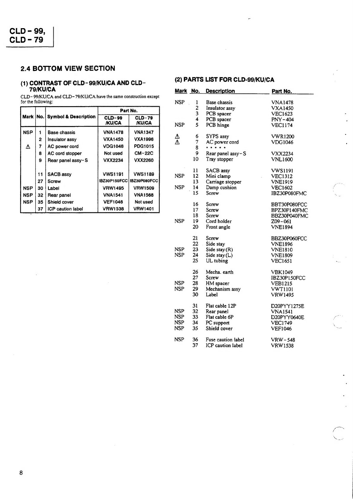
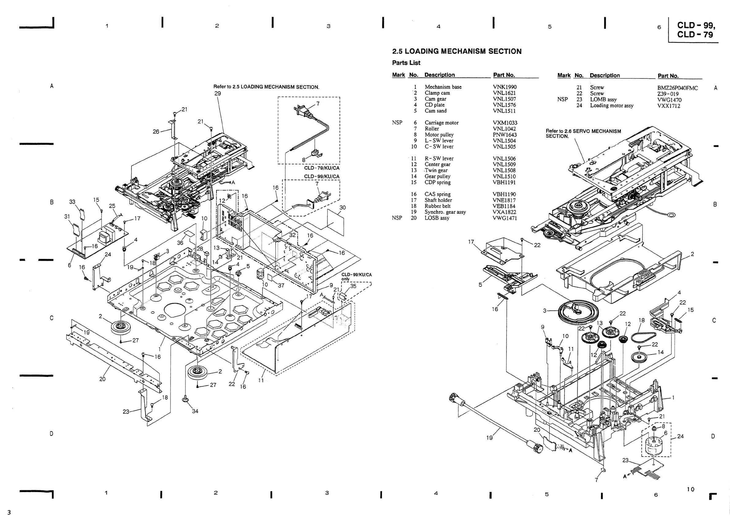
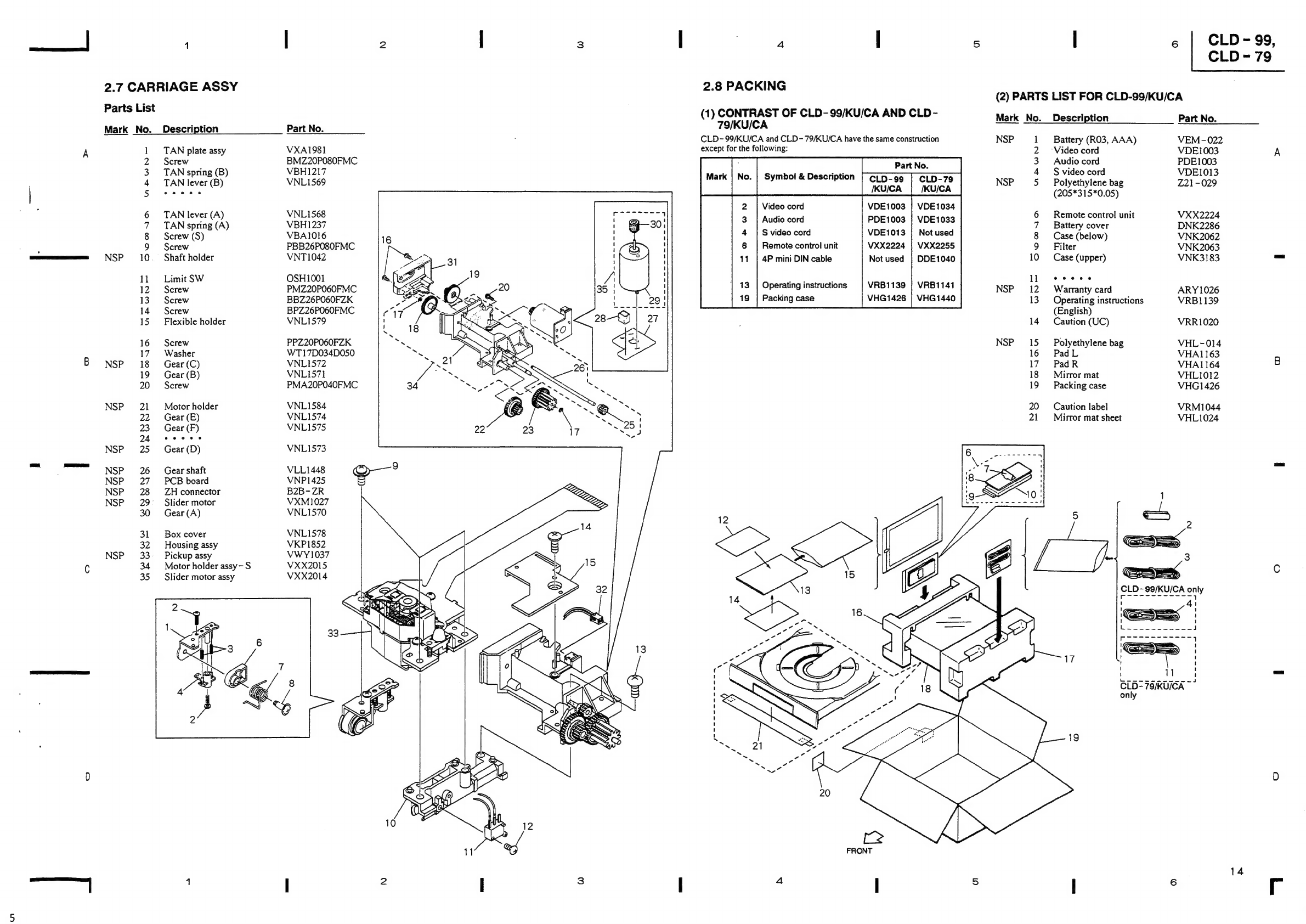
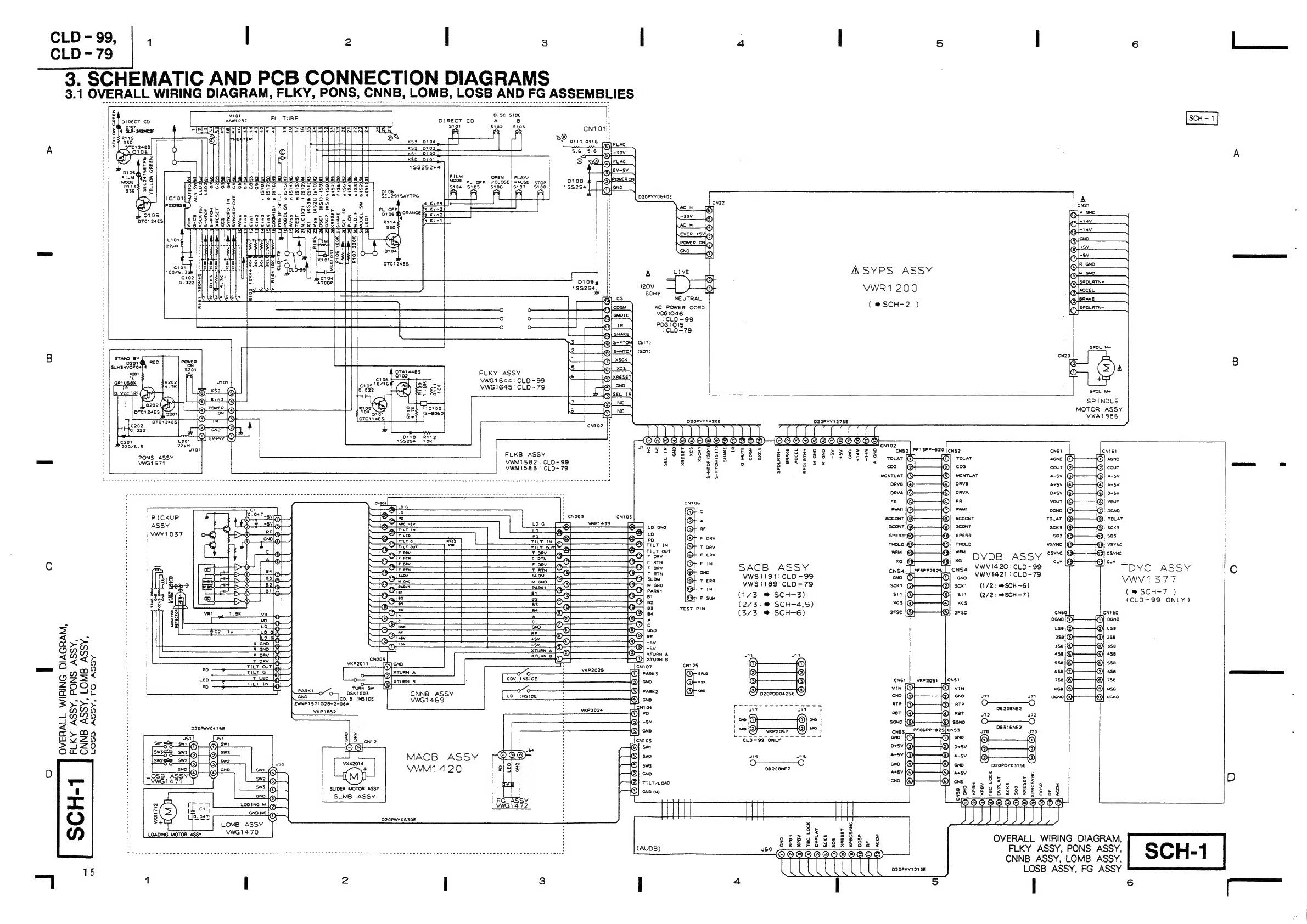
Pioneer CLD-99 User manual
Other Pioneer CD Player manuals

Pioneer
Pioneer PD-7050 User manual

Pioneer
Pioneer LaserDisc CLD-1580K User manual

Pioneer
Pioneer CDX-FM1277 User manual

Pioneer
Pioneer CDJ-200 User manual

Pioneer
Pioneer CLD-79 User manual

Pioneer
Pioneer DEH-X8750BT User manual

Pioneer
Pioneer Super Tuner IIID DEH-P5800MP User manual

Pioneer
Pioneer CDJ 1000MK3 - Professional CD/MP3 Turntable User manual

Pioneer
Pioneer CLD-A1CC User manual

Pioneer
Pioneer DRM-1004 User manual

Pioneer
Pioneer PD-F958 User manual

Pioneer
Pioneer CDJ-1000 User manual

Pioneer
Pioneer PD-M503 User manual

Pioneer
Pioneer X-HM36D User manual

Pioneer
Pioneer CDJ-100S User manual

Pioneer
Pioneer CDJ-1000MK2 User manual

Pioneer
Pioneer CMX-3000 User manual

Pioneer
Pioneer CDJ-400 - Cd/Media Player Parts list manual

Pioneer
Pioneer PD-95 User manual

Pioneer
Pioneer Elite PD-D9-J User manual