Mode Switching –Non-Pioneer Computer Users
Single Leg and Dual Leg ANT+ Modes
Switching Left and Right Sensors FROM Dual Leg to Single
Leg Mode
•Notes
•This method is for users who wish to separate a dual leg system and use single
leg crank arms . Ie. 2 different bikes.
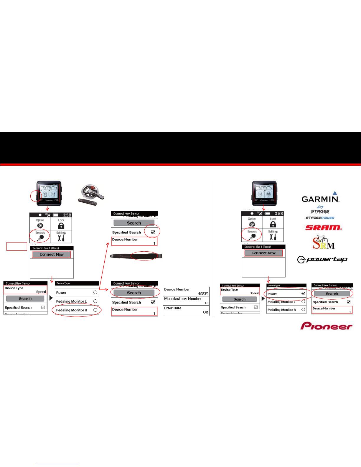
•The following method is for ANT+ Cycle Computer users who do NOT have a
Pioneer Cycle Computer –See slide 5 for Mode Switching with a Pioneer
Computer
•Dual Leg Ultegra SGY68-Series, DuraAce SGY90-Series completed cranksets
and SGY-PM9100C “Kits” ship pre-set in the Dual ANT+ Mode.
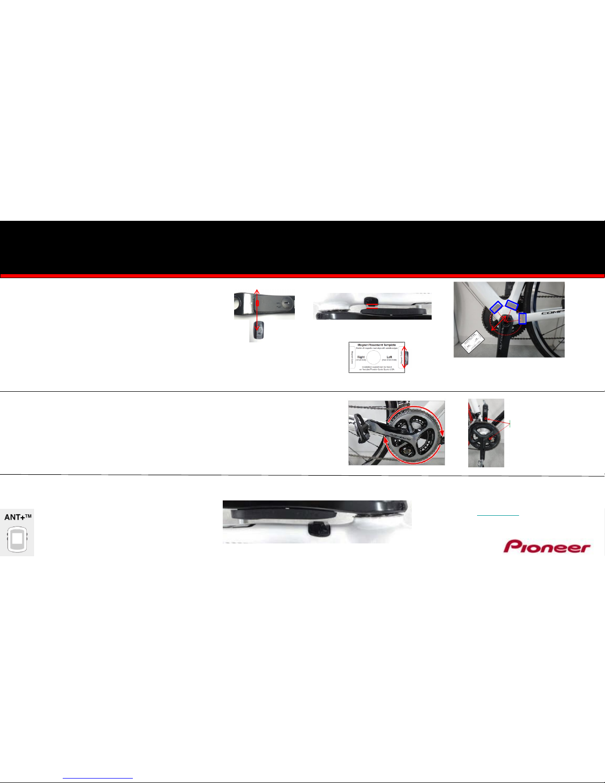
•To confirm Dual Leg ANT+ Mode, remove and replace the batteries, you should
see a SOLID Orange light on both the Left and Right Sensors.
Switching Left and Right Sensors FROM Single Leg to Dual
Leg Mode
•Notes
•This method is for users who are upgrading from a single leg sensor with a
second Left or Right leg sensor.
•The following method is for ANT+ Cycle Computer users who do NOT have a
Pioneer Cycle Computer –See slide 5 for Pioneer Mode Switching with a
Pioneer Computer
•Single Leg Ultegra SGYLT68-Series, DuraAce SGY-LT90-Series, and SGY-
PMRTC “Kits” ship pre-set in the Single Leg ANT+ Mode.
•To confirm Single Leg ANT+ Mode, remove and replace the battery, you
should see a BLINKING Orange light.
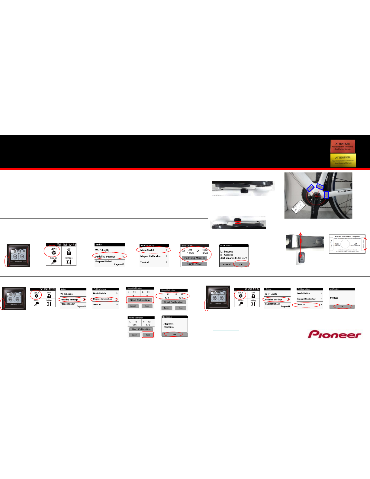
Switchingto Single Leg Mode
1. Spin the crank 3 –4 rotations to activate the Power Meter
2. Press the push switchfor 3 seconds and release
3. Bothsensors should blink orange for 10 seconds Switching to Dual Leg ANT+ Mode
1. Spin the crank 3 –4 rotations to activate the Sensors
2. Press the Push Switch for 3 seconds and release
3. Confirm both sensors are blinking
4. Whileblinking, press and hold the push switchfor 3 more
seconds and release
5. To confirm you have switched to Dual Leg, remove the
batteries and replace, you should see a solid orange light
on both sensors