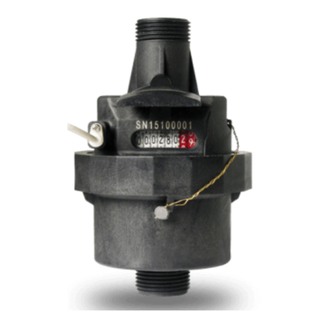
Assured Automation WM-NLD Series Instruction manual

assuredautomation.com
1-800-899-0553
Scan for more product information
Doc. AA-WMNLD-IOM-2017.06.19
WM-NLD Series
Positive Displacement Water Meters
Installation, Operation, & Maintenance Manual

WM-NLD Series Positive Displacement Water Meters - Installation, Operation, & Maintenance
1. General Information:
WM-NLD lead-free water meters use the
internationally accepted nutating disc,
positive diaplacement principle. A gear
train drives the register totalizer dials and
register. This meter comes standard with
pulse output (see pulse output details).
2. Specifications:
Materials:
Body & flanges: Lead free brass
Internals: Engineered thermoplastic
Magnet: Alnico
Maximum Pressure: 150 PSIG
Maximum Temperature: 120˚F
Accuracy: 1.5%
Sensor: dry contact reed switch
Pulse Output Rate: 1 pulse per gallon
Maximum Current: 10mA
Maximum Voltage: 24VAC/DC
Cable Length: 2 . (max. run up to 5000 .)
3. Installation:
1. Thoroughly flush the service line
upstream of the meter to remove
dirt and debris. We recommend install-
ing a strainer upstream of the meter if
water quality is poor.
2. The meter can be installed in horizontal,
vertical or inclined position. Make sure
that the direction of flow follows the
arrow cast on the meter body.
3. Slowly open any upstream valves to
prevent damage to the meter.
4. Calibration:
New meters are factory tested to meet the
AWWA C-700 meter accuracy specification.
5. Accuracy Curves:
6. Head Loss Curves:
7. Pulse Output:
The pulse output is a simple dry contact
reed switch. To use the pulse output, the
2 wires from the cable must be hooked up
to the proper terminals of your PLC, HMI,
or simple pulse counter. Polarity does not
matter for these wires. If you are using the
Assured Automation KAL-DO6 pulse counter,
the terminals to use are #2 and #6.
8. Approvals and Certifications:
• Meets NSF 61 Annex G standards
• Conforms to AWWA-C700
0
0 5 10 15 20 25 30 35 40 45 50 55
0 5 10 15 20 25 30 35 40 45 50 55
-1
-2
-3
-4
2
0
4
6
8
10
12
14
16
2
00 20 40 60 80 100 120 140 160
4
6
8
10
12
14
16
+1
+2
+3
+4
0
0 20 40 60 80 100 120 140 160
-1
-2
-3
-4
+1
+2
+3
+4
1”
1”
2”
1 1/2”
3/4”
3/4”
5/8”x1/2”
5/8”x3/4”
5/8”x1/2”
5/8”x3/4”
5/8”x1/2”
5/8”x3/4”
5/8”x1/2”
5/8”x3/4”
Flow Rate (US Gallons per minute)
Head Loss (psi)
Error (%)
Error (%)
Head Loss (psi)
0
0 5 10 15 20 25 30 35 40 45 50 55
0 5 10 15 20 25 30 35 40 45 50 55
-1
-2
-3
-4
2
0
4
6
8
10
12
14
16
2
00 20 40 60 80 100 120 140 160
4
6
8
10
12
14
16
+1
+2
+3
+4
0
0 20 40 60 80 100 120 140 160
-1
-2
-3
-4
+1
+2
+3
+4
1”
1”
2”
1 1/2”
3/4”
3/4”
5/8”x1/2”
5/8”x3/4”
5/8”x1/2”
5/8”x3/4”
5/8”x1/2”
5/8”x3/4”
5/8”x1/2”
5/8”x3/4”
Flow Rate (US Gallons per minute)
Head Loss
(psi)
Error (%)Error (%)
Head Loss (psi)
0
0 5 10 15 20 25 30 35 40 45 50 55 0 5 10 15 20 25 30 35 40 45 50 55
-1
-2
-3
-4
2
0
4
6
8
10
12
14
16
2
00 20 40 60 80 100 120 140 160
4
6
8
10
12
14
16
+1
+2
+3
+4
0
0 20 40 60 80 100 120 140 160
-1
-2
-3
-4
+1
+2
+3
+4
1”
1”
2”
1 1/2”
3/4”
3/4”
5/8”x1/2”
5/8”x3/4”
5/8”x1/2”
5/8”x3/4”
5/8”x1/2”
5/8”x3/4”
5/8”x1/2”
5/8”x3/4”
Flow Rate (US Gallons per minute)
Head Loss (psi)
Error (%)
Error (%)
Head Loss (psi)
0
0 5 10 15 20 25 30 35 40 45 50 55 0 5 10 15 20 25 30 35 40 45 50 55
-1
-2
-3
-4
2
0
4
6
8
10
12
14
16
2
00 20 40 60 80 100 120 140 160
4
6
8
10
12
14
16
+1
+2
+3
+4
0
0 20 40 60 80 100 120 140 160
-1
-2
-3
-4
+1
+2
+3
+4
1”
1”
2”
1 1/2”
3/4”
3/4”
5/8”x1/2”
5/8”x3/4”
5/8”x1/2”
5/8”x3/4”
5/8”x1/2”
5/8”x3/4”
5/8”x1/2”
5/8”x3/4”
Flow Rate (US Gallons per minute)
Head Loss (psi)
Error (%)Error (%)
Head Loss
(psi)

assuredautomation.com
Doc. AA-WMNLD-IOM-2017.06.19
9. Flow Ranges:
10. Reading the Meter:
Sizes 1/2” to 1”
1. First read the numbers from the dials on
the register. They end with the 10’s digit. If
that is accurate enough, simply add the 0
for the 1’s digit represented by permanently
painted 0 next to the register and you are done.
2. For greater accuracy, take the number
from the large needle and numbers around
the face. If the needle is in-between two
numbers, use the lower number. Use this
in place of the painted 0. This will give you
the amount to the nearest gallon.
3. For even greater accuracy, take the
number from the smaller needle, again
taking the lower number when in-between
two. Add this (with the decimal point) to
the other numbers. This will give you the
amount to the nearest 10th of a gallon.
4. For the greatest accuracy, count the
markings between the lower number
(chosen in step 3) and the needle. This will
be the 100ths digit.
Sizes 1 1/2” to 2”
1. First read the numbers from the dials on
the register. They end with the 100’s digit.
If that is accurate enough, simply add the
two 0s for the 10’s and 1’s digits represented
by permanently painted 0’s next to the register
and you are done.
2. For greater accuracy, take the number
from the large needle and numbers around
the face. If the needle is in-between two
numbers, use the lower number. Use this
in place of the painted 0’s. This will give
you the amount to the nearest 10 gallons.
3. For even greater accuracy, take the number
from the smaller needle, again taking the
lower number when in-between two. Add
this to the other numbers. This will give
you the amount to the nearest gallon.
4. For the greatest accuracy, count the
markings between the lower number
(chosen in step 3) and the needle. This will
be the 10ths digit.
Model Size High Flow Cont. Flow Low Flow Normal Flow
WM-NLD-050-R/1P 1/2” 20 15 1/8 1-20
WM-NLD-075-R/1P 3/4” 20 15 1/8 1-20
WM-NLD-7575-R/1P 3/4” 30 15 1/4 2-30
WM-NLD-100-R/1P 1” 50 25 1/4 3-50
WM-NLD-150-R/1P 1 1/2” 100 50 1 1/2 5-100
WM-NLD-200-R/1P 2” 160 80 2 8-160
1
2
3
4
5
6
7
8
9
10,23 6 24
U.S. GALLONS
001 0 2 3
0
0.1
.2
.3
.4
.5
.6
.7
.8
.9
2. The Large Dial
3. The Small Dial
(with decimal point)
4. Small Dial markings
1. The Register
10
20
30
40
50
60
70
80
90
10,23 6 2 4
U.S. GALLONS
001023
0 0
01
2
3
4
5
6
7
8
9
2. The Large Dial
(without zero if proceeding to step 3)
3. The Small Dial
4. Small Dial markings
(with decimal point)
1. The Register

WM-NLD Series Positive Displacement Water Meters - Installation, Operation, & Maintenance
12. Warranty:
WM-NLD water meters are warranted to perform to AWWA new meter accuracy standards,
and for twelve months from the shipment date will be free from defects in materials and
workmanship. If a meter fails to perform as warranted, Assured Automation will repair it
free of charge subject to the terms of this warranty. Assured Automation’s liability under
this performance warranty is expressly limited to the repair or replacement of the meter
upon the customer’s returning the complete meter prepaid to:
Assured Automation
263 Cox Street
Roselle, NJ 07203
This performance guarantee is not applicable to meters which have been damaged by
aggressive water conditions, foreign matter in media, misapplication, willful misconduct,
negligence, vandalism, act of God, improper installation, frost/freeze damage or using the
meter outside of its specific operating parameters (especially temperature and flow ranges).
In no event shall Assured Automation be liable for incidental or consequencial damages
of any kind, including but not limited to loss of profits or revenue, loss of use, cost of capi-
tal, cost of substitute equipment, facilities or services, downtime costs, delays and claims
of customers of the customer or other third parties.
11. Parts & Accessories:
Flange Kits: (for 1 1/2” & 2” meters)
Two flanges (NPT threaded for connection to
pipe) and two gaskets
WMNLD-F-150 = Flange kit for 1 1/2” meters
WMNLD-F-200 = Flange kit for 2” meters
Check Valves:
Lead free brass check valves are available to
prevent reverse flow through meter. Reverse
flow will deduct from the meter’s total. The
use of a check valve will also prevent the me-
ter and upstream water from being contami-
nated by debris or additives like fertilizer that
get added downstream from the meter.
Garden Hose Adapters: (set)
One NPT Female x Male Garden Hose Thread
One NPT Female x Female Garden Hose Thread
WMGHA050 = Adapter set for 1/2” meters
WMGHA075 = Adapter set for 3/4” meters
Digital Display with Reset:
Add a remote digital display that can be reset
to simplify reading. Simply attach the 2 wires
from the meters pulse output to terminals #2
and #6 on the display.
KAL-D06 = digital display only (for panel mount)
KAL-D06-DIN32-ENC = display in weatherproof
enclosure
C112CVLFN = 1/2”
D112CVLFN = 3/4”
E112CVLFN = 1”
G112CVLFN = 1 1/2”
H112CVLFN = 2”
This manual suits for next models
6
Other Assured Automation Measuring Instrument manuals
Popular Measuring Instrument manuals by other brands

SMART
SMART Centellis 2000 DC 1.2 quick start guide

White Instruments
White Instruments 200 manual

Keysight
Keysight EPM Series installation guide

Keysight Technologies
Keysight Technologies N774 C Series user guide

HERON
HERON dipper-T Operating & maintenance instructions

Laser Technology
Laser Technology UltraLyte LR B user manual