Carel boss micro BMBST00DP0 Installation instructions

Hardware Guide
Total Connectivity for High Efficiency Control Solutions

Models and Connections
Model Description
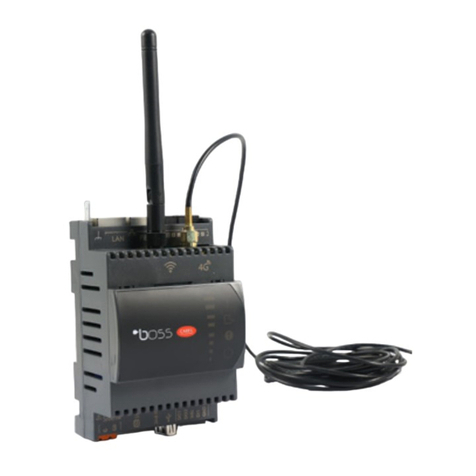
BMBST00DP0 boss micro 15 device with WIFI and 4G
BMBST00FP0 boss micro 15 device with WIFI
Accessories
BMEPS00AU Power supply 24VDC 1.5A
BMESTRLA00 Boss family 3x relay expansion module
BMBSTEWA00 WIFI antenna 3m extension
BMBSTEGA00 4G antenna 3m extension
2

Connections
BMESTRLA00 - Boss mini 3x relay expansion
Optional relay expansion for external alarm notification from boss micro.
Can be programmed for other uses where relay activation is required.
Connection is made by screw terminals using standard low voltage wiring.
Attention: wiring is depending on type of power supply to boss micro!
3
24Vac Power supply: relay module,
supplied by boss micro Vdc output. 24Vdc Power supply: relay module,
directly supplied by boss micro 24Vdc
power supply terminal G.
Note: only relay 1 + 2 of the relay module can be used with boss micro.

•Built in WIFI: Access to local mobile devices. Site personnel and service technicians
connect to the boss’ own Wi-Fi connection and can scan the QR code to access the boss’
pages. Connectivity to wireless Modbus Gateway. Further details on page 20
•Build in 4G modem: Available only on models displayed. GSM connectivity for push
notification. SIM card not included.
•Trends: View detailed graphs of temperatures & status’. Can be printed remotely or
saved as pdf. Even observe conditions in Live mode.
•Monitoring: Frequency settable from 5s to 1h, log depth settable from 1 week to 2
years (dependent on log frequency).
•Alarm management: Have up to the minute notifications through different channels
such as email, SMS, relay and the Telegram app available from Google Play and App
Store.
•Reports: Receive regular reports by email or generate them directly from boss.
•Maps: Create interactive site maps in c.web for easy viewing and navigation.
•Remote connection: Connect remotely over the web to check the status of the plant,
modify parameters and acknowledge alarms. It can save a trip to the site if not entirely
necessary.
•Commissioning report: an inbuilt function to save the original commissioning
parameters of the controllers installed on site.
•Parameters broadcast: Copy parameters from one device to others of the same type
of controller.
•Plant calendar: scheduled actions such as defrost, setpoint changes, on/off and light
control.
•Add on extra features: SW- modules to enhance and customize the boss for your
plant’s requirements. Installed credits allow for Add-ons such as Bacnet Primary MSTP
and TCP/IP, Energy Management, Floating Suction, Parameter control and Safe Restore.
Main Features
4
5
First Access Procedure
Connecting over LAN port:
•Apply power to the boss micro unit
•Follow the steps to activate the 2nd IP address on page 8
•Connect your PC via LAN ethernet connection
•Open browser and insert https://172.16.0.33
•Follow the onscreen prompts
Open an internet browser on your PC /Laptop
Apply the address https://172.16.0.33 in the address bar:
Depending on which browser you are using as to what message appears.
For Chrome users: Firefox:
Following this, the login page will appear as in the example:
Connection over build-in WIFI:
•Power up boss micro
•Search for WIFI connection uboss-xxxx (“xxxx” signifies the last 4 digits of the LAN
MAC address. Visible behind front cover
•Enter default WIFI password: 12345678
•Once connected , open a browser and insert https://uboss-xxxx or
https://qraccess/boss
•Follow the onscreen prompts
•For more details see page 9
Device info label

6
Default IP Connection
Default IP connection setup for boss micro
This is useful when resetting the network settings
You will need:
•boss micro and power supply
•Windows PC or laptop
•Ethernet cable
To setup a direct connection on boss micro LAN port, you need to first setup your PC
network to match the path of the default IP address of 172.16.0.33 .
To do this, go to:
Settings >> Ethernet >>
Change adapter options >>
Select the ethernet device and select
“Change settings of this connection”
Choose Internet Protocol Version 4
(TCP/IPv4) and go to properties.
Use the following IP address
IP address 172.16.0.32
Subnet mask 255.255.0.0
Default Gateway 172.16.0.1
To activate the default IP address, after powering up the unit, wait for approx. 30-40
seconds. Press and hold the 2nd IP button for about 3 seconds. Once released the radio
module LED will blink green if successful.
Once activated, the default address is active for 1 hour.
Default IP
Setup
button
Radio module
LED

7
Connection via WIFI
boss’s local WIFI connection is suited for easy connection with local mobile or tablet
devices.
Note: This connection is not for connecting the boss to the internet.
To connect, scan using your device’s WIF for your unique boss device and connect directly.
By default the SSID is “boss-” followed by a 4 digit/character combination.
eg. uboss-xxxx*
Note: the *suffix is always the last 4 digits of the MAC address of the boss.
Password for the WIFI connection is: 12345678
Accessing from a PC might require to follow the advanced SSID settings to enter the WIFI
key instead of a PIN.
Once connected, either scan the QR code on the front of the boss:
or: open a browser and type https://qraccess/boss
Alternatively put https://uboss-****
in the address bar and enter.
(where **** represents the last
4 digits of the mac address)
Example: https://uboss-4756
Login as normal in the boss program with the username and password that was provided
to you.

The following information is intended for the IT professional in order to achieve
connectivity of the boss unit to the local network.
Internet network connection is via standard CAT5/6 ethernet cable.
(The WIFI on the boss family is for local WIFI networking only)
The Field ethernet port is for Bacnet/ Modbus communications.
Network settings are accessed via the “System Administration” pages on the local
machine.
Login using the administrator username and password of 12345678.
IP address settings are found via the Network config (1) link and the settings icon (2) for
the LAN connection.
8
(1)
(2)
Connecting boss micro to the Internet

By default the LAN address setup is selected for DHCP, so if the network is already
connected, a static IP may already be assigned to the local network. eg.192.168.0.100
(we will use this IP address as the example in the following descriptions ).
To check local access to the boss once connected it can be accessed by using the
following link in an internet browser window.
For example: https://192.168.0.100/boss
If you want to be able access the boss unit remotely over the internet then a static
IP address from the Internet Service Provider (ISP) is required and port forwarding rules
applied to the router to achieve this.
The boss needs the following ports for functionality :
Port 443 (access for the boss main page via browser)
Port 8443 (optional for shell access)
These ports are fixed and cannot be changed.
Once the port forwarding rules have been carried out in the router you should be able to
access the boss remotely by replacing the internal IP of the link above, with the external
IP in the address bar
example: if the router external static IP address is 200.100.50.25 then the link will
become: https://200.100.50.25/boss
For added security the PING feature is deactivated by default in the “Security services”
Section. Please ensure the Firewall is reactivated to security integrity
Please note:
The above information is given as general information to help IT professionals achieve
the clients request for connectivity to LAN.
Carel Australia is unable to provide further guidance on how to set up the TCP/IP
network, this is the job of the IT personnel.
9

10
4G connectivity
Initial connection setup for boss micro
Part Number: BMBST00DP0, boss micro 4G with WIFI
Accessory: BMBSTEGA00, 3m External 4G Antenna
General Note:
−SIM card is not provided, standard size data SIM required
−Before installation review local 3G/4G reception
−If mounted inside an enclosure use external 4G antenna for signal extension
−External antenna need to be protected against rain, sunlight
−To avoid interference to with the WIFI antenna it’s recommended to use external 4G
antenna. If both external antenna’s are mounted, they must be mounted at least 30cm
apart from each other
Attention: Do not invert the WIFI antenna with the 4G antenna!
The boss micro with the above part number is a compact DIN module that’s capable of
direct push notification over 3G or 4G mobile network. With that option it’s possible to send
alarm notifications or temperature reports without any additional connection. The push
notifications can include Email, SMS and telegram messages.
Please ensure the boss micro is powered off and disconnected from power supply when
inserting the SIM card.
Inserting the SIM card:
The SIM card connector will be behind the front cover. Please remove the front cover as
illustrated below. Open the SIM card connector by using a small screwdriver and unlock
the lid of the SIM connector by gently sliding it downwards.
The standard size SIM card slides into the lid of the SIM connector.
Close the lid with the insert SIM card and lock the connector by gently pushing it upwards
into the locked position.
Close the front cover and reconnect the boss micro to the power supply.
SIM connector

11
4G connectivity
Boss micro setup:
Use the WIFI access or the LAN port with temporary IP access to connect to the boss micro
and access the System administration
After the successful login navigate to the Network configuration in the main menu. If the
main menu doesn’t appear please open it up with a click on the “burger” icon in the upper left
corner.
Under Network config, you will find the actual status of the three available connection
interfaces. Where the 4G interface only shows if the connection status is:
•Up or Down, if service is connected or disconnected
•Network IP, provided by the service operator
For more settings navigate to the tab “Modem” in the Network config.

12
4G connectivity
In the Modem settings it’s possible to setup advanced SIM settings, please check with SIM
provider/ service account setup:
•User/ Password –depending on security requirements
•APN –Access Point Name, depending on the SIM provider and data plan
•PIN –SIM card PIN, 4 digits identification number
Please leave settings blank if your standard data SIM doesn’t require any specific setup.
Confirm the data entry with a click on the connect button and to activate the GSM network
connection.
After the GSM connection was successful you can proceed to the boss application to setup
any email/ SMS or telegram notification following the steps under “IO configuration” and
“Alarm and event management”
Remote access:
The primary function of the build-in 4G modem is for push notifications. The remote access
can be enabled by using a particular SIM/ Data plan to enable a fixed and public IP address.
That option must be added by your service provider to the SIM/ Data plan.
As the build-in 4G modem doesn’t support a Dynamic DNS service it does require a direct
public IP address to browse the boss micro remotely. Additionally the IP address has to be
static, as dynamic IP addresses are getting frequently renewed and will result in a loss of
remote access.
Alternatively the boss micro is fully compatible with our RED –Reliable Enhanced Data
platform and allows also remote access. Thanks to the embedded VPN solution there is no
need for a fixed and public IP address.
In case you’re using a fixed and public IP address, remote access is possible by looking up
the provided IP address in the 4G interface status and using the following URL in your
browser: https://xxx.xxx.xxx.xxx*/boss *provided Network IP address

Troubleshooting
13
LED indicator:
A 4G modem Status
•Green: 4G modem active
•Green flashing: temporary IP on LAN port enabled
B I/O Status
•Green: Digital Input closed
•OFF: Digital Input open
C Alarm Status
•Red flashing: Alarm active
•Yellow: Device not initialized (start-up not finalised)
D System ON
E Signal and Relay Status
•Green LED: GSM signal strength
•1st LED yellow flashing: Relay 1 activated
•2nd LED yellow flashing: Relay 2 activated

Notes
14

CAREL Australia Pty.Ltd
ACN. 067 528 269
Head Office - Sydney
PH. (02) 8762 9200 FAX (02) 9764 6933
Melbourne Office
PH. (03) 9550 0898 FAX (03) 9550 0878
Brisbane Office
PH. (07) 3340 5107 FAX (07) 3341 4390
boss micro HW Guide rev1.0 25/08/2021
Technical Support
Ph: (02) 8762 9200
Email: [email protected]
Sales
Ph: (02) 8762 9200
Email: [email protected]
www.carel.com
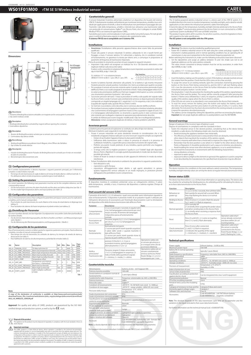
This manual suits for next models
1
Table of contents
Other Carel Measuring Instrument manuals

Carel
Carel iaq+ User manual

Carel
Carel PlantVisor Embedded Manual

Carel
Carel emeter1 User manual

Carel
Carel HYPA 3 Series User manual

Carel
Carel PGD1000F 0 Series User manual

Carel
Carel uboss Manual

Carel
Carel uC2 User manual

Carel
Carel mboss User manual

Carel
Carel NTC*HP* Series User manual

Carel
Carel iaq+ User manual
Popular Measuring Instrument manuals by other brands

OHAUS
OHAUS ST300-B instruction manual

Paragon
Paragon GUARDIAN Operation & maintenance manual

ABB
ABB Advance Optima magnos206 Operator's manual

Myron L
Myron L bluDock Ultrameter III installation instructions

Stafer
Stafer 595.K.F2.00 User and maintenance manual

PCE Health and Fitness
PCE Health and Fitness PCE-HVAC 4 user manual