Pioneer ELITE PRO-620HD Technical manual

Operating Instructions
HDTV PROJECTION MONITOR
PRO-720HD
PRO-620HD
PRO-520HD

2
Progressive Scan/HDTV READY
AllSDTVandHDTVsignalsareconvertedto1080isignalsand
displayed at high resolution.
Dual System Component Input for NTSC/
Progressive
ConnectiontoaDVDplayerwithacomponentoutputterminal
makes possible high picture-quality display, superior to that
ofS-VIDEOterminalconnection.Alsohandleshighresolution
component input (1080i, 480p), which will function as an
interface for high-quality images in future.
DUAL TUNER (SPLIT screen and SEARCH
screen function)
Two TV tuners are provided, making it possible to split the
screen vertically in two and display moving images
simultaneously on them. In addition, the channel search
functionmakesitpossibletocheck,etc.,ontheprograminthe
back. This adds remarkable convenience when you are
concerned with two programs.
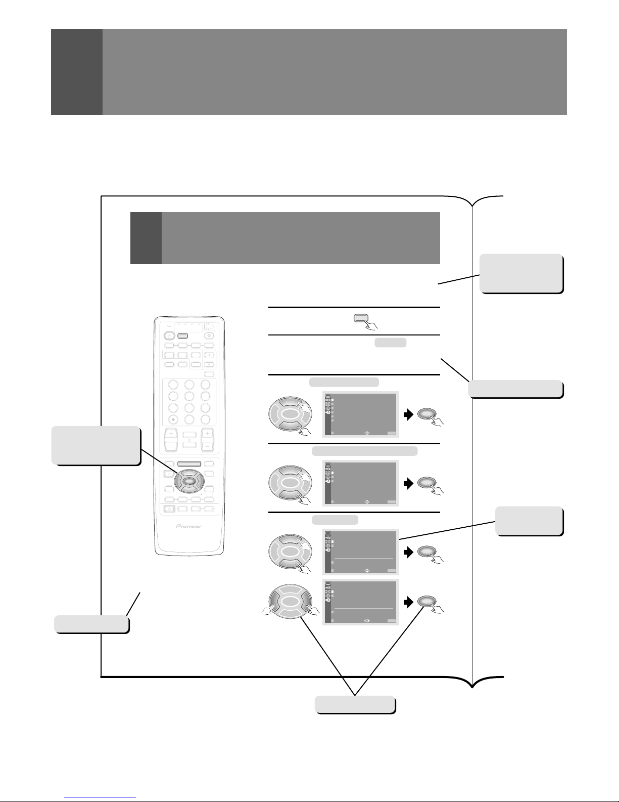
Fully Illuminated Remote Control Unit
Afullyilluminateduniversalremotecontrolisusedthatmakes
it possible to operate other devices. Remote operations can
thus be performed easily even in dark rooms and similar
environments.
Highly Detailed Image Display Technology
The 0.52mm ultrafine-pitch screen, Hi Band Video Amplifier
circuit,Progressivecontourcorrectioncircuitandvariousother
technologiesforcreatinghighpicturequalitymakethedisplay
of highly detailed images possible.
Lens System for HDTV
Adoption of a lens system for high-resolution HDTV that
faithfully reproduces HDTV 1080i signals allows highly color-
saturated images to be displayed at high resolution.
Whole Screen IR Receiver
The remote control sensor is installed behind the screen,
allowing you to operate this monitor with the remote control
unit in those installations where only the screen is revealed.
3D Y/C Separation Circuit
This three-dimensional Y/C separation circuit reproduces
clearer picture quality.
Scan Velocity Modulation Circuit
Precise images from progressive scanning can be displayed
in even greater detail, owing to the Scan Velocity Modulation
(SVM) circuit. In accordance with image type and preference,
the level of effect can be changed in terms of three stages.
Tinted Protective Screen
The accompanying protective screen is tinted, not only to
protect the screen but to present more natural high-contrast
images by renewing the color.
Pioneer's PureCinema Format Converter
An advanced and exclusive I/P (Interlace/Progressive) format
converterdevelopedbyPioneer,called“PureCinema”,delivers
a high-resolution progressive picture. It reproduces film
material in a very smooth and film-like image. This is perfect
technology for movie lovers.
Reference Theater Mode
Thismodereproducesfilm materialjust likea realfilmimage.
By cutting video enhancement circuits, the picture becomes
more natural and looks filmlike.
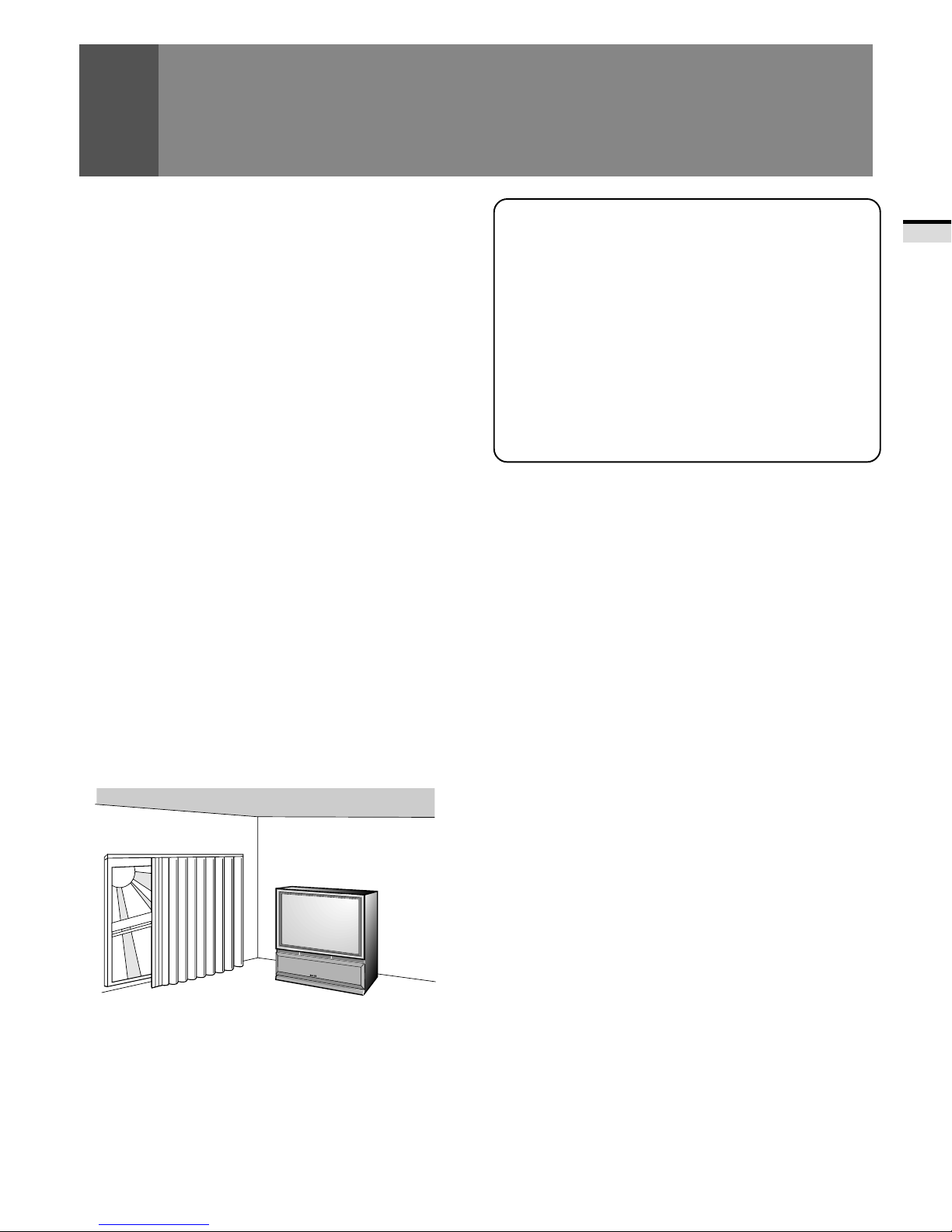
Room Light Sensor (RLS)
When you select RLS on (LEVEL 1, LEVEL 2), in accordance
withtheambient light of your room, TV automatically adjusts
the picture brightness to reduce eye strain.
Multi-Point Convergence System
Thanks to new convergence system digital technology, not
onlycanthecenterofthescreenbeadjusted,socananamazing
72otherpoints(fullmode)acrosstheviewingarea.Thismakes
it possible to display clear images with no color distortion
around the entire screen.
The adjustment is easily done using the remote control.
Program Block (V. CHIP)
You can block selected programs based on the established
rating system for television and movies.
<U.S.A. RATING SYSTEM>
The TV Parental Guidelines are used to rate television
programming: <TV-Y>, <TV-Y7>, <TV-G>, <TV-PG>, <TV-14>
and <TV-MA>.
TheMotionPictureAssociationofAmerica(MPAA)guidelines
are used to rate movies: <G>, <PG>, <PG-13>, <R>, <NC-17>,
<X> and <NR>.
<CANADIAN RATING SYSTEM>
TheCanadianEnglishLanguageRatingsystemisusedtorote
television programming: <C>, <C8+>, <G>, <PG>, <14+> and
<18+>.
TheCanadian French Language Rating system is used to rate
televisionprogramming:<G>,<8+>,<13+>,<16+>and<18+>.
Inordertoblockprogrammingyoufeelisinappropriate,rating
limits can be set on both systems using the remote control
and a password.
Read and understand these 'Operating
Instructions' before operating your Monitor.
Follow the 'IMPORTANT SAFETY
INSTRUCTIONSANDWARNINGS'sectionand
all the warnings on the product.
FEATURES

3
INTRODUCTION
Thank you for purchasing this PIONEER HDTV Projection
Monitor.
Pleasereadtheprecautionaryinstructionsenclosedwiththese
operating instructions please do so before proceeding.
After learning how to operate the Projection Monitor, be sure
to keep this manual handy for future reference.
[For U.S. model]
IMPORTANT NOTICE H006AEn
Theserialnumber for this equipment is locatedintheRear
panel. Please write this serial number on your enclosed
warranty card and keep it in a secure area. This is for your
security.
Inthismanual,werefertothe'HDTVPROJECTIONMONITOR',
as the 'Projection Monitor' or the 'Monitor'.
Note on the SPLIT screen and SEARCH screen functions
The SPLIT screen and SEARCH screen functions provided in
this monitor are intended for private viewing only.
Useoftheabovevideoprocessingfunctionsforprofitmaking
purposeorforpublicviewing(clubs,hotels,etc.)withoutprior
authorization from the transmitter and/or owner of the video
program(s)maybeaninfringementofexistingcopyrightlaws.
NOTICE ON ADVERSE EFFECTS ON THE TV TUBE
When playing TV games, operating computers or displaying still pictures with your Monitor, be
sure to keep in mind the following points;
1.Select the 'GAME' mode. (Refer to page 51 of the Operating Instructions)
2.Do not use your Monitor for more than two hours.
3. WatchnormalTVbroadcast'sforthreetimeslongerthanthetimeofplayingTVgames,operating
computers or displaying still pictures.
Still patterns can scar the Monitor causing performance damage to the CRT.

4
WARNING
IMPORTANT SAFETY INSTRUCTIONS AND WARNINGS
•Read all of these instructions.
•Keep these instructions for later use.
•Follow all warnings and instructions marked on the Monitor.
1. This Monitor is equipped with a
polarized alternating current line
plug (a plug having one blade
wider than the other).
This plug will fit into the power
outlet only one way. This is a
safety feature.
Ifyouareunabletoinserttheplug
fully into the outlet, try reversing
theplug.Iftheplugshouldstillfail
to fit, contact your electrician to
replace your obsolete outlet. Do
not defeat the safety purpose of
the polarized plug.
2. Ifthepowercordorplugbecomes
damaged or frayed, unplug this
Monitor from the wall outlet and
refer to qualified service
personnel for servicing.
3. Do not overload wall outlets and
extension cords as this can result
in fire or electrical shock.
4. Do not allow anything to rest on
or roll over the power cord, and
do not place the Monitor where
the power cord maybe subject to
traffic or abuse. This may result
in electrical or fire hazard.
5. Do not attempt to service this
Monitor yourself as opening or
removingcoversmayexposeyou
to dangerous voltage or other
hazards. Refer all servicing to
qualified personnel.
6. Neverpushtheobjectsofanykind
intothisMonitorthrough cabinet
slots as they may touch
dangerousvoltagepointsorshort
outparts thatcould resultinafire
orelectricshock.Neverspillliquid
of any kind on the Monitor.
7. If the Monitor has been dropped
orthecabinethasbeendamaged,
unplugthisMonitorfromthewall
outletandrefertoqualifiedservice
personnel for servicing.
8. If liquid has been spilled into the
Monitor,unplugtheMonitorfrom
thewall outletand referservicing
to qualified service personnel.
The following symbols are found in this
manual and on the labels on the product.
They alert the operators and service
personnel of this equipment to potentially
dangerous conditions.
WARNING
This symbol refers to a hazard or unsafe
practicewhichcanresultinseverepersonal
injury or death.
CAUTION
This symbol refers to a hazard or unsafe
practice which can result in personal injury
or property damage.
This symbol indicates an action that is
prohibited.
FOR YOUR PERSONAL SAFETY

5
INTRODUCTION
9. Do not subject your Monitor to
impactofanykind.Beparticularly
careful not to damage the screen
surface.
10. UnplugtheMonitorfromthewall
outletbeforecleaning.Donotuse
liquid cleaners or spray-type
cleaners. Use a damp cloth for
cleaning.
11-1. Do not place this Monitor on an
unstable, uneven or an inclined
location. The Monitor may
overturn, causing serious injury
(toaperson),andseriousdamage
to the appliance.
11-2. Be careful when placing the
Monitor on a cart to move it.
Quick stops, excessive force, and
uneven surfaces may cause the
Monitor and cart to overturn.
12. •Do not use the Monitor near
water, for example, near a
bathtub, washbowl, kitchen sink,
orlaundrytub,inawetbasement,
or near a swimming pool, etc.
•NeverexposetheMonitortorain
water.
If the Monitor system has been
exposed to rain or water, unplug
the Monitor from the wall outlet
and refer servicing to qualified
service personnel.
13. Chooseaplacewherelight(artificial
orsunlight)doesnotshine directly
on the screen.
14. Avoid dusty places since the
buildupofdustinsidetheMonitor's
chassis may result in the
malfunctioning, when high
humidity persists.
15. •The Monitor has slots, or
openings in the cabinet for
ventilationpurposestoensurethe
reliable operation of the Monitor,
andtoprotectitfromoverheating.
These openings must not be
blocked or covered.
•Nevercovertheslotsoropenings
with cloth or other material.
•Never block the bottom
ventilationslotsoftheMonitorby
placing it on a bed, sofa, rug, etc.
•Never place the Monitor near or
over a radiator or heat register.
•NeverplacetheMonitorinabuilt-
in enclosure such as a bookcase,
unless proper ventilation is
provided.
PROTECTION AND LOCATION OF YOUR HDTV PROJECTION MONITOR
16. If an outside antenna is connected through other
equipment,besuretheantennasystemisgroundedso
astoprovideprotectionagainstvoltagesurgesandbuilt-
up static charges. In the U. S. A., section 810 of the
National Electrical Code, ANSI/NFPA 70, provides
information on proper grounding of the mast and
supporting structure, grounding of the lead-in wire to
an antenna-discharge unit, size of grounding
conductors, location of antenna-discharge unit,
connection to grounding electrode, and requirements
for the grounding electrode.
EXAMPLE OF ANTENNA GROUNDING IN
NATIONALELECTRICALCODEINSTRUCTIONS
ANTENNA
LEAD IN WIRE
ANTENNA
DISCHARGE UNIT
(NEC SECTION 810-20)
GROUNDING CONDUCTORS
(NEC SECTION 810-21)
GROUNDING CLAMPS
POWER SERVICE GROUNDING
ELECTRODE SYSTEM
(NEC ART 250, PART H)
GROUND
CLAMP
ELECTRIC
SERVICE
EQUIPMENT
FIG. A
NEC-NATIONAL
ELECTRICAL CODE

6
17. An outdoor antenna system
should not be located in the
vicinity of overhead power lines/
electriclightsorpowercircuits,or
whereit can fall onto such power
lines or circuits. When installing
an outdoor antenna system,
extreme care should be taken to
keepitfromtouchingsuchpower
lines or circuits as contact with
them might be fatal.
18. For added protection during a
lightning storm, or when it is left
unattended and unused for long
periods of time, unplug the
Monitor from the wall outlet and
disconnect the antenna. This will
prevent damage due to lightning
and power-line surges.
OPERATION OF YOUR HDTV PROJECTION MONITOR
19. The Monitor should be operated
only from the type of power
source indicated on the marking
label.Ifyouarenotsureofthetype
of power supply at your home,
consultyourdealerorlocalpower
company.
20. Ifyouareunabletorestorenormal
operation by following the
detailed procedure in your
operating instructions, unplug it
from the wall outlet and refer to
qualified service personnel for
servicing. Do not adjust other
controls than those described in
this manual. Improper
adjustments may result in
damage and will often require
extensive work by a qualified
technician to restore the Monitor
to normal operation.
21. If your Monitor is to remain
unused for a period of time, for
instance, when you go on a
holiday,turntheMonitor'off'and
unplug it from the wall outlet.
24. It is normal for some Monitor to
make occasional snapping or
popping sounds, particularly
whenbeingturnedonoroff.Ifthe
snapping or popping is
continuous or frequent, unplug
the Monitor and consult your
dealer or service technician.
IF THE HDTV PROJECTION MONITOR
DOES NOT OPERATE PROPERLY
22. Ifyouareunabletorestorenormal
operation by following the
detailed procedure in your
operating instructions, do not
attempt any further adjustment.
Unplugthe Monitorandcall your
dealer or service technician.
23. Whenever the Monitor is
damaged or fails, or there is a
distinct change in performance,
unplug the Monitor and have it
checkedbyaprofessionalservice
technician.
FOR SERVICING AND MODIFICATION
25. Do not use attachments not
recommended by the Monitor's
manufacturer as they may result
in the risk of fire, electrical shock
or injury to persons.
26. When replacement parts are
required, be sure the service
technicianusesreplacementparts
specifiedbythemanufacturerthat
have the same characteristics as
the original part. Unauthorized
substitutions may result in fire,
electrical shock, or injury.
27. Upon completion of any service
or repairs to the Monitor, ask the
service technician to perform
routinesafetycheckstodetermine
that the Monitor is in a safe
operating condition.

7
CONTENTS
INTRODUCTION
HOW TO USE THESE OPERATING INSTRUCTIONS..................... 8
INSTALLING THE MONITOR ........................................................ 9
BASIC OPERATIONS
BEFORE USE .............................................................................. 12
CONNECTING THE ANTENNA ................................................... 14
CONNECTING VIDEO/AUDIO EQUIPMENT ................................ 16
FRONT PANEL FUNCTIONS ....................................................... 20
REMOTE CONTROL UNIT FUNCTIONS ..................................... 22
TO WATCH TV ............................................................................ 24
CHECKING THE MENU............................................................... 26
AUTO CHANNEL PRESET .......................................................... 28
CONVERGENCE ADJUSTMENT ................................................ 30
BASIC FUNCTIONS
PROGRAM BLOCK (V. CHIP) FUNCTION .................................... 32
CHANGING PASSWORD ............................................................ 39
CHANGING SCREEN SIZE .......................................................... 41
MULTI-SCREEN FUNCTION ....................................................... 43
CLOSED CAPTION DECODE FUNCTION .................................... 45
CHANGING CHANNEL SET UP .................................................. 46
PICTURE ADJUSTMENTS .......................................................... 51
SOUND ADJUSTMENTS ........................................................... 59
RLS FUNCTION .......................................................................... 63
MULTI-POINT CONVERGENCE ADJUSTMENT .......................... 64
VARIOUS FUNCTIONS
CONNECTION WITH RECEIVER (1)............................................. 66
CONNECTION WITH RECEIVER (2)............................................. 69
CONNECTING THE SYSTEM REMOTE CONTROL ..................... 71
REMOTE CODE SET UP.............................................................. 72
OTHERS
MENU INDEX ............................................................................. 82
TROUBLESHOOTING ................................................................. 84
SPECIFICATIONS ........................................................................ 86

8
28
AUTO CHANNEL PRESET
EDIT/
SOURCE
INFO
SUB CH
INPUT
RECEIVER
4
MENU
VOL
INPUT
VOL
MODE
SELECT
SPLIT
1 2 3 4
GUIDE
8
LEARN
POWER
TV
TV CBL
/SAT
/DTV
DVD
/LD
VCR
SEARCH
DISPLAY
FREEZE
DTV/SAT
DTV/DVD TOP
SCREEN
DTV/(SAT)
HDTV PROJECTION MONITOR
Î
POWER
ANT
1 32
4 65
7 98
0CH
ENTER
4
¢
CH
CH VOL
MUTING
RETURN
VCR REC
FAVORITE CH
17 3¡
MENU
TV/SAT/DVD
TV
SET/
ENTER
∞
5
2 3
The broadcast frequencies that can be received depend on your area.
Memorize the broadcast stations that can be received in your area in the
presets.
2PressMENUandselect SETUP
byusing
the5or∞buttonandthenpressingSET/
ENTER. (Refer to page 26.)
3
Select CHANNELSETUP inthesameway.
2 3
∞
5
SET/
ENTER
CHANNEL SET UP
EXIT USE: END: MENU
SET UP
CONVERGENC
RLS:OFF
SYSTEM IN/
E
OUT
PROGRAM BLOCK
CHANGE PASSWORD
SET/
ENTER
4Select AUTO CHANNEL PRESET .
1Select TV.
2 3
∞
5
SET/
ENTER
CHANNEL SE
AUTO CHANN
CHANNEL
FAVORI E C
TE
T
L
AD P
DR
/E
DS
EE
LT
HA
U
NNEL
P
EXIT USE: END: MENU
SET UP
SET/
ENTER
NOTE:
The CHANNEL SET UP cannot be selected unless the
function is set up for TV.
2 3
SET/
ENTER
5
∞
AUTO CHANN
ANTENNA:AB
TV/CABLE
EL
M
P
O
R
D
E
E
S
:
ET
CATV STD
AUTO PRESET START
EXIT USE: END: MENU
SET UP
SET/
ENTER
5Select ANTENNA , then select A or B.
2 3
∞
5
SET/
ENTER
AUTO CHANN
ANTENNA:A
TV/CABLE
EL
M
P
O
R
D
E
E
S
:
ET
CATV STD
AUTO PRESET START
EXIT USE: END: MENU
SET UP
SET/
ENTER
TV
HOW TO USE THESE OPERATING
INSTRUCTIONS
The following page is an example of the way that basic operating instructions are shown in this manual.
The explanation method varies from page to page.
Precautions etc.
The button(s) that
is/are used is/are
shown in dark gray.
Buttons used
Operating procedure
Explanation of the
function on this
page.
Screen during
operation

9
INSTALLING THE MONITOR
INSTALLATION PRECAUTIONS:
•Keep away from magnetic fields
The picture may be distorted if strong magnetic fields are
nearby.Externalspeakersshouldbesetatleast2feet(60cm)
away from the Projection Monitor. Electric fans and other
motor driven appliances and toys may also be sources of
magnetism.
• Bright light or direct sunlight will dull the picture. Position
the Projection Monitor so that the screen faces away from
windows.
• While the Projection Monitor is operating, it is cooled by
airflow through ventilation holes in the rear and bottom.
Therefore, avoid placing it in a location where the cooling
airflow is hindered (e. g. against a wall).
• Avoid places subject to extremely high temperatures or
humidity, or to temperatures of 41°F (5°C) or lower. Also
avoid dusty places.
• If setting the Projection Monitor on a floor made of soft
material, make sure that the floor will not damaged by the
weight of the Projection Monitor.
• Do not put the Projection Monitor on a surface that is tilted,
unsteady or prone to shake or vibrate. A shaky or slanted
platform is dangerous.
• Cover shiny surfaces (floor and walls) with non reflective
materials (carpet, rugs, wallpaper, etc.).
OPERATING PRECAUTIONS
Optimum viewing distance
10 to 23 feet is the range recommended for viewing comfort.
Adjust room illumination
Excessivelybrightor dim lighting may strain youreyes.Draw
the curtains if necessary to shut out direct sunlight.
CARE OF YOUR PROJECTION MONITOR
DO NOT:
• Donotusestrongcleansers,solvents,polishes,orchemically
treated cloths to clean the screen or cabinet.
• Do not touch or scratch the screen.
• Donotfastenorplacerubberorvinyl items on the Monitor.
• Do not stick adhesive tape onto the Monitor.
• Do not put any object on the Monitor.
DO:
• Use a soft cloth to dust the screen and cabinet.
• Handlethescreenwithcare toavoid scratchesordamages.
• Ask your dealer or a Pioneer authorized service center to
clean the interior of the monitor in your area if the picture
brightness is too low even with the max. level. This may be
caused by dust buildup inside.
Condensation and picture blurring
• If the room temperature suddenly rises (or if the Projection
Monitor is moved from a cool place to a hot place),
condensation may form on the lenses resulting in picture
distortion or color fading. If this occurs, simply wait a while
(with the power switch ON) and the condensation will
disappear.
• Agradualchangeintemperaturecanpreventcondensation
from forming.
INTRODUCTION

10
INSTALLING THE MONITOR
To improve the image reproduction characteristics of the
monitorandtoprotectthescreenfromdamageordust,attach
the provided protective screen to the screen frame of the
monitor following the given procedure.
If you decide not to install the protective screen, attach the
upper and lower panel frames as indicated and attach the
correspondingtrim.Iftheprotectivescreen is not being used,
store it on a flat surface. Do not lean it against a wall, as it will
becomewarped. Keep the microformcushionand cardboard
containerforscreenstorage.Pleasenotethatthemonitordoes
not use the side frame covers when the protective screen is
not attached to the monitor.
PARTSINCLUDEDFORPROTECTIVESCREENINSTALLATION:
1 PROTECTIVE SCREEN WITH EDGE GUARDS
2 PANEL FRAMES (MOUNTS)
2 SIDE FRAME COVERS (TRIMS)
2 FRAME COVERS (TRIMS)
10 or 6
PANEL FRAME ATTACHING SCREWS
(FASTENERS)
(Screw quantity depend on model)
When the protective screen
is attached. When the protective screen
is not attached.
Panel frame Panel frame
Protective screen
<SIDE VIEW> <SIDE VIEW>
HOW TO ATTACH UPPER AND LOWER TRIM ONLY
Attachupper andlower panelframes asindicatedthen follow
step 5 on HOW TO ATTACH THE PROTECTIVE SCREEN.
HOW TO ATTACH THE PROVIDED PROTECTIVE SCREEN
WE RECOMMEND ATTACHING THE PROTECTIVE SCREEN BEFORE USING THE MONITOR.
CAUTION: BEFORE ATTACHING THE PROTECTIVE SCREEN
•Donothandlethe screen by yourself. Have someone assist
you when attaching or carrying the screen to prevent any
accidents.
•Usealarge-sizedPhillips-headscrewdriverforscrewingand
unscrewing fasteners.
•Handle the screen with care to avoid injury and to avoid
leaving fingerprints on the screen surface.
•Carefully peel the vinyl covering from the front and back of
the protective screen. Inspect the screen and brush off any
plastic shavings or particles from the screen surface.
HOW TO ATTACH THE PROTECTIVE SCREEN
1. Attach the lower panel frame to the monitor using five or
threescrewsstartingwiththecenterscrew.(Screwquantity
depend on model.)
Do not overtighten the screws.
Overtightened screws may cause the protective screen to
warp.
Panel frame
Screen frame
Side view
Screws
2. Insert the protective screen into the lower panel frame
making sure the labeled side is to be front and the label is
to be at the bottom left-hand corner.
Protective screen
Label
Five screws type
Panel frame
Screen frame
Side view
Screws
Three screws type

11
Upper panel
frame
4. Attach side frame covers:
1) Peeloffadhesivestripfromrearsideoftheframecover.
2) Attach side frame cover along the aluminium edge
guardsleavingaspaceofapproximately0to1/32in.(0
to 1 mm) from the upper panel frame.
Side frame
cover
Screen frame
Screen frame Upper panel frame
0 to 1 mm
(0 to 1/32 in.)
Side frame cover
Frame cover
5. Attachtheremainingframecoversto theupperandlower
panel frames: first, insert the edge of the frame cover into
the outer groove of the panel frame, then starting at one
end, push the inner part of the frame cover over the inner
edge of the panel frame snapping it into place.
HOW TO REMOVE THE PROTECTIVE SCREEN
1) First, remove the frame covers only from the upper and
lowerpanelframes.Caremustbetakentoavoidscratching
the protective screen or frame covers.
2) Remove the screws from the upper panel frame and
remove the upper panel frame.
3) Removethe protectivescreenfrom thelowerpanel frame
andremovethelowerpanelframe.Reattachpanelframes
andframecoversasindicatedinHOWTOATTACHUPPER
AND LOWER TRIM ONLY.
NOTES FOR CARE AND CLEANING OF SCREEN:
•Donothitorthrowanythingontotheprotectivescreen,asa
damaged protective screen may cause injury.
•If the protective screen surface is dirty, wipe it with a cloth
dipped in warm water with mild detergent and then wrung
out. Wipe it dry with a soft, dry cloth.
•Never use paint thinner or other cleaners to clean the
protective screen as they may contain harmful chemicals
that will damage the finish of the screen.
INSTALLING THE MONITOR
INTRODUCTION
3. While holding the screen in place, attach the upper panel
frametothescreenandfastenfiveorthreescrewsstarting
with the center screw.
Do not overtighten the screws.
Overtightened screws may cause the protective screen to
warp.
Panel frame
Side view
Screws
Five screws type
Panel frame
Side view
Screws
Three screws type
Upper frame cover
Lower frame cover
Remove
Attach

12
◊B√¿≥??ÙÛ◊B√¿≥??ÙÛ
A
B
Mixer
UHF VHF
CATV
converter
STANDBY/ON
MAIN POWER
POWER
STANDBY
ANTENNA
/CABLE
ON
ROOM LIGHT
SENSOR
Connect the CATV converter
to the ANTENNA B terminal.
(See pages 14 and 15)
BEFORE USE
Before you watch the TV, perform the following procedure.
Connectthepowercordtothe
AC wall socket.
Turn on the MAIN POWER
button.
When the MAIN POWER is on, the red STANDBY
indicator lights up. In this state, the POWER
STANDBY/ON button or the TV Power button of
theremotecontrolunitcanbeusedtoturnonand
off the Monitor.
ConnectthecablesoftheVHFantenna
andUHFantennatotheANTENNA A
terminal. (See pages 14 and 15)
Red indicator

13
BASIC OPERATIONS
(
9
9
(
BEFORE USE
Inserting batteries into the remote control unit
• Furniture and other obstacles may block the infrared light
beamsothatitcannotreachthesensorbehindtheProjection
Monitor's screen.
• Performanceoftheremotecontrolunitisadverselyaffected
by strong fluorescent light. Keep such lights away from the
screen.
Battery replacement
Replace the batteries when any of the following phenomena
is observed.
• ThetransmittingLEDdoesnotblinkevenwhentheTV Power
button is pressed.
• The remote control operation range has reduced.
When replacing the batteries, prepare new batteries before
removing the old batteries.
Be sure to close the battery case cover after battery
replacement.
NOTE:
•Even when batteries are removed, learned commands remain
in memory for about 15 minutes.
•If you remove the batteries, and press any button, the memory
is erased in a few seconds.
Remote control operation range
Two DURACELL®'AA' MN1500 1.5V
ALKALINE dry cell batteries
23 feet (7m)
30˚
CAUTION
Incorrectuseofbatteriesmayleadtoleakageorrupture.
Always be sure to follow these instructions.
A.
Never mix new and used batteries.
B.
Batteries of the same size may have different voltages
depending on their type. Do not mix different types of
batteries.
C.
Insert batteries so that the plus (+) and minus (–) sides
arealignedaccordingtothemarkingsinthebatterycase.
D.
Whennotusingtheremotecontrolunitforalongperiod
of time (1 month or more), remove the batteries from
theremotecontrolunittopreventleakingofbatteryfluid.
If battery liquid has leaked, thoroughly wipe the inside
of the case unit all liquid is removed, and then insert
new batteries.
E.
Donotcharge,short,disassembleorthrowtheprovided
batteries in a fire.
1.
2.
30˚

14
Connecting the CATV converter
CONNECTING THE ANTENNA
•Agood colorpicturedepends onagood TVsignal.So does
good multichannel (stereo program and SAP) sound. Ask
yourdealerforadviceonhowtoinstallyourexternalantenna
to receive the best possible signal.
•If you subscribe to Cable TV or have a central antenna for
your building, you will not need an external antenna.
Connecting VHF/UHF antenna
Connect the TV signal source to your Monitor properly.
Use a 75-ohm coaxial cable with an F-type connector and
connect the cable as shown in the illustration.
Connecting VHF/UHF antenna with VCR
ANTENNA
/CABLE
A
B
UHF antenna
UHF
VHF
VHF antenna
U/V mixer
Antenna
or
Cable TV
VCR
VCR
ANTENNA
Splitter
OUTIN
ANTENNA
/CABLE
A
B
Splitter
CATV converter
Cable TV
ANTENNA
/CABLE
A
B

15
BASIC OPERATIONS
Connecting the CATV converter with VCR
Connecting VHF/UHF antenna and CATV converter
CONNECTING THE ANTENNA
ANTENNA
/CABLE
A
B
VCR
VCR
ANTENNA
OUTIN
Splitter
CATV converter
Cable TV
ANTENNA
/CABLE
A
B
UHF antenna
UHF
VHF
VHF antenna
U/V mixer
CATV converter
Cable TV

16
CONNECTING VIDEO/AUDIO
EQUIPMENT
•Refer to the instructions of your VCR or DVD/LD player for
the detailed connections.
•Before making or changing connections, set the power
switchto offand unplugthepowercordfrom theAC outlet.
•If both the VIDEO terminal (pin-jack type) and S-VIDEO
terminal are connected, the signals from the S-VIDEO
terminal will have priority.
•OnlytheINPUT1andINPUT2jackscaninputthecomponent
video signal.
•When the component signal and other signals are input to
the INPUT 1 or INPUT 2 jacks, the component signal will be
given priority.
◊B√¿≥??ÙÛ◊B√¿≥??ÙÛ
VCR
VCR
VCR
SAT tuner
or
Digital tuner
VCR
DVD/LD player
Video movie, etc.

17
BASIC OPERATIONS
CONTROL
ANTENNA
/CABLE
A
B
INPUT 1 INPUT 2
INPUTS
OUTPUTS
OUTPUT
TVMONITOR CENTER
INPUT
INPUT 3
INPUT 3
SELECT
S-VIDEO
VIDEO AUDIO
AUDIO
S-VIDEO/VIDEO
RGB
FIXED/VAR
AUDIO
COMPONENT
VIDEO
(MONO)
L
R
L
R
Y
P
B/
C
B
P
R/
C
R
IN OUT
INPUT 3
SELECT
S-VIDEO/VIDEO
RGB
INPUT 3
INPUT
RGB
Do not connect to INPUT 1 BNC
and INPUT 1 RCA simultaneously.
Picture will be scrambled.
COMPONENT
VIDEO
Y
P
B/
C
B
P
R/
C
R
INPUT 1
VIDEO
INPUTS
OUTPUT
VIDEO S-VIDEO
AUDIO
RL
VCR
OUTPUT
VIDEO S-VIDEO
AUDIO
RL
V
RL
V
RL
V
V
RL
RLV
RLV
LR
CONNECTING VIDEO/AUDIO EQUIPMENT
DVD/LD
player
VCR
SAT tuner
Rear panel
The video output can be connected
to BNC or to RCA types.
SIGNAL
Component video output
of a DVD player can be
connected to both BNC or
RCA types.
SIGNAL
SIGNAL
SIGNAL
SIGNAL
SIGNAL

18
RLVIDEO
OUTPUT
INPUT 4
S
-
VIDEO L
-
AUDIO
-
RVIDEO (MONO) S-VIDEO
LRLV
R
V
Video movie/VCR
Front panel
INPUT jacks
There are 4 sets of inputs for VCR and DVD/LD players. Use
RCA-type pin plug cords (the same as those used in Hi-Fi
systems) for connections. When the audio source to be
connectedis mono, connect the sourcetothe L-(MONO) jack.
MONITOR OUTPUT jacks
These are used for connecting the monitor to a VCR for
recording,orforlinkingittoanothermonitor.Thesejacksoutput
the video and audio signals of the source currently selected
bytheINPUTSELECT.ConnecttheseoutputjackstoyourVCR's
inputs. Connect the VCR's outputs to the monitor's VIDEO
inputs.
S-VIDEO INPUT jacks
•Inputs signals from a DVD/LD player that has an S-VIDEO
output jack.
•WhenthesignalinputfromtheS-VIDEOINPUTjackisoutput
from the MONITOR OUTPUT jack, the output signal will be
a composite of Y and C.
COMPONENT VIDEO INPUT jack
Inputsthreesignals –Y, PB(CB)andPR(CR)–outputfromDVD
players and the like.
480 i 15.734 kHz 60 Hz
DVD player, etc. 480p 31.468 kHz 60 Hz
1080 i 33.75 kHz 60 Hz
Digital tuner, etc. 480p 31.468 kHz 60 Hz
Horizontal Vertical
Format frequency frequency
RGB INPUT jack
Inputs five signals –R, G, B, H and V –output from digital
tuners and the like.
NOTES:
•SPLIT screen, FREEZE screen and SEARCH screen functions
cannotbeusedwhen1080i or480pcomponentsignals areinput.
•Signals from MONITOR OUTPUT jacks will not be output when
component signals or RGB signals are input.
•The RGB input jack is designed for use in connecting a digital
tuner with RGB signal output, and it should accordingly never
be used for connecting to a personal computer or other device.
Digital tuner 1080 i 33.75 kHz 60 Hz
Horizontal Vertical
Format frequency frequency
Input format in which images can be received.
Input formats in which images can be received.
CONNECTING VIDEO/AUDIO EQUIPMENT

19
BASIC OPERATIONS
CONNECTING VIDEO/AUDIO EQUIPMENT
A
INPUT 1 INPUT 2
INPUTS
OUTPUTS
OUTPUT
TV
MONITOR CENTER
INPUT
INPUT 3
S-VIDEO
VIDEO AUDIO
AUDIO
FIXED/VAR
AUDIO
COMPONENT
VIDEO
(MONO)
L
R
L
R
Y
CONTROL
INPUT 3
SELECT
S-VIDEO/VIDEO
RGB
IN OUT
INPUT 3
INPUT
RGB
INPUT 3
SELECT
S-VIDEO/VIDEO
RGB
P
B/
C
B
P
R/
C
R
RL
AUDIO
RL
RL
RGB
OUTPUT
ANTENNA
/CABLE
A
B
COMPONENT
VIDEO
Y
P
B/
C
B
P
R/
C
R
INPUT 1
VIDEO
INPUTS
Do not connect to INPUT 1 BNC
and INPUT 1 RCA simultaneously.
Picture will be scrambled.
Rear panel
SIGNAL
SIGNAL
Digital tuner
NOTE:
SettingtheINPUT 3 SELECT switchto‘RGB’willcause all S-Video
and composite images input from the INPUT 3 jack to be
suppressed. Similarly, setting the INPUT 3 SELECT switch to ‘S-
VIDEO/VIDEO’willcause all images input fromthe RGB inputjack
to be suppressed.

20
FRONT PANEL FUNCTIONS
Aflip-down door concealsthe INPUT 4jacks.Push gently and
release, to open the door. To close the door, lift it back up into
place.
NOTE:
If you accidentally pull the door, it may not shut properly. Push
the door back in to shut it.
1POWER STANDBY/ON indicators
red: STANDBY
green: ON
2ROOM LIGHT SENSOR (RLS)
Sensor to detect the room brightness.
3MAIN POWER (OFF/ON) button
Ifthe buttonis OFF, thepowerofthemonitor isshutoffand 4
STANDBY/ON button on the receiver or TV power on the
remote control will not function. Pressing the button again
will turn the monitor ON and the monitor enters the standby
mode.Inthestandbymode,youcanturnonthemonitorusing
the 4STANDBY/ON button on the monitor or TV power on
the remote control.
4POWER ( STANDBY/ON) button
Switches the monitor between on and standby (note that the
monitorconsumesasmallamountofpower(0.3W)instandby
mode.
5INPUT SELECT button
Presstoselect your program source. Each pressoftheINPUT
SELECT button changes the selection to the next source.
While the menu is displayed, it performs the same operation
as the SET/ENTER button on the remote control.
6CHANNEL buttons
Pressplus(+)orminus(–)totunetoahigherorlowerchannel.
Onlythe presetchannelscan betunedin usingthesebuttons.
STANDBY/ON
POWER CHANNEL RETURN
MAIN POWER
STANDBY ROOM LIGHT
SENSOR
SELECT
INPUT
ON
2 3 4 5671
TV INPUT 1
INPUT 4 INPUT 3 INPUT 2
PUSH
In some cases, the door may only open slightly when pushed.
In such cases, open the door with your finger as shown in the
figure at left.
This manual suits for next models
2
Table of contents
Other Pioneer Projection TV manuals

Pioneer
Pioneer SD-533HD5 Setup guide

Pioneer
Pioneer SD-P503FP User manual

Pioneer
Pioneer Elite PRO-730HDI User manual

Pioneer
Pioneer Elite PRO 510HD User manual

Pioneer
Pioneer Elite PRO 510HD User manual

Pioneer
Pioneer Elite PRO-530HDI User manual

Pioneer
Pioneer ELITE PRO-720HD User manual

Pioneer
Pioneer SD-T50W1 User manual

Pioneer
Pioneer SD-643HD5 User manual