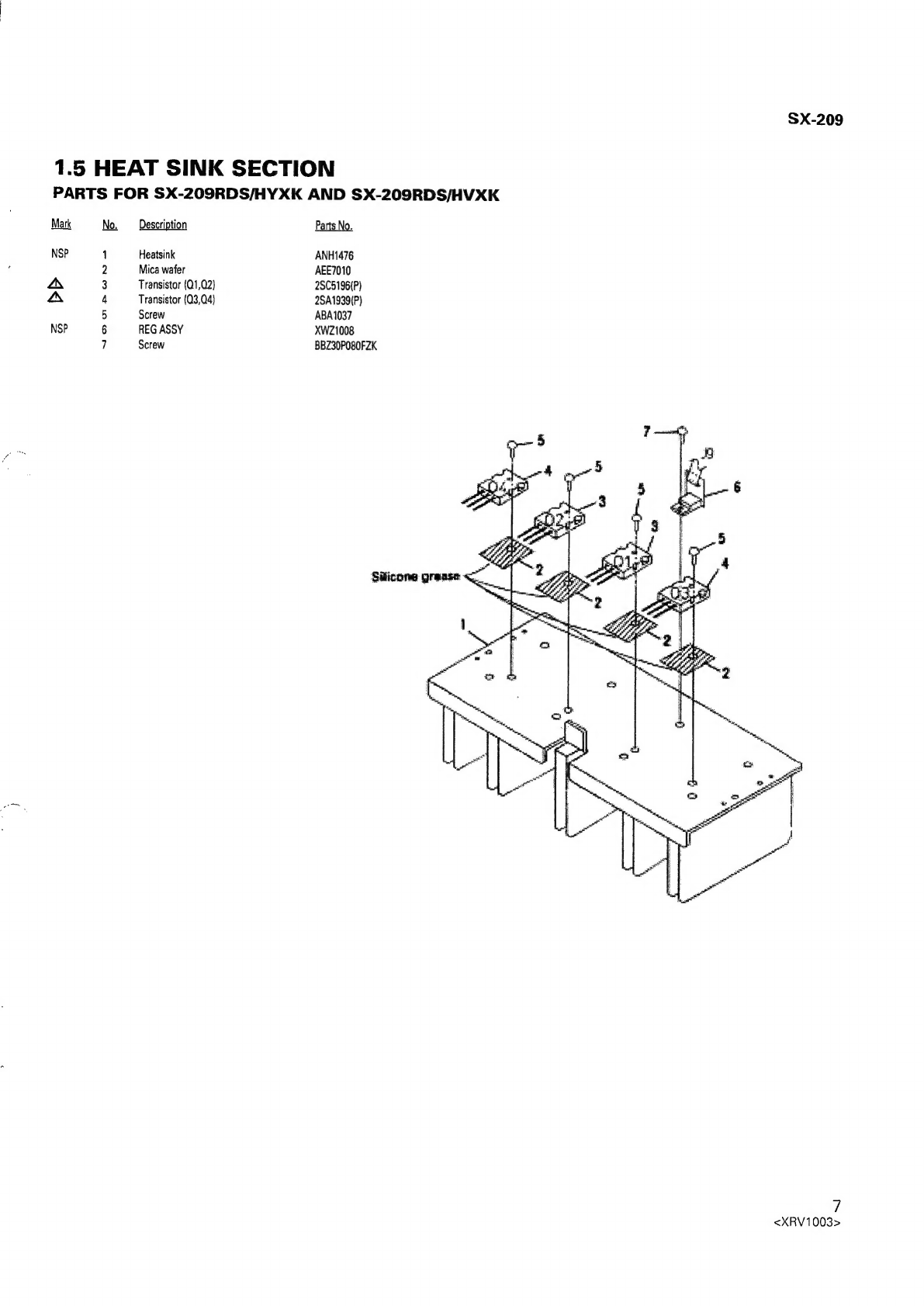
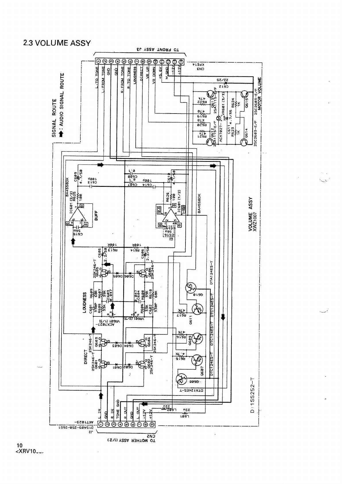
Pioneer SX-209RDS User manual
Other Pioneer Stereo Receiver manuals

Pioneer
Pioneer AVH-280BT/XNUC User manual

Pioneer
Pioneer DMH-2770NEX User manual

Pioneer
Pioneer AVH-120BT User manual

Pioneer
Pioneer VSX-405 User manual

Pioneer
Pioneer SX-1250 User manual

Pioneer
Pioneer DMH-1770NEX User manual

Pioneer
Pioneer XC-L5 User manual

Pioneer
Pioneer SX-2900 User manual

Pioneer
Pioneer SX-303 User manual

Pioneer
Pioneer DMH-ZF8550BT User manual

Pioneer
Pioneer SPH-EV093DAB User manual

Pioneer
Pioneer SX-450 User manual

Pioneer
Pioneer VSX-531D User manual

Pioneer
Pioneer LX-880 Service manual

Pioneer
Pioneer SX-2300 User manual

Pioneer
Pioneer SX-850 User manual

Pioneer
Pioneer SX-990 Setup guide

Pioneer
Pioneer SC-LX901 Installation guide

Pioneer
Pioneer AVH-X7800BT User manual

Pioneer
Pioneer VSX-515-K User manual


Popular Stereo Receiver manuals by other brands


Denon
Denon AVR-X7200W Service manual

Sony
Sony XAV-1500 operating instructions

Radio Shack
Radio Shack DX-399 owner's manual

Sony
Sony STR-DE535 - Fm Stereo/fm-am Receiver operating instructions

Yamaha
Yamaha MusicCast TSR-5B3D owner's manual

Sony
Sony STR-DE335 - Fm Stereo/fm-am Receiver operating instructions