manuals.online logo
Brands
  1. Home
  2. •
  3. Brands
  4. •
  5. Pioneer
  6. •
  7. Stereo Receiver
  8. •
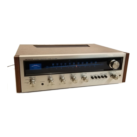
  9. Pioneer SX-980 User manual

Pioneer SX-980 User manual

AM/FM
STEREO
RECEIVER
X=9soO
¢
‘
_OPERATING
INSTRUCTIONS
a
|
_|
igen!
|
fsxsso
is
designed
to
operate
from
220V
or
240V
main.
Eat
dt
dee
oaitlie
|
ee
ee
tie
2
‘aes
oaon
a
Before
turning
on
the
power,
please
confirm
the
line
voltage
setting
indicated
on
the
rear
of
your
unit
corresponds
to
the
supply
voltage
in
your
area;
if
not,
change
the
setting
as
described
in
LINE
VOLTAGE
SELECTOR
SWITCH
on
page
19.
CONTENTS
Features:
eis
n
5
5
ea
ted,
ee
a
alee
eg
OS
A
ae
2
Installation
Cautions
................0.000.
3
Connection
Diagram
...............00000.
4
Connections
Antenna
and
Ground
Connections
............
8
Front
Panel
Facilities
Prior
to
Switching
Power
On...
..........04.
13
FM
Reception
...........
2.000000
0c
eee
13
AM
Reception
............0.
0000000
e
eae
13
Playing
Records
.................0200005
14
Using
the
Microphone
.................005
14
Using
the
AUX
jacks
................0000.
14
Effective
Operation...
.........00
00000
uae
15
Tape
Deck
Operations
................0005
16
Using
PREAMP
OUT
and
POWER
AMP
IN
Jacks
..
17
Specifications
Line
Voltage
Selector
Switch
Conditions
Frequently
Mistaken
for
Malfunction
.
.
peter
a
iat
eee
th
Ws
dens
et
ihe
FEATURES
Power
Amplifier
for
a
Continuous
Power
Output
of
80
Watts
Per
Channel
and
for
Ultra-Stable
Sound
Reproduction
@
The
adoption
of
a
single-stage
differential
amplifier
with
low-noise
dua!
transistors,
pre-driver
stage
a
current
mirror
load
and
an
SEPP
circuit
provides
a
bumper
power
output
of
80
watts
+
80
watts(
continuous
power
output
of
80
watts”
per
channel,
min.,
at
8
ohms
from
20
Hertz
to
20,000
Hertz
with
no
more
than
0.05%
total
har-
monic
distortion)
which
is
extremely
stable.
These
features
also
guarantee
a
stable
operation
at
all
times
from
low
outputs
to
high
outputs.
@
The
power
amplifier
is
configured
as
a
DC
power
ampli-
fier
with
the
capacitors
removed
from
the
NFB
circuit
for
a
flat
gain
response
all
the
way
from
the
lowest
of
the
low
frequencies
up
to
the
audio
frequencies.
At
the
same
time,
the
design
is
engineered
for
low
distortion
with
the
incorporation
of
newly
developed
power
transistors.
@
The
large-sized
transformer
with
its
superb
regulation
employ
two
18,000uF
large-capacity
electrolytic
capaci-
tors
in
the
power
supply
and
permit
high
sound
quality
even
at
lowest
frequencies.
IC-Based
FM
Tuner
with
High
Selectivity,
High
S/N
and
Low
Distortion
®
The
FM
front
end
incorporates
a
1-stage
RF
circuit
that
employs
a
4-gang
tuning
capacitor
and
a
dual-gate
MOS
FET
for
high
gain
and
low
noise.
This
config-
uration
excels
in
ridding
the
sound
of
undesirable
interference
for
impressive
statistics:
1.7uV
(IHF)
sensitivity,
more
than
100dB
spurious
response
ratio
and
more
than
90dB
image
response
ratio.
@
The
FM
IF
amplifier
combines
three
dual-element
phase-
linear
ceramic
filters
with
two
IC’s
which
contain
quadrature
detectors
for
a
high
selectivity
(80dB)
and
a
low
distortion
(MONO:
0.1%
at
1kHz).
@
The
stereo
demodulator
employs
an
NFB-type
PLL
MPX
IC
with
a
automatic
pilot
canceller
which
automatically
cancels
out
the
pilot
signals
without
reducing
the
high-end
frequency.
This
means
that
the
leak
carrier
level
is
amply
suppressed
for
a
tip-top
separation
and
flat
frequency
response
in
the
reproduction
frequency
band.
AM
Tuner
Includes
Newly
Developed
!C
The
tuned
AM
RF
amplifier
circuit
incorporates
a
newly
developed
high-sensitivity,
low-distortion
IC
and
2-gang
variable
capacitor.
These
contribute
to
enhanced
imaging
and
RF
interference
rejection
capabilities.
Since
the
optimum
AGC
voltage
is
supplied
to
each
section,
2
stable
reception
can
be
obtained
with
low
spurious
inter-
ference
and
distortion
even
in
high
field
strength
areas.
Precise
Record
Equalization
e@
A
balanced
power
supply
is
used
in
the
equalizer
ampli-
fier
to
obtain
a
maximum
allowable
input
of
200mVrms
(1kHz).
Low
distortion
record
playback
can
thus
be
enjoyed
even
with
high
output
phono
cartridges
and
music
sources
containing
large
peak
signals.
@
The
equalizer
elements
which
are
designed
to
produce
the
RIAA
characteristics
use
high-precision
parts
to
keep
the
equalizer
deviation
between
20Hz
—
20kHz
down
to
+0.2dB
for
faithful
sound
reproduction
from
records.
Other
Features
TURNOVER
switches:
These
switches
yield
variations
in
the
curves
of
the
tone
controls
when
they
are
operated
in
conjunction
with
the
other
bass
and
treble
tone
controls.
One
is
used
for
the
bass
and
the
other
for
the
treble,
thereby
allowing
plenty
of
variation
in
tone
control
adjust-
ment.
Highly
reliable
protection
circuitry:
In
order
to
protect
the
speakers
and
the
power
transistors,
this
receiver
features
a
newly
developed
protection
IC
as
well
as
a
special
muting
circuit
that
cuts
out
the
noise
produced
by
the
on/off
operation
of
the
power
switch.
Needless
to
say,
these
are
very
dependable
and
stable
protection
circuits.
In
addition,
there
is
an
inrush
current
suppressor
circuit
which
sup-
presses
surges
of
current
when
the
power
is
switched
on.
FM
25us
switch:
The
receiver’s
front
panel
is
equipped
with
a
de-emphasis
selector
switch
which
is
useful
when
the
receiver
is
tuned
into
an
FM
Dolby
station.
This
facilitates
operation
when
the
receiver
is
set
up
for
the
reception
of
an
FM
Dolby
broadcast.
TAPE
DUPLICATE
switch:
This
switch
allows
you
to
use
two
tape
decks
to
edit
or
duplicate
material
recorded
on
one
tape
to
another.
Duplication
from
an
open-reel
deck
to
a
cassette
deck,
for
example,
can
be
performed
in
a
one-touch
operation.
Power
meters:
Each
channel
has
its
own
power
meter
(0.01W
—
160W
display
range)
with
a
logarithmic
com-
pression
scale.
These
meters
feature
a
fast
response
speed,
and
they
enable
you
to
read
out
the
power
values
at
an
8-ohm
impedance
across
a
power
band
stretching
from
0.01W
up
to
the
maximum
output
of
the
receiver.
6kHz
(high)
and
15Hz
(low)
filter
switches:
Featured
are
a
filter
for
GdB/octave
attenuation
at
frequencies
below
15Hz
in
order
to
eliminate
ultra-low-range
noise
generated
by
warps
in
the
records,
and
also
a
6kHz
(6dB/oct
attenu-
ation)
filter
that
eliminates
high-range
noise
such
as
that
produced
by
scratches
on
the
records
and
hiss.
*Measured
pursuant
to
Federal
Trade
Commission's
Trade
Regulation
rule
on
Power
Output
Claims
for
Amplifiers.
ee
FONE
KT
--
FOR
USE
IN
UNITED
KINGDOM
OR
AUSTRALIA
CAUTION
240V
nected
to
the
terminal
which
is
marked
with
the
|
Mains
supply
voltage
is
factory
adjusted
at
240
letter
L
or
coloured
brown
or
red.
volts.
The
AC
Outlets
of
this
apparatus
have been
re-
moved
from
this
apparatus
in
order
to
comply
WARNING
with
U.K.
Safety
Regulation.
Ensure
that
your
THIS
APPARATUS
MUST
BE
EARTHED.
equipment
is
connected
correctly—if
you
are
in
IMPORTANT
doubt,
consult
a
qualified
electrician.
The
wires
in
this
mains
lead
are
coloured
in
ac-
Do
not
unscrew
the
bottom
plate
and
cabinet.
:
;
No
user
serviceable
parts
inside.
d
th
the
foll
de:
; :
ree
ht
Nae.
ia
sa
Always
disconnect
all
the
equipment
from
the
;
mains
supply
when
disconnecting
the
signal
Blue:
Neutral
leads.
The
Power
cord
should
be
connected
last,
make
sure
that
the
Power
switch
is
OFF.
Be
sure
the
appliance
connector
is
fully
inserted
into
the
AC
inlet.
Unplug
the
set
from
the
wall
socket
when
it is
not
to
be
used
for
an
extended
period
of
time.
Brown:
Live
As
the
colours
of
the
wires
in
the
mains
lead
of
this
apparatus
may
not
correspond
with
the
coloured
markings
identifying
the
terminals
in
your
plug
proceed
as
follows.
The
wire
which
is
coloured
green-and-yellow
must
be
connected
to
the
terminal
in
the
plug
FOR
YOUR
SAFETY
which
is
marked
by
the
letter
E
or
by
the
safety
1.
Insert
this
plug
only
into
effectively
earthed
earth
symbol
~
or
coloured
green
or
green-and-
three-pin
plug-socket
outlet.
yellow.
2.If
any
doubt
exists
regarding
the
earthing,
The
wire
which
is
coloured
blue
must
be
con-
consult
a
qualified
electrician.
nected
to
the
terminal
which
is
marked
with
the
3.
Extension
cords,
if
used,
must
be
three-core
letter
N
or
coloured
blue
or
black.
correctly
wired.
The
wire
which
is
coloured
brown
must
be
con-
INSTALLATION
CAUTIONS
To
ensure
the
best
sound
quality
and
trouble-free
operation,
avoid
setting
up
the
SX-980
in
any
of
the
locations
described
below.
Location
liable
to
downgrade
performance
Resulting
trouble
and
result
in
breakdowns
9
1.
Locations
exposed
to
direct
sunlight,
or
near
heaters.
1.
External
heat
causes
the
performance
of
the
circuit
parts
to
deteriorate,
and
operation
becomes
unstable.
2.
Locations
with
poor
ventilation,
or
with
high
humidity
or
2.
Cause
of
faulty
contact
in
input/output
terminals,
and
rust.
moisture
contents,
or
dusty
locations.
High
humidity
and
a
high
moisture
content
cause
deterioration
in
insulation.
There
is
also
the
danger
of
current
leakage
and
heat
generation
in
the
circuit
parts.
Dust
or
grease
in
the
rotat-
ing
parts
causes
the
parts
to
deteriorate.
3.
Locations
susceptible
to
vibration.
3.
These
locations
affect
the
precision
parts
adversely.
4.
Locations
where
an
AM
radio
or
TV
set
is
being
used
simulta-
4.
Mutual
interference
can
occur
from
the
oscillator
circuits
used
neously.
in
these
products.
Don’t
put
anything
on
the
top
of
the
receiver
because
high
power
receiver
will
produce
a
lot
of
heat.
Also
leave
sufficient
around
the
receiver
for
adequate
ventilation.
SL
mae
ee
Na
Ta
a
a
|
3
CONNECTION
DIAGRAM
FM
outdoor
antenna
T-type
FM
antenna
AM
outdoor
antenna
300
ohm
feeder
|
|
=
ee
be
ee
75
ohm
connector
plug
(
Ao)
Turntable
1
Ground
|
Ducne
Se
iane
wa
hee
(PHONO
1)
©)
F
5
r
©)
|§
CHOHCHES
4,
ese
elles)
°
©
KO)
|
RF
FAGHGHO
Ground
I
Output
|
(PHONO
2)
'
Cartridge
tape
Xx
Tape
deck
1
(TAPE
1)
Pe
Pe
ee
PRE/POWER
AMP
LINE
VOLTAGE
SELECTOR
SWITCH
The
bridge
connecting
plugs
between
PREAMP
OUT
Refer
to
page
19.
and
POWER
AMP
IN
jacks
should
always
be
left
in
Position
in
normal
use.
If
they
are
disconnected
or
removed
no
sound
will
come
from
the
speakers.
Always
be
sure
to
switch
off
the
power
supply
before
AC
INLET
attempting
to
remove
them.
Refer
to
the
section
Plug
the
AC
power
cord
into
this
socket.
“USING
THE
PREAMP
OUT
AND
POWER
AMP
IN
JACKS”
on
page
17.
AC
INLET
é
lO!
MMU
ISN
a@p)p
68
ry
Recording/Play
back
cord
= =
“DiNcord)
~~
~~~
™~
Left
Right
Speaker
systems
Output
(SPEAKERS
A)
Tape
deck
(TAPE
2)
Left
Right
Speaker
systems
(SPEAKERS
B)
3
|
CONNECTIONS
PRECAUTIONS
e
Set
the
POWER
switch
to
ON
only
when
you
have
completed
all
the
connections
of
the
stereo
system.
Always
set
this
switch
to
its
bottom
position
(OFF)
if
you
want
to
change
the
con-
nections.
e
All
the
receiver’s
jacks
are
aligned
for
easy
connection
in
two
rows:
the
top
row
for
L
(left
channel)
and
the
bottom
row
for
R
(right
chan-
nel).
Always
connect
L
to
L
and
R
to
R
with
the
audio
component
output
and
input
jacks.
@
Make
sure
that
the
connections
are
secure.
Improper
connections
can
generate
noise
and
cause
the
sound
to
be
cut
off.
SPEAKER
SYSTEMS
The
receiver
is
provided
with
two
sets
of
SPEAK-
ERS
output
terminals.
Use
the
A
set
when
connecting
only
one
set
of
speakers.
Viewed
from
the
front,
the
R
(right
channel)
SPEAKERS
terminals
are
on
the
right
and
the
L
(left
channel)
SPEAKERS
terminals
are
on
the
left.
Connect
the
left
channel
speaker
to
the
L
terminals
and
the
right
channel
speaker
to
the
R
terminals.
The
red
L
and
R
SPEAKERS
terminals
have
a
plus
polarity
and
the
black
terminals
have
a
minus
polarity
just
like
the
speaker
systems
themselves.
When
connecting,
always
connect
minus
to
minus
and
plus
to
plus
(Fig.
1).
RIGHT
SPEAKER
LEFT
SPEAKER
SYSTEM
SYSTEM
.
Fig.
1
NOTE:
If
you
want
to
use
two
sets
of
speaker
systems,
make
sure
that
the
impedance
of
each
system
is
8
ohms
or
more.
If
the
impedance
is
less
than
8
ohms,
the
protective
circuitry
will
be
actuated
when
the
volume
is
turned
up
and
you
will
not
be
able
to
enjoy
proper
stereo
perform-
ance,
Connecting
the
speaker
lead
wires
to
the
SPEAKERS
terminals
(Fig.
2)
1.
Strip
about
10mm
of
the
insulation
from
the
end
of
the
speaker
lead
wires.
If
the
conductor
is
stranded,
twist
the
strands
together
so
that
they
do
not
come
into
contact
with
other
terminals.
2.
Depress
the
terminal
buttons
and
insert
the
lead
wires
into
the
terminal
holes.
8.
Release
the
buttons
and
check
that
the
lead
wires
are
secure.
SPEAKERS
terminals
Speaker
system
Fig.
2
NOTES:
1.
The
high
output
power
of
this
receiver
requires
that
the
speaker
lead
wires
have
an
ample
current
carrying
capacity.
Use
wires
with
a
high
capacity
and
connect
them
securely.
If
you
use
low
capacity
wires
and
do
not
connect
them
properly,
the
reproduced
sound
will
be
adversely
affected
and
heat
generation
or
short
circuits
may
be
caused.
2.
This
receiver
delivers
a
high
output
power
and
so
make
sure
that
you
use
speakers
with
a
high
allowable
input.
TURNTABLE
CONNECTIONS
Connect
the
output
cords
of
a
turntable
using
a
moving
magnet
(MM)
cartridge
to
the
PHONO
1
input
jacks.
Connect
the
ground
lead
of
the
turn-
table
to
the
GND
terminal
on
the
receiver
(Fig.
3).
NOTES:
e
In
addition
to
turntables
using
MM
cartridges,
there are
others
that
employ
induced
magnet
(IM),
moving
iron
(MI)
and
high-output
moving
coil
(MC)
cartridges.
If
you
intend
to
use
a
turntable
with
a
low-output
MC
cartridge,
always
provide
a
special
MC
cartridge
boost-
ing
transformer
or
head
amplifier.
e
Connect
your
second
turntable
to
the
PHONO
2
input
Jacks.
e
If
your
turntable
is
fitted
with
two
tonearms,
the
output
cords
for
each
of
the
tonearms
should
be
connected
to
the
PHONO
I
and
PHONO
2
input
jacks.
Fig.
3
TAPE
DECK
CONNECTIONS
The
receiver
is
provided
with
two
sets
of
recording
(TAPE
REC)
output
jacks
and
two
sets
of
play-
back
(TAPE
PLAY)
input
jacks.
Connect
each
of
the
jacks
in
the
following
way
using
the
connecting
cords
which
come
with
the
tape
deck.
The
upper
row
of
jacks
is
for
the
left
channel
(L)
and
the
lower
row
for
the
right
channel
(R)
(Fig.
4).
Connections
for
recording
Connect
the
recording
input
jacks
(LINE
INPUT)
on
the
tape
deck
to
the
TAPE
1
REC
jacks
on
the
receiver.
Connections
for
playback
Connect
the
playback
output
jacks
(LINE
OUT-
PUT)
on
the
tape
deck
to
the
TAPE
1
PLAY
jacks
on
the
receiver.
NOTE:
Connect
your
second
tape
deck
to
the
TAPE
2
jacks
(REC,
PLAY).
PIONEER
SX-980
Tape
deck
1
Recording
connections
Connections
using
the
recording/playback
connector
(DIN
cord)
If
your
tape
deck
is
equipped
with
a
recording/
playback
connector
(DIN-type),
use
the
optional
recording/playback
cord
to
connect
this
connector
with
the
TAPE
2
REC/PLAY
jack
on
the
receiver.
This
means
that
the
deck
and
receiver
are
now
set
up
for
both
recording
and
playback
(Fig.
5).
In
such
cases,
do
not
connect
pin
cords
(ordinary
pin
plug
cords)
to
the
TAPE
2
REC
and
PLAY
jacks.
REC/PLAY
jack
REC/PLAY
cord
TAPE
2:
REC
PLAY
|
®
Tape
deck
2
ar
Fig,
5
ANTENNA
AND
GROUND
CONNECTIONS
FM
ANTENNA
CONNECTIONS
The
signals
transmitted
by
an
FM
broadcasting
station
inevitably
become
weak
when
received
behind
mountains,
between
buildings
and
inside
reinforced
concrete
structures.
In
weak-signal
areas,
signals
which
are
reflected
off
mountains
and
other
obstacles
in
their
path
may
be
picked
up
by
the
antenna,
which
causes
a
multipath
effect.
This
adversely
affects
the
sound
received.
This
is
why
it
is
necessary
to
choose
an
antenna
and
an
installation
location
which
are
best
suited
to
cope
with
the
ambient
conditions
and
the
strength
of
the
signals.
Special
FM
antennas
It
is
recommended
that
you
use
a
special
FM
antenna
in
order
to
obtain
input
signals
which
will
allow
your
receiver
to
display
its
capabilities
to
the
full.
@
When
installing
your
antenna,
refer
to
the
instructions
in
‘FM
RECEPTION’
on
page
13
and
determine
in
which
direction
the
antenna
should
point
for
the
best
reception,
all
the
while
listening
to
a
broadcast
to
check
the
reception.
Mount
the
antenna
securely.
@
In
accordance
with
the
application
of
the
antenna,
use
a
75-ohm
coaxial
cable
or
a
300-
ohm
feeder
to
connect
the
antenna
to
the
receiver.
75-ohm
coaxial
cable:
As
shown
in
Fig.
6,
connect
the
cable
to
the
752
UNBAL
terminal
of
the
receiver.
This
cable
is
used
in
locations
near
roads
with
a
great
deal
of
traffic,
and
near
overhead
high-tension
power
lines
which
generate
a
lot
of
noise.
It
is
also
used
when
the
antenna
and
the
receiver
are
far
apart.
300-ohm
feeder:
As
shown
in
Fig.7,
connect
the
feeder
to
the
83002
BAL
terminals.
Use
it
when
there
is
little
external
noise
and
when
the
antenna
and
the
receiver
are
not
far
apart.
NOTE:
Consult
your
nearest
PIONEER
dealer
concerning
the
special
FM
antenna
and
the
75-ohm
coaxial
cable.
T-type
antenna
When
the
broadcasting
station
is
located
nearby
and
when
the
FM
signals
are
strong
in
wooden
frame
buildings
and
others,
you
can
use
the
accessory
T-type
antenna
(Fig.7).
As
shown
in
Fig.
7
connect
the
end
of
the
T-type
antenna
to
the
300-ohm
terminal.
Spread
the
two
arms
of
the
antenna
horizontally
and
while
listen-
ing
to
an
FM
station,
rotate
the
antenna
through
180
degrees
and
position
it
for
the
best
reception.
Tape
the
antenna
to
a
wall
or
ceiling.
FM
outdoor
antenna
$X-980
Antenna
terminals
FM
outdoor
antenna
T-type
antenna
300-ohm
feeder
AM
ANTENNA
CONNECTION
Move
the
AM
bar
antenna
on
the
rear
panel
of
the
receiver
and
find
the
best
reception
position,
all
the
while
following
the
instructions
outlined
on
page
13
under
‘AM
RECEPTION.’
Fig.
8
NOTES:
e
The
AM
bar
antenna
on
the
receiver’s
rear
panel
displays
directivity
and
so
some
stations
may
be
poorly
received.
In
such
cases,
change
the
installation
direc-
tion
of
the
receiver.
e
If
the
receiver
is
installed
right
up
against
a
wall
in
a
reinforced
concrete
building,
the
reception
may
be
adversely
affected.
Therefore,
it is
a
good
idea
to
erect
an
indoor
AM
antenna.
e
If
you
still
cannot
obtain
good
reception
even
by
moving
the
AM
bar
antenna,
erect
an
indoor
AM
antenna
with
a
vinyl
insulated
wire
(about
5-6
meters
long).
As
shown
in
Fig.9,
connect
the
lead
wire
to
the
AM
antenna
terminal,
and
tape
it
to
the
wall
or
ceiling.
e
If
you
live
in
an
area
where
the
reception
is
poor
even
if
you
erect
an
indoor
AM
antenna,
use
a
tree
to
erect
an
outdoor
AM
antenna
with
a
vinyl
insulated
wire
(Fig.
9).
AM
outdoor
antenna
Indoor
antenna
(vinyl
insulated
wire)
SX-980
Antenna
terminals
Fig.
9
PIONEER
GROUNDING
As
shown
in
Figs.6
&
7,
connect
a
ground
wire
to
the
GND
terminal
on
the
receiver
for
maximum
safety
and
noise
reduction.
Never
make
this
con-
nection
near
gas
pipes
and
other
potentially
dangerous
locations.
FM
ANTENNA
LOCATION
It
is
important
to
choose
with
care
the
locations
where
you
will
install
your
FM
antenna
for
the
stable
reception
of
the
signals
from
FM
broadcast-
ing
stations
and
for
superior
sound
reproduction.
Bear
in
mind
the
following
points
and
determine
the
optimum
location
(height
and
direction).
1.
The
ideal
place
for
the
antenna
is
somewhere
where
it
can
pick
up
the
signals
transmitted
from
the
FM
broadcasting
station
antenna
directly.
Locations
where
these
signals
cannot
be
picked
up
directly
because
of
obstacles
in
their
path
or
because
the
receiver’s
antenna
is
located
in
a
low
building
surounded
by
higher
buildings,
are
affected
by
the
multipath
effect
caused
when
signals
are
reflected
off
these
obstacles
or
buildings.
In
such
places,
the
sound
will
be
distorted
and
the
separation
between
the
left
and
right
channels
will
deteriorate.
Choose
a
height
and
a
direction
for
the
antenna
where
the
multipath
effect
will
be
minimal.
2.
Erect
your
antenna
as
far
away
as
possible
from
roads
so
that
there
is
no
interference
from
auto-
mobile
ignition
noise,
and
also
from
high-tension
power
lines
and
neon
signs.
38.
Keep
your
antenna
at
least
two
meters
away
from
sheet-metal
roofs,
concrete
buildings
and
TV
antennas.
Station
direction
More
than
4
meters
(15
ft.)
above
ground
Feeder
or
cable
should
not
directly
contact
other
structures.
Keep
cabling
as
short
as
possible
Select
location
away
from
traffic
noise
and
with
clear
line
of
sight
-
|
FRONT
PANEL
FACILITIES
POWER
SWITCH
POWER
METERS
Flip
this
switch
to
the
ON
position
to
supply
power
to
the
These
power
meters
allow
you
to
read
out
the
rated
stereo
receiver.
There
will
be
a
short
delay
when
it
is
set
power
level
when
speakers
with
a
nominal
impedance
of
to
ON,
because
the
muting
circuit
has
been
actuated
to
8
ohms
are
connected
to
the
receiver’s
speaker
terminals.
suppress
the
unpleasant
noise
that
is
sometimes
generated
NOTE:
when
the
power
is
switched
on
and
off.
These
values
are
related
to
the
impedance
of
the
speakers
and
they
vary
according
to
the
frequency.
In
order
to
find
out
the
exact
output
level,
connect
an
PHONES
JACK
8-ohm
dummy
load
instead
of
the
speakers.
Plug
the
headphones
into
this
jack
when
you
want
to
listen
through
your
stereo
headphones.
Release
both
SPEAKERS
buttons
if
you
want
to
listen
to
the
sound
through
your
headphones
only.
(This
means
that
both
buttons
will
be
released).
FUNCTION
INDICATOR
MEMORY
MARKERS
These
are
very
convenient
for
frequent
tuning
in
to
the
same
broadcasting
station.
TREBLE
wee
i
TRROven
TURNOVER
Lich
F
OLUME,
2
JPL
5
L
BOOHz
é
4 2
2
Y
pahte
:
L
3
3
STERE:
la
a
a
ON
S
,,
ON ON
ON
MONO
ON
LEFT
RuGHT
oo
¢
|
|
SPEAKERS
BUTTONS:
Press
the
button
corresponding
to
the
speakers
connected
to
the
SPEAKERS
terminals
(A
or
B)
on
the
rear
panel.
You
can
press
both
of
these
buttons
to
listen
to
sound
from
two
pairs
of
speaker
systems
at
the
same
time.
MUTING
SWITCH—————----
Set
this
switch
to
the
—20dB
position
to
attenuate
the
audio
output
indicated
by
the
VOLUME
control
by
20dB.
There
is
no
need
to
adjust
the
VOLUME
control
if
you
use
this
switch
when
turning
down
the
audio
output
temporarily
and
when
changing
over
records
or
tapes.
For
further
details,
refer
to
page
15.
BALANCE
CONTROL
Use
this
control
to
balance
the
volume
of
the
left
and
right
channels.
First,
however,
set
the
MODE
switch
to
~VOLUME
CONTROL
MONO,
and
adjust
so
that
the
sound
appears
to
come
Use
this
control
to
adjust
the
output
level
to
the
speakers
from
somewhere
exactly
between
the
two
speakers.
If
the
and
headphones.
Turn
it
clockwise
to
increase
the
output
sound
appears
to
be
jouder
on
the
right,
it
means
that
the
ievel.
No
sound
will
be
heard
if
you
set
it
to
o.
The
scale
volume
of
the
right
channel
is
higher.
Turn
the
BALANCE
is
graduated
in
dB
which
indicate
the
attenuation
when
control
to
the
left
and
adjust.
Conversely,
if
the
sound
the
maximum
output
level
is
OdB.
appears
to
be
louder
on
the
left,
it
means
that
the
volume
of
the
left
channel
is
higher.
Therefore,
turn
the
BALANCE
control
to
the
right
and
adjust.
After
adjust-
ing,
return
the
MODE
switch
to
STEREO.
10
[Continued
next
page
|
ee
(ONC
CT.
TONE
SWITCH
Set
this
switch
to
ON
when
adjusting
the
BASS
and
TREBLE
controls.
In
the
OFF
position,
it
causes
the
amplifier
to
operate
with
a
flat
frequency
response.
rFUNCTION
BUTTONS
|
Ee
Press
the
function
button
which
corresponds
to
the
pro-
gram
source.
Turn
the
VOLUME
control
down
first
before
selecting
a
different
function
button
while
the
sound
from
one
program
source
is
being
reproduced.
FM..........
Press
this
button
for
FM
broadcasts.
The
FM
STEREO
indicator
lights
up
when
the
receiver
is
tuned
into
an
FM
stereo
broadcast.
The
sound
is
automatically
received
monophonical-
ly
during
FM
monophonic
broadcasts.
TREBLE
ee
TURNOVER
BASS
AND
TREBLE
CONTROLS—
Use
these
controls
to
adjust
the
bass
and
the
treble.
If
you
set
the
TONE
switch
to
ON
and
turn
the
BASS
control
to
the
right
from
its
center
position,
you
will
be
able
to
emphasize
the
sound
in
a
frequency
range
which
is
lower
than
that
selected
by
the
BASS
TURNOVER
switch.
Conversely,
turning
this
control
from
the
center
position
to
the
left
will
attenuate
the
sound.
You
can
use
the
TREBLE
control
to
adjust
the
sound
ina
frequency
higher
than
that
selected
by
the
TREBLE
TURNOVER
switch.
For
further
details,
refer
to
“TURNOVER
SWITCHES”
on
page
15.
BASS
TURNOVER
SWITCH
Use
this
switch
to
change
over
the
frequency
at
which
the
sound
adjustment
with
the
BASS
control
is
starting
to
take
effect.
Select
200Hz
or
400Hz
in
accordance
with
the
characteristics
of
your
listening
room
and
of
your
speakers,
and
with
your
general
preference.
Press
this
button
for
AM
broadcasts.
Press
this
button
when
listening
to
an
audio
component
connected
to
the
AUX
input
jacks.
Press
this
button
when
playing
a
record
on
the
turntable
connected
to
the
PHONO
2
jacks,
or
when
using
a
microphone
which
you
have
plugged
into
the
MIC
jack.
Press
this
button
when
playing
a
record
on
the
turntable
connected
to
the
PHONO
1
jacks.
PHONO
2/MIC..
PHONO
1
NOTES:
1.
Unplug
the
microphone
from
the
MIC
jack
when
you
do
not
intend
to
use
the
microphone
otherwise
you
will
not
be
able
to
use
the
PHONO
2
jacks.
2.
Only
one
function
button
should
be
pressed
at
a
time.
MOME
LOUDNESS
BALANCE
FB.
for
=
38
QPIONEER
STEREO
RECEIVER
SX-SBO
TAPE
MONITOR
SWITCHES
(1,
2)
Set
switch
1
to
ON
with
a
tape
deck
which
is
connected
to
the
TAPE
1
jacks
(REC
and
PLAY)
when
you
want
to
monitor
the
playback
or
recording
of
a
tape.
The
tape
on
a
deck
which
is
connected
to
the
TAPE
2
jacks
(REC
and
PLAY)
can
be
similarly
monitored
by
setting
switch
2
to
ON.
For
further
details,
refer
to
“TAPE
DECK
OPERA-
TIONS”
on
page
16.
NOTE:
Set
these
switches
to
the
upper
(off)
position
when
listening
to
records
or
a
broadcast.
L_TREBLE
TURNOVER
SWITCH
Use
this
switch
to
change
over
the
frequency
at
which
the
sound
adjustment
with
the
TREBLE
control
is
starting
to
take
effect.
Select
2.5kHz
or
5kHz
in
accordance
with
the
characteristics
of
your
listening
room
and
of
your
speakers,
and
with
your
general
preference.
11
TUNING
METER
When
tuning
in
to
an
FM
station,
the
optimum
reception
position
is
indicated
when
the
meter
pointer
deflects
to
dead
center.
Check
that
the
SIGNAL
meter
pointer
has
i
deflected
as
far
to
the
right
as
possible.
SIGNAL
METER
When
tuning
in
to
an
AM
or
FM
station,
the
optimum
reception
position
is
indicated
by
the
maximum
deflec-
tion
of
the
meter
pointer
to
the
right.
FM
MUTING
BUTTON
ON
(released
position)
..
.
Release
this
button
to
sup-
press
unpleasant
inter-station
noise
when
tuning
between
FM
stations.
Depress
this
button
to
pick
up
weak
stations.
OFF
(depressed
position)
.
STEREO
INDICATOR
This
indicator
lights
up
when
the
receiver
is
tuned
to}
receive
a
stereo
broadcast.
“FILTER
BUTTONS
|
15Hz
..
When
this
button
is
pressed,
a
6dB/oct
attenua-;
tion
can
be
provided
for
frequencies
below
15Hz.
This
means
that
you
can
cancel
out
noise
in
the
ultra-low
frequencies
which
is
generated
by
low-pitched
rumble
from
a
turntable
and
other
forms
of
distortion.
Although
this
noise
cannot
be
heard,
it
can
generate
intermodula-|
tion
distortion
and
damage
the
speakers.
H
|
6kHz
..
Press
this
button
to
provide
a
6dB/oct
attenua-
tion
at
frequencies
above
6kHz.
Set
it
to
this
position
when
you
find
high-frequency
noise,
|
such
as
that
from
scratched
records,
unpleasant.
}
heeercmenre
rere
ae
FM
25us
BUTTON
Press
this
button
when
listening
to
a
Dolby*
FM
broad-
cast;
otherwise
keep
this
button
at
the
released
position.
For
further
details,
refer
to
page
15.
TUNING
KNOB
pusucare
MONT,
Vou
Pay
44
3a,
1
20.
a
STERF
a
ONO
f6;
FST
-
=
o
08
a
STEREO
RECEIVER
SX-9B0
MIC
JACK
Plug
your
microphone
into
this
jack.
The
microphone
signals
are
reproduced
in
mono
through
the
left
and
right
speakers.
NOTE:
A
high
impedance
(approx.
50
kilohms)
dynamic
type
microphone
with
a
standard
plug
can
be
connected
to
this
jack.
Use
this
to
tune
in
to
broadcasting
stations.
Select
the
station
and
tune
for
optimum
reception
by
observing
the
SIGNAL
meter
for
AM
stations
and
both
the
SIGNAL
and
TUNING
meters
for
FM
stations.
r—TAPE—,
MODE
LOUDNESS:
3%
ANCE
Gt
i
LOUDNESS
SWITCH
Set
this
switch
to
ON
when
listening
at a
low
volume.
The
frequency
response
of
the
human
ear
varies
according
to
the
listening
volume,
and
setting
this
switch
to
the
ON
position
compensates
for
hearing
response
by
emphasizing
the
bass
and
treble.
“~MODE
SWITCH
Use
this
switch
for
selecting
mono
or
stereo
performances.
STEREO:
Set
to
this
position
for
normal
stereo
opera-
tion.
MONO:
When
set
to
this
position,
the
left
and
right
channel
signals
will
be
mixed
and
reproduced
monophonically
from
both
speaker
systems.
-——-
TAPE
DUPLICATE
SWITCH
Set
this
switch
to
ON
when
you
want
to
duplicate
or
edit
a
pre-recorded
tape
using
two
tape
decks.
For
further
details,
refer
to
“TAPE
DECK
OPERATIONS”
on
page
16.
12
*
The
word
“Dolby”
is
a
trademark
of
Dolby
Laboratories
Inc.
}
:
]
a
a
aN
ES
6)
AKC
Te
FM
RECEPTION
P
P
RIOR
TO
SWITCHING
OWER
ON
Before
switching
the
power
on,
set
the
various
controls
as
fol
1.
2.
lows:
Set
the
two
FILTER
buttons
to
the
released
positions.
Press
the
SPEAKERS
button
that
corresponds
to
the
speaker
system
which
is
connected
to
the
SPEAKERS
terminals
on
the
rear
panel.
.
Set
the
FM
25us
button
to
the
released
posi-
tion.
.
Set
the
FM
MUTING
button
to
the
released
position
(ON).
.
Set
the
VOLUME
control
to
the
©
position.
.
Set
the
BALANCE
control
to
the
center
posi-
tion.
.
Set
the
MODE
switch
to
STEREO.
.
Set
the
TAPE
MONITOR
switches
to
the
upper
positions
(OFF).
.
Set
the
DUPLICATE
switch
to
the
upper
posi-
tion
(OFF).
.
Set
the
TONE
switch
to
OFF.
.
Set
the
MUTING
switch
to
the
upper
position
(OFF).
PROTECTION
CIRCUIT
For
some
6
to
10
seconds
after
the
receiver
is
switched
ON,
no
sound
will
be
heard.
This
is
due
to
the
operation
of
protection
circuits
which
are
designed
to
safeguard
transistors
and
speakers
from
possible
damage
due
chiefly
to
switching
transients,
etc.
Should
|
the
receiver
remain
silent
for
considerably
longer
than
this,
switch
off
and
check
the
Speaker
system
connections.
Should
the
receiver
suddenly
go
silent
while
you
are
listening
to
it,
and
a
continuous
series
of
“clicks”
can
be
heard
from
relay
contacts
opening
and
closing
within
the
receiver,
this
can
be
an
indication
of
a
short
circuit
in
the
speaker
system
connections.
Switch
off,
and
re-check
the
speaker
system
impedances,
etc.
The
protection
circuit
re-sets
itself
automat-
ically,
so
that
normal
operation
is
resumed
as
soon
as
the
fault
is
corrected.
A
2.
3.
Depress
the
FM
function
button.
Slightly
turn
the
VOLUME
control
clockwise
direction
to
obtain
the
sound.
Select
the
broadcasting
station
with
the
tuning
knob.
Adjust
so
that
the
signal
meter
pointer
deflects
as
far
to
the
right
as
possible
and
the
tuning
meter
pointer
is
centered,
as
indicated
in
Fig.
10.
Press
the
FM
MUTING
button
if
the
signals
from
the
station
are
weak.
If
the
program
is
being
broadcast
in
stereo,
the
STEREO
indicator
will
come
on.
.
Adjust
the
volume
with
the
VOLUME
control.
.
To
adjust
the
tone,
first
set
the
TONE
switch
to
ON,
and
then
adjust
the
BASS
and
TREBLE
controls
for
the
preferred
bass
and
treble
levels.
Fig.
10
AM
RECEPTION
ray
.
Depress
the
AM
function
button.
.
Slightly
turn
the
VOLUME
control
clockwise
direction
to
obtain
the
sound.
.
Turn
the
tuning
knob
to
select
a
station.
The
best
reception
is
obtained
when
the
signal
meter
pointer
deflects
to
the
extreme
right
(see
Fig.
11).
4,
Adjust
the
volume
with
the
VOLUME
control.
5.
To
adjust
the
tone,
first
set
the
TONE
switch
to
ON,
and
then
adjust
the
BASS
and
TREBLE
controls
for
the
preferred
bass
and
treble
levels.
Fig.
11
NOTE:
If,
when
listening
to
either
an
FM
or
AM
broadcast,
your
listening
pleasure
is
seriously
affected
by
poor
sensitivity
or
strong
interference,
refer
to
the
section
“ANTENNA
AND
GROUND
CONNECTIONS”
on
page
8,
and
make
any
necessary
changes.
13
PLAYING
RECORDS
1.
If
your
turntable
is
connected
to
the
PHONO
1
input
jacks,
depress
the
PHONO
1
function
button.
If
it
is
connected
to
the
PHONO
2
input
jacks,
depress
the
PHONO
2
function
button.
2.
Operate
the
turntable
to
play
the
record.
8.
Adjust.
the
volume
with
the
VOLUME
control.
4.
To
adjust
the
tone,
first
set
the
TONE
switch
to
ON,
and
then
adjust
the
BASS
and
TREBLE
controls
for
the
preferred
bass
and
treble
levels.
Precautions
when
playing
records
e
Lower
the
stylus
gently
onto
the
surface
of
the
record.
It
is
a
good
idea
to
set
the
MUTING
switch
to
—20dB
or
to
turn
the
volume
down
when
lowering
the
stylus
onto
the
record.
@
Depress
the
15Hz
button
if
there
is
a
great
deal
of
noise
or
if
the
speaker
cone
paper
is
seen
to
be
moving
despite
the
fact
that
you
cannot
hear
the
sound
during
a
performance.
e
Do
not
cause
the
turntable
to
vibrate
while
a
record
is
being
played
since
this
will
cause
the
stylus
to
jump
and
scratch
the
record.
Do
not
turn
off
the
power
if
the
stylus
is
still
tracing
grooves
on
the
record.
USING
THE
MICROPHONE
1.
Connect
the
microphone
to
the
MIC
jack.
2.
Depress
the
PHONO
2/MIC
function
button.
3.
Adjust
the
sound
level
by
turning
the
VOLUME
contro!
gradually
to
the
right.
NOTES:
1.
Under
certain
conditions,
microphones
are
liable
to
give
rise
to
howl
or
feedback
noise.
Take
care
not
to
raise
the
volume
too
much
when
the
microphone
is
close
to
the
speaker
systems
or
in
a
room
with
a
great
deal
of
resonance.
It
is
a
good
idea
to
set
the
BASS
and
TREBLE
controls
to
their
center
positions
or
switch
the
TONE
switch
to
the
OFF
position.
2.
You
cannot
use
the
microphone
to
perform
mixing
operations
with
other
program
sources.
3.
You
should
unplug
the
microphone
jack
when
not
using
the
microphone,
otherwise
you
cannot
use
the
turntable
connected
to
PHONO
2
jacks.
4.
You
should
use
high
impedance
(approx.
50
kilohms)
microphones
of
the
dynamic
type,
with
standard
6mm
diameter
phones
plug.
14
Microphone
Fig.
12
USING
THE
AUX
JACKS
You
can
connect
an
8-track
cartridge
tape
player,
TV
tuner,
second
tuner
or
tape
deck
playback
output
to
these
jacks.
(See
Fig.
13).
PROCEED
AS
FOLLOWS:
1.
Depress
the
AUX
function
button.
2.
Operate
the
audio
component
which
you
have
connected
to
the
AUX
jacks.
3.
Adjust
the
volume
with
the
VOLUME
control.
4.
To
adjust
the
tone,
first
set
the
TONE
switch
to
ON,
and
then
adjust
the
BASS
and
TREBLE
controls
for
the
preferred
bass
and
treble
levels.
Cartridge
tape
AUX
input
jack
EFFECTIVE
OPERATION
TURNOVER
SWITCHES
As
shown
in
Fig.
14,
the
receiver
adopts
a
tone
control
system
that
combines
the
BASS
and
TREBLE
controls
with
two
TURNOVER
switches
which
are
used
to
select
the
frequency.
Select
the
frequency
with
the
TURNOVER
switches
and
then
enhance
or
attenuate
the
sound
in
the
lower
(or
higher)
frequencies
with
the
BASS
(or
TREBLE)
controls.
oo
—
TREBLE
TURNOVER
Base
fe
TURNOVER
4Q0Hz
Reig
TONE
eta
2.5kHz
2O0Hz
SkHz
2
2 2 2
Ft
3
OFF
3
3
a
a
ON
a
a
be
5 S 5
eS
=
ar
Fig.
14
For
instance,
if
the
BASS
TURNOVER
switch
is
set
to
400Hz
(see
Fig.
15),
the
bass
covers
a
wide
frequency
spectrum
and
can
be
enhanced
(or
reduced)
with
large
gain
per
step
of
the
BASS
control.
For
this
reason,
the
reproduced
sound
sometimes
seems
unnatural
depending
on
the
program
source,
but
this
can
be
remedied
by
setting
the
switch
to
200Hz.
H
ba,
‘
ibe
pee
'
|
BASS
TURNOVER
TREBLE
TURNOVE
a
25kHzZ
LEVEL
(dB)
10
100
200
400
1“
2.5m
Sk
10%
100%
FREQUENCY
(Hz)
A
Fig.
15
VOLUME
CONTROL
AND
MUTING
SWITCH
The
VOLUME
control
scale
is
directly
calibrated
in
dB.
By
adjusting
it
in
combination
with
the
MUTING
switch,
it
is
possible
to
adjust
the
attenu-
ation
more
finely
across
a
very
wide
range.
The
attenuation
(volume)
is
equal
to
the
VOLUME
control
indication
plus
20dB.
@®
One
convenient
application
of
the
MUTING
Switch
is
for
temporarily
reducing
the
volume
while
changing
records,
tapes
or
for
other
applications.
This
eliminates
the
need
for
con-
tinual
re-adjustment
of
the
VOLUME
control.
(Er
ee
ee
§
>)
ONC
CTS
e
With
late-night
listening
or
at
other
times
when
low
volumes
are
used,
precise
adjustment
becomes
difficult
when
the
VOLUME
control
is
near
the
~
position.
In
these
cases,
it is
conve-
nient
to
first
set
the
MUTING
switch
to
-20dB
and
then
adjust
the
VOLUME
control.
VOLUME
MUTING
~~
200B
RECEPTION
OF
FM
DOLBY
BROADCASTS
If
you
live
in
an
area’
where
you
can
receive
FM
Dolby
broadcasts,
you
can
listen
in
if
you
connect
an
optional
Dolby
adaptor
to
the
TAPE
2
jacks.
1.
Connect
the
Dolby
adaptor
to
the
TAPE
2
jacks
(REC,
PLAY),
as
shown
in
Fig..17.
.
Depress
the
FM
25uS
button.
.
Set
the
TAPE
MONITOR
2
switch
to
ON.
.
Operate
the
Dolby
adaptor.
.
Depress
the
FM
function
button
and
tune
in
to
the
Dolby
broadcast
with
the
tuning
knob.
For
reception,
refer
to
““FM
RECEPTION”
since
the
procedure
is
the
same.
Fig.
16
oo
®
bd
NOTES:
e
For
detailed
instructions
on
connections
and
the
handling
of
the
Dolby
adaptor,
refer
to
its
operating
instructions.
e
When
you
are
not
listening
to
an
FM
Dolby
broadcast,
return
the
FM
25uS
button
and
the
TAPE
MONITOR
2
switch
to
their
original
positions.
SX-980
Ss
-----
Se
«A
_————
nO.
Jpaovo
Ortee
Os
Dolby
adaptor
or
yor"
7
Fig.
17
15
TAPE
DECK
OPERATIONS
PLAYBACK
Proceed
as
follows
when
playing
back
pre-recorded
music
tapes
available
on
the
open
market,
and
tapes
on
which
you
have
recorded
programs:
1.
As
shown
in
Fig.
18,
set
the
TAPE
MONITOR
switch
1
to
ON
if
the
tape
deck
is
connected
to
the
TAPE
1
jacks.
Set
the
TAPE
MONITOR
switch
2
to
ON
if
it
is
connected
to
the
TAPE
2
jacks.
2.
Operate
the
tape
deck
controls
for
playback.
8.
Adjust
the
volume
with
the
VOLUME
control.
4.
To
adjust
the
tone,
first
set
the
TONE
switch
to
ON,
and
then
adjust
the
BASS
and
TREBLE
controls
for
the
preferred
bass
and
treble
levels.
NOTES:
1.
Always
return
the
TAPE
MONITOR
switch
to
the
upper
position
(OFF)
when
you
are
not
playing
back
a
tape.
2.
As
long
as
the
TAPE
MONITOR
switch
I
or
2
is
at
ON,
you
will
be
able
to
play
back
a
tape
regardless
of
the
setting
of
the
function
buttons.
oY
(an
Wy
Wi
sense
Tape
deck
1
ee
aS
too
Tape
deck
2
Speaker
systems
Fig.
18
RECORDING
1.
Press
the
function
button
that
corresponds
to
the
program
source
which
you
intend
to
record
(for
example,
a
record
off
a
turntable
or
an
FM
broadcast).
2.
Set
the
DUPLICATE
switch
to
OFF
(upper
position).
3.
Play
the
selected
program
source.
4.
Operate
the
tape
deck
controls
and
start
record-
ing.
ried
.
When
recording,
keep
the
MODE
switch
at
STEREO.
Bi
Adjust
the
recording
level
with
the
tape
deck’s
record-
ing
level
controls.
3.
The
receiver’s
VOLUME,
BASS
and
TREBLE
controls
have
no
affect
on
the
recorded
sound
when
a
recording
is
being
made.
Program
source
i
Tape
deck
AUX
TT
cy
tO
O00
O00
bee
ar
AUX
PHONO
2/MIC
PHONO
4
00000
Fig.
19
Tape
monitoring
If
a
recording
is
being
made
on
a
3-head
tape
deck,
the
recorded
sound
can
be
monitored
through
the
speaker
systems
if
the
TAPE
MONITOR
switch
1
or
2
is
set
to
ON.
In
this
case,
both
recording
and
playback
connections
must
be
made.
NOTE:
If
you
have
a
2-head
open-reel
deck
or
cassette
deck,
you
will
not
be
able
to
monitor
the
recorded
sound
even
if
you
set
the
TAPE
MONITOR
switch
to
ON.
However,
you
will
be
able
to
hear
the
sound
at
the
playback
end
(program
source).
TAPE
DUPLICATE
MONITOR
ON
ON
ON
Fig.
20
Duplicating
and
editing
recorded
tapes
If
you
have
two
tape
decks,
a
recording
of,
say,
a
complete
FM
broadcast
can
be
made
and
then
those
items
that
you
want
for
your
permanent
‘tape
library’
can
be
selected
and
re-recorded
onto
another
tape.
It
is
also
possible
to
duplicate
tapes
from
an
open-reel
tape
deck
onto
a
cassette
tape
deck.
1.
As
shown
in
Fig.
21,
connect
the
tape
decks
to
°
the
receiver’s
TAPE
1
and
TAPE
2
jacks.
2.
Set the
DUPLICATE
switch
to
ON.
3.
Play
back
the
recorded
lad
on
tape
deck
land
°
record
it
on
tape
deck
2.
It
is
aiso
possible
to
play
the
tape
back
on
tape
deck
2
and
record
it
on
tape
deck
1.
4,
Set
the
TAPE
MONITOR
switch
1
or
2
to
ON
when
you
want
to
monitor
the
recorded
sound.
e
Do
not
set
both
tape
decks
to
the
recording
mode
at
the
same
time.
16
Fig.
21
USING
PREAMP
OUT
AND
POWER
AMP
IN
JACKS
If
the
connections
between
the
PREAMP
OUT
and
POWER
AMP
IN
jacks
are
removed
(see
Fig.
22),
it
is
possible
to
use
the
preamplifier
section
and
the
power
amplifier
section
independ-
ently.
However,
for
normal
use
always
keep
these
connections
in
place
since
once
you
remove
them,
no
sound
will
be
heard
through
the
speakers.
Always
set
the
POWER
switch
to
OFF
when
removing
or
replacing
these
connections.
Fig.
22
INDEPENDENT
PREAMPLIFIER
SECTION
As
shown
in
Fig.
28,
you
can
connect
a
high
output
power
stereo
power
amplifier
or
a
home-
built
power
amplifier
to
the
PREAMP
OUT
jacks
and
compare
the
sound
with
the
power
amplifier
section
of
the
stereo
receiver.
Power
amplifier
mpur
Fig.
23
PIONEER
INDEPENDENT
POWER
AMPLIFIER
SECTION
As
shown
in
Fig.
24,
you
can
connect
a
stereo
amplifier
which
you
may
have
to
the
POWER
AMP
IN
jacks
and
compose
your
own
stereo
system.
Preamplifier
ppoo#o°
;
eoeod
0
cof
y
Fig.
24
COMPOSING
A
MULTI-AMPLIFIER
SYSTEM
As
shown
in
Fig.
25,
you
can
compose
your
own
multiamplifier
system
if
you
connect
an
optional
stereo
power
amplifier
and
crossover
network.
A
multi-amplifier
system
splits
up
the
audible
frequency
range
into
different
frequency
bands.
Each
of
these
bands
is
then
amplified
by
the
amplifiers
and
so
this
has
the
advantage
of
reducing
intermodulation
distortion.
Crossover
network
HIGH
RANGE
Power
amplifier
OUTPUT
OEE
000
6x6
FACE
O
FOE
OM
o_O
=>
LOW
RANGE
OUTPUT
POWER
AMP
IN
Tweeter
Woofer
Tweeter
-
Woofer
L.A
Z-way
multi-amplifier
system
‘
Fig.
25
17
SPECIFICATIONS
Semiconductors
PETS
o
ner
ete
Shc)
whale
eh
Gi
gedid
ba
els
Sethe
As
3
GS
eye
eek
Seth
ehh
BAS
Sie
GS
BE
ey
8
VPANSIStORSs
ceccnee'gcang
on
Sones
ee
ke
wha
Pens
see
ey
35
DIGdESs
22
sccateo
de
ees
Be
SAS
Bae
ROBE
Se
be
es
45
Power
Amplifier
Section
Continuous
power
output
of
80
watts”
per
channel,
min.,
at
8
ohms
or
95
watts*
per
channel
at
4
ohms
from
20
Hertz
to
20,000
Hertz
with
no
more
than
0.05%
total
harmonic
distortion.
Continuous
Power
Output
at
1kHz
(both
channels
driven)
T.H.D.
0.05%,
8ohms
........
90
watts
per
channel
Total
Harmonic
Distortion
(20
Hertz
to
20,000
Hertz)
Continuous
Rated
Power
Output
.
.No
more
than
0.05%
40
watts
per
channel
power
output,
8ohms
..........
No
more
than
0.02%
1
watt
per
channel
power
output,
8ohms
..........
No
more
than
0.02%
intermodulation
Distortion
(50
Hertz:
7,000
Hertz
=
4:1)
Continuous
Rated
Power
Output
.
.No
more
than
0.05%
40
watts
per
channel
power
output,
8ohms
..........
No
more
than
0.02%
1
watt
per
channel
power
output,
8ohms
..........
No
more
than
0.02%
Frequency
Response
...
5
Hertz
to
100,000
Hertz
*°
dB
Input
Sensitivity/
Impedance
POWER
AMP
IN
.........0-0065
1V/50
kilohms
Output
SPEAKERS
a5
ne
tbe
eee
Ma
oe
es
A,
B,
A+B
Damping
Factor
(20
Hertz
to
20,000
Hertz,
8
ohms)
.......-.--
30
Hum
and
Noise
(IHF,
short-circuited,
A
Network).
.
100dB
Preamplifier
Section
Input
(Sensitivity
/
Impedance)
PHONO
1,2
«2...
0c
eee
eens
2.5mV/50
kilohms
MIG
ceatace
oo
Sa
8
Pee
LE
es
7.5mV/50
kilohms
BUX
A.
eet
eae
ie
150mV/50
kilohms
TAPE
PLAY
1,2
...----++++-
150mV/50
kilohms
TAPE
PLAY
2(DIN
connector)
..
150mV/50
kilohms
PHONO
Overload
Level
(1kHz;
T.H.D.:
0.05%)
PHONO
(1,
Qo
etn
deer
be
ee
Fe
Ge
ee
200mV
Output
Level/
Impedance
TAPE
REGU
5:2.
<24
2.034%
es
ae
oes
ee
150mV
TAPE
REC
2(DIN
connector)
.
30mV/80kilohms
PREAMP
OUT
..........--0
00055
1V/1
kilohms
Total
Harmonic
Distortion
(20Hz
to
20,000Hz,
1V
output).
.
.No
more
than
0.05%
es
ng
EN
ee
eee
a
18
Frequency
Response
PHONO(RIAA
equalization)
.20Hz
to
20,000Hz
+0.2dB
AUX,
TAPE
PLAY
........
SHz
to
100,000Hz~3
dB
Tone
Control
BASS
fossa:
SE
eens
+7dB/+10dB
(100Hz)
Turnover
Frequency
200Hz/400Hz
TREBLE
ht
hee
tes
+7dB/+10dB
(10kHz)
Turnover
Frequency
5kHz/2.5kHz
Filter
LOW,
gs
elena
Sl
Ge
SWE
15Hz
(6dB/oct.)
THIGH
cect
S
dete
Gave
beatae
eis
6kHz
(6dB/oct.)
Loudness
Contour
(Volume
control
set
at
—40dB
position)
....
+6dB
(100Hz),
+3dB
(10kHz)
Hum
and
Noise
(IHF,
short-circuited,
A
Network)
PHONO?
ack
bp
herd
eo
Stk
Sicha
poe
aed)
BP
ee
ess
76dB
AUX,
TAPE
PLAY
2465.0
06¢
nad
aareaes
Giles
90dB
Hum
and
Noise
(DIN:
Continous
Power/SOmW)
PHONO
®
5
Sc
aceire
eS
Boe
Go
eae
aS.
68dB/59dB
AUX,
TAPE
PLAY
..........0
004
ae
87dB/60dB
MUTING
4S.
c.d
3
eer
dig
A
elt,
AR
EE
Ee
—20dB
FM
Tuner
Section
Usable
Sensitivity
MONO.
.cgoy
ee
ana
eee
a
Sige
ee
9.8dBf
(1.7pnV)
50dB
Quieting
Sensitivity
—
MONG?
6
See
eed
ay
accede
14.2dBf
(2.8uV)
STEREO?
cats
be
dvd
2d
Seg
lutein
wreak
224
37dBf
(39uV)
Sensitivity
(DIN)
MONO)
ove
cise
ees
ee
Vie
dees
de
Rann
and
1.2uV
STEREO!
2:44
ects
ened.s
Rae
ier
Oe
ee
eS
44yV
Signal-to-Noise
Ratio
(at
75dBf)...
STEREO
.........-2-005.
74dB
(at
65dBf)...
MONO
..
0...
ee
ee
eee
80dB
STEREO
0
edb
ee
e
71dB
Signal-to-Noise
Ratio
(DIN)
MONO
hug.
oe
3-6
ie
Baca
Ste
ea
wa
Pe
as
70dB
STEREO:
sone
SARS
we
bores
ols
Se
els
62dB
Distortion
(at
65dBf)
100Hz
MONO/STEREO
..........-:
0.1%/0.2%
1kHz
MONO/STEREO
...........
0.1%/0.15%
6kHz
MONO/STEREO
.........---
0.1%/0.2%
Frequency
Response
.......
30Hz
to
15,000Hz
+0.5dB
Capture
Ratio...
6.
ee
1.0dB
Alternate
Channel
Selectivity
........-..250+00-
80dB
Spurious
Response
Ratio
..........
2-202
ees
100dB
Image
Response
Ratio
....
2.6...
200
e
ee
eee
90dB
IF
Response
Ratio:
3.040
do
euelhs
ha
cece
eee
100dB
*
AM
Suppression
Ratio
.......-....
0022s
e
eee
55dB
Muting
Threshold
..........-...245
19.2dBf
(5pV)
Stereo
Separation
. .
.
S0dB
(1kHz),
35dB
(30Hz
~
15kHz)
Subcarrier
Product
Ratio
..........0
00502
eee
65dB
SCA
Rejection
Ratio...
1...
2...
eee
ee
eee
65dB
Antenna
Input
..........-...-5+
300
ohms
balanced
75
ohms
unbalanced
AM/FM
STEREO
RECEIVER
a
a
TUNER
Ass’y
AWE
-
094
23
26
ee
o_o
oon
Ts
ae
se
eee
eo
eee
eS
ee
eee
ee
ee
ee
Ee
..
a,
3SK45
a2SC535
Qe
HAI201
IZ;
tT
seve,
C2
100P
‘
ot
FUNCTION/
EQUALIZER
ASS
Y
GWS-125-
V4
eae
Sane
eae
a
SQ
bn
i
'
BALANCE
fe
agen
eee
;
300.2
o
=
45
PASO0
FA
47
2
GNO
AM
r
Res
200
|
Ss
|
3B
BLK
i
rT
.
g
ae
1
He
'
:
g
!
Wey
'
|
ioaeentn
}
Card
Th
|
0.04
=
,
a
.
‘ok
C
et
|
POP
8
cos.
.047
ee
i
Mt
Realan,
1$2413
Tepe
a
ea
C
e
d
||
=a
2oh
den
i
©|
FUNCTION/
;
—
i
& bey
EQUALIZER
x
)
1
PF
|
Ass’y
GWS
-125-
¥4
TT.
1G
7
1
x
L.S-a_J
FILTER
Ass'y
|
Tao/@°T
|
FT
ee
Ee
Fg
te
AWT-006-2/,/
|
ss
S
a,2so3e1a_——_0E%
°
ve
ow
id
|
34
100K]
b
O
0,2
182473
x2
tt
150
3
peat
Fees
ee
A
INPUT
TERMINAL
ASS‘y
ae
*
GWS
-
127
FUNCTION/EQUALIZER
Ass'y
GWS-125
-
'/5
2
2
a
Ez
2
et)
H
Aux
S
Sot
anaes
|
ate
'
Bay
Cae
Cc
Leh
J
PHONG!
G
ee
y
=
|
a
Ov
aw)
ange
1
2SCITISA
1
Ra
asank
VR,
,
|
[sav]
i
|
L
oF
3]*
1k
100K
9,
SE
Teosonl
\
erie
BV
bg
wm
2%
ig
a
|
on
on
-soy
"A
tong
T
|
TP
asasaea®
st
-
te
a
tamA
i
Ss
nes
IS24715,,28C1885«2
|
=
C
mt
|
TOVEV
Ree
:
are
Lg
og
-
AF
|
aa
2,
HAI451
STV4Hx2
ee
7
ri
te
te
POWER
AMP
Ass’y
AWH-077
pet
”
Re
ne
7
Ce
ggg
ee
ey
ee
7
=
=
Gee
23
ee
ia
a
:
“ee
IE
a
I
wv
Co
4
a
182471
Saal
|
i
Gs
Oy
5,
me
2SC1885x2
2SB536A
ine
*
:
a
-€
2Sa879
2sasi2y”
r
.
6
“BL
asoseia
280
a
oe
oT
'
'
|
POND
2
©
°
:
ole
.
Roch
4
PHONG
1
©
=
'
AUX
O
O
2
fy
6
F
182471
+
10E2
ae
—E
|
UL
,
TERMINAL
ASS’
;
4
2
cesarean
GWS
-
138
FLAT
AMP
Ass’y
GWG-
IIS
Jaq
DATLESx2
TONE
CONTROL
Ass’y
AWG
~
056
iy-——
AGM
Sa
Oe
oe
Sg
ee
ost
ee
See
eG
pr
MowrToR
1
ir
TTS
33V_
|
ve
|
ae
7%
A
=
At
Rix
i00 2
me
ct
e
:
sane
OP
Ls
22s
7
1
Fn
a
seas,
ascisia
x
at
a
L
fe
alin
f]
HR)
4,
Ls
sip
a
002"
Rn
(Ca0D05
Ce
As
Lyra
y
aay
)42V
re)
Lor
24
vi
wo
aq
umbis
[OOF
an
fas
is
are
Su-al
ff
Re
Cooke
:
Sn-a
190K
i"
led
tai
+?
Sa
3
oe
fh
Ry
:
|
VR
on
(B)
WR
00K!
8)
=
E
7
BASS
CONTROL
TREBLE
CONTROL
°
2
ra
Je
(ek
Sern
oa
eae
Deena:
Dee
o
maa
a
FUNCTION/ EQUALIZER
ASS’y
Gws-125-
V4
0
i
Sov
aay
|
ki
Plo
™
4
[8mA
ono
TAM
1.5V
v
SOmA
:
19V
oO
TT
a
e
:
1S}
yy}
()
;
c
f
13
—_-
4
if
BA
2
eRe
BE
OD
he
u
ane
i
~
E
PO
ve
ER
AMP
Ass’
AWH
-
077
Cg
1/80
‘
0
Q
d,
x5)
Shin
=
re
yo
K
1B]
3
SE)
y
_2sciss
un
[oe
t—q9
aan
él
ee
ae
Pine
al
a
iy
Sas
i]
at
a
cy
os
#3
fy
;
ss
z
||
:
a2
OV
any
|
[2.192471
x2
af
|
ISCITISA
de
Re
Asanx
VR
3T
3
aa
R47
Cy
me
48.8
aC)
Caan
ON
Yana
2K
Hk,
By
120}
2887106
oS
tng,
2sasaga”
|
av
:
dr
Tam
cae
‘
1S2471
Qs,42SC188Sx2
fe
tenis
sat
8
STV4Hx2
n
t
POWER
AMP
ae
Y
AWH-O77_
a.
[{
&
¥
2am
=
a
-
ys?
OS
ee
2SC17715A
|
2SCIBBS»2
ocacaga
g,
|
=>
a
°
Fis2471
ant
102
L
[a
38,
Og
15
a
a
-@)
Y
2sag13
A512
5 G
ee
-€)
-@
2so3e1a
2SC869
a
4
R
FSO
nas
—_
eis
W
FILTER
ASS"
y
AWT-
006-
Y
Ply
Pla Pla
@
©)
C)
3y
00mAx3
Et
|
,
POWER
SUPPLY
Ass'y
AWR-
165
fast
av
250712
eee
far
JyLE~
are
:
65V
|
2.4
0E2x4
"Ng
]
oa
Rn
he
eee
a
=m
ase
|
ate
E
RNS
|
nel
¢
wa
OS
46)
scrn9s
Cinad.0l
x4
.
d
ER
lise)
+
os
2
Bo
of
2k
ogg
wen
|
Mh
220/80
616A
Mz-140
Me
z
a
zy]
VUz-
290
C,
\
Cg
z
no/so
Re
LSK
Ra
SPEAKER
SWITCH
ASS'y
GWS-131
5
FI
iw
Ry
2scaig_
be
i
TS
a4
.
Oly
eee)
r,
v
19
6SV;
2
=
|
a
Het
9
i
R
=——
|:
i
od
[as
2SA733
2s
(iw)
21K
(Iw)
YQ
PIONEER’
RESISTORS
+
IN
OHM
1/4W
25%
TOLERANCE
UNLESS
OTHERWISE
NOTED
K:
4.2
M:MQ2
CAPACITORS
;
INF
UNLESS
OTHERWISE
NOTED
P:
pF
:
SIGNAL
VOLTAGE
AT
iGcWr
lGUW
32
QUTPUT
(IKHz)
V
:
OC
VOLTAGE
AT
NO
INPUT
SIGNAL
mA
:
OC
CURRENT
AT
NO
INPUT
SIGNAL
SWITLHES
;
Si
FM
OFF
—
ON
S,
AM
OFF
—
ON
Sy
AUX
OFF
—
ON
S.
PHONG
2/MIC
=
OFE
—
ON
Cc
Ss
PHONO
1
OFF
—
ON
Sg
QUPLICATE
OFF
—
ON
S
MONITOR]
©
OFF
—
ON
Ss
MONITOR2
©
OFF.
—
ON
Ss
MOOE
STERES
—
MONO
Sw
LOUDNESS
QFE
—
ON
Sy AF
MUTING
OFF
—
-
2048
Sy
TURN
WER
=
40GH
a ~
20UHz
Sy
TURN
OER
25
KHz
-
SKHZ
Sa
TONE
OFF
—
ON
Sis
LOW
FILTER(ISHz)
OF
QFF
—
UN
Se
HIGH
FILTER(BkHz)
OFF
—ON
Sn
SPEAKER
A
OFE—ON
Sip
SPEAKER
8
OFF
-
ON
Sy
FM
OE-EMPHASIS
NORMAL
-
25
uS
Sm
FM
MUT
OFF
—
uN
Sa
POWER
QFE
—
ON
Sw
PROTECTION
RELAY
Sig
LINE
VOLTAGE
SELECTOR
220V-
240
This
is
the
basic
schematic
diagram,
but
the
actual
circuit
may
vory
due
to
improvement
in
design.

Other Pioneer Stereo Receiver manuals

Pioneer AVH-2500NEX User manual

Pioneer

Pioneer AVH-2500NEX User manual

Pioneer VSX-827-K User manual

Pioneer

Pioneer VSX-827-K User manual

Pioneer SX-690HG User manual

Pioneer

Pioneer SX-690HG User manual

Pioneer AVH-110BT User manual

Pioneer

Pioneer AVH-110BT User manual

Pioneer 130AVHP65D User manual

Pioneer

Pioneer 130AVHP65D User manual

Pioneer VSX-D902S User manual

Pioneer

Pioneer VSX-D902S User manual

Pioneer AVH-A315BT User manual

Pioneer

Pioneer AVH-A315BT User manual

Pioneer SX-850 User manual

Pioneer

Pioneer SX-850 User manual

Pioneer VSX-605S User manual

Pioneer

Pioneer VSX-605S User manual

Pioneer SPH-EVO950DAB-C-T User manual

Pioneer

Pioneer SPH-EVO950DAB-C-T User manual

Pioneer AVH-3400NEX User manual

Pioneer

Pioneer AVH-3400NEX User manual

Pioneer VSX-5700S User manual

Pioneer

Pioneer VSX-5700S User manual

Pioneer AVH-A219BT User manual

Pioneer

Pioneer AVH-A219BT User manual

Pioneer SX-1050 User manual

Pioneer

Pioneer SX-1050 User manual

Pioneer SX-850 User manual

Pioneer

Pioneer SX-850 User manual

Pioneer AVH-8400BT User manual

Pioneer

Pioneer AVH-8400BT User manual

Pioneer AVH-280BT/XNUC User manual

Pioneer

Pioneer AVH-280BT/XNUC User manual

Pioneer AVH-X595BT User manual

Pioneer

Pioneer AVH-X595BT User manual

Pioneer VSX-815-K User manual

Pioneer

Pioneer VSX-815-K User manual

Pioneer VSX-454 User manual

Pioneer

Pioneer VSX-454 User manual

Pioneer SX-P520 User manual

Pioneer

Pioneer SX-P520 User manual

Pioneer SX-2300 User manual

Pioneer

Pioneer SX-2300 User manual

Pioneer A9 User manual

Pioneer

Pioneer A9 User manual

Pioneer SX-2500 Setup guide

Pioneer

Pioneer SX-2500 Setup guide

Popular Stereo Receiver manuals by other brands

Yamaha R-50 Service manual

Yamaha

Yamaha R-50 Service manual

Denon AVRS650HOM owner's manual

Denon

Denon AVRS650HOM owner's manual

Philips MX-955 Getting started

Philips

Philips MX-955 Getting started

NAD T763 owner's manual

NAD

NAD T763 owner's manual

Cambridge Audio AZUR 650T user manual

Cambridge Audio

Cambridge Audio AZUR 650T user manual

Amphony 2.4 GHz Digital Audio Receiver/ Amplifier... Specification sheet

Amphony

Amphony 2.4 GHz Digital Audio Receiver/ Amplifier... Specification sheet

Integra DRX-5.4 instruction manual

Integra

Integra DRX-5.4 instruction manual

Technics SA-500 (D) Service manual

Technics

Technics SA-500 (D) Service manual

Kenwood KRF-V8090D instruction manual

Kenwood

Kenwood KRF-V8090D instruction manual

Panasonic SA-DX940 operating instructions

Panasonic

Panasonic SA-DX940 operating instructions

Sony STR-DN1080 Service manual

Sony

Sony STR-DN1080 Service manual

Kenwood KR-7600 instruction manual

Kenwood

Kenwood KR-7600 instruction manual

Sony ICF-SW07 Service manual

Sony

Sony ICF-SW07 Service manual

Sony STR-DE985 operating instructions

Sony

Sony STR-DE985 operating instructions

Kenwood AR-304 Service manual

Kenwood

Kenwood AR-304 Service manual

Denon AVR-4802R operating instructions

Denon

Denon AVR-4802R operating instructions

Harman Kardon HK 3480 owner's manual

Harman Kardon

Harman Kardon HK 3480 owner's manual

Yamaha RX-450 owner's manual

Yamaha

Yamaha RX-450 owner's manual

manuals.online logo
manuals.online logoBrands
  • About & Mission
  • Contact us
  • Privacy Policy
  • Terms and Conditions

Copyright 2025 Manuals.Online. All Rights Reserved.