Pioneer Kuro KRL-46V User manual

ORDER NO.
PIONEER CORPORATION 4-1, Meguro 1-chome, Meguro-ku, Tokyo 153-8654, Japan
PIONEER ELECTRONICS (USA) INC. P.O. Box 1760, Long Beach, CA 90801-1760, U.S.A.
PIONEER EUROPE NV Haven 1087, Keetberglaan 1, 9120 Melsele, Belgium
PIONEER ELECTRONICS ASIACENTRE PTE. LTD. 253 Alexandra Road, #04-01, Singapore 159936
PIONEER CORPORATION
2008
2008 Printed in Japan
KRL-46V
ARP3517
FLAT SCREEN TV
KRL-46V
THIS MANUAL IS APPLICABLE TO THE FOLLOWING MODEL(S) AND TYPE(S).
Model Type Power Requirement Remarks
KRL-46V WYVSIXSP5 AC 220 V to 240 V
For details, refer to "Important Check Points for good servicing".
T-ZZK OCT.

2KRL-46V
12 3 4
A
B
C
D
E
F
12 3 4
SAFETY INFORMATION
IMPORTANT SERVICE SAFETY PRECAUTION
WARNING
1. For continued safety, no modification of any circuit should be
attempted.
2. Disconnect AC power before servicing.
BEFORE RETURNING THE RECEIVER
(Fire & Shock Hazard)
Before returning the receiver to the user, perform the following
safety checks:
3. Inspect all lead dress to make certain that leads are not pinched,
and check that hardware is not lodged between the chassis and
other metal parts in the receiver.
4. Inspect all protective devices such as non-metallic control knobs,
insulation materials, cabinet backs, adjustment and compartment
covers or shields, isolation resistor-capacitor networks, mechanical
insulators, etc.
5. To be sure that no shock hazard exists, check for leakage current in
the following manner.
• Plug the AC cord directly into a 220~240 volt AC outlet.
• Using two clip leads, connect a 1.5k ohm, 10 watt resistor paral-
leled by a 0.15μF capacitor in series with all exposed metal cabinet
parts and a known earth ground, such as electrical conduit or elec-
trical ground connected to an earth ground.
• Use an AC voltmeter having with 5000 ohm per volt, or higher, sen-
sitivity or measure the AC voltage drop across the resistor.
• Connect the resistor connection to all exposed metal parts having a
return to the chassis (aerial, metal cabinet, screw heads, knobs
and control shafts, escutcheon, etc.) and measure the AC voltage
drop across the resistor.
All checks must be repeated with the AC cord plug connection
reversed. (If necessary, a nonpolarized adaptor plug must be used
only for the purpose of completing these checks.)
Any reading of 1.05 V peak (this corresponds to 0.7 mA peak AC.)
or more is excessive and indicates a potential shock hazard which
must be corrected before returning the monitor to the owner.
///////////////////////////////////////////////////////////////////////////////////////////////////////////////////////////////////////////////////////////////////////////////////////////////////////////////////////////////////////////
SAFETY NOTICE
Many electrical and mechanical parts in LCD color television have
special safety-related characteristics.
These characteristics are often not evident from visual inspection, nor
can protection afforded by them be necessarily increased by using
replacement components rated for higher voltage, wattage, etc.
Replacement parts which have these special safety characteristics are
identified in this manual; electrical components having such features
are identified by “ ” and shaded areas in the Replacement Parts
List and Schematic Diagrams.
For continued protection, replacement parts must be identical to those
used in the original circuit.
The use of a substitute replacement parts which do not have the same
safety characteristics as the factory recommended replacement parts
shown in this service manual, may create shock, fire or other hazards.
///////////////////////////////////////////////////////////////////////////////////////////////////////////////////////////////////////////////////////////////////////////////////////////////////////////////////////////////////////////
Service work should be performed only by qualified service technicians who are thoroughly familiar with all safety checks and the
servicing guidelines which follow:
CAUTION:
FOR CONTINUED PROTECTION AGAINST A
RISK OF FIRE REPLACE ONLY WITH SAME
TYPE FUSE.
F7000 (6.3A/250V)
DVM
AC SCALE
1.5k ohm
10W
TO EXPOSED
METAL PARTS
CONNECT TO
KNOWN EARTH
GROUND
0.15
µ
F
TEST PROBE

3
KRL-46V
56 7 8
56 7 8
A
B
C
D
E
F
[Important Check Points for Good Servicing]
In this manual, procedures that must be performed during repairs are marked with the below symbol.
Please be sure to confirm and follow these procedures.
1. Product safety
Please conform to product regulations (such as safety and radiation regulations), and maintain a safe servicing environment by
following the safety instructions described in this manual.
1 Use specified parts for repair.
Use genuine parts. Be sure to use important parts for safety.
2 Do not perform modifications without proper instructions.
Please follow the specified safety methods when modification(addition/change of parts) is required due to interferences such as
radio/TV interference and foreign noise.
3 Make sure the soldering of repaired locations is properly performed.
When you solder while repairing, please be sure that there are no cold solder and other debris.
Soldering should be finished with the proper quantity. (Refer to the example)
4 Make sure the screws are tightly fastened.
Please be sure that all screws are fastened, and that there are no loose screws.
5 Make sure each connectors are correctly inserted.
Please be sure that all connectors are inserted, and that there are no imperfect insertion.
6 Make sure the wiring cables are set to their original state.
Please replace the wiring and cables to the original state after repairs.
In addition, be sure that there are no pinched wires, etc.
7 Make sure screws and soldering scraps do not remain inside the product.
Please check that neither solder debris nor screws remain inside the product.
8 There should be no semi-broken wires, scratches, melting, etc. on the coating of the power cord.
Damaged power cords may lead to fire accidents, so please be sure that there are no damages.
If you find a damaged power cord, please exchange it with a suitable one.
9 There should be no spark traces or similar marks on the power plug.
When spark traces or similar marks are found on the power supply plug, please check the connection and advise on secure
connections and suitable usage. Please exchange the power cord if necessary.
aSafe environment should be secured during servicing.
When you perform repairs, please pay attention to static electricity, furniture, household articles, etc. in order to prevent injuries.
Please pay attention to your surroundings and repair safely.
2. Adjustments
To keep the original performance of the products, optimum adjustments and confirmation of characteristics within specification.
Adjustments should be performed in accordance with the procedures/instructions described in this manual.
4. Cleaning
For parts that require cleaning, such as optical pickups, tape deck heads, lenses and mirrors used in projection monitors, proper
cleaning should be performed to restore their performances.
3. Lubricants, Glues, and Replacement parts
Use grease and adhesives that are equal to the specified substance.
Make sure the proper amount is applied.
5. Shipping mode and Shipping screws
To protect products from damages or failures during transit, the shipping mode should be set or the shipping screws should be
installed before shipment. Please be sure to follow this method especially if it is specified in this manual.

4KRL-46V
12 3 4
A
B
C
D
E
F
12 3 4
CONTENTS
SAFETY INFORMATION..........................................................................................................................................................2
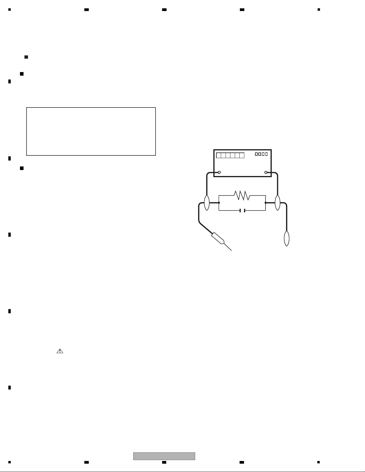
1. SERVICE PRECAUTIONS ....................................................................................................................................................5
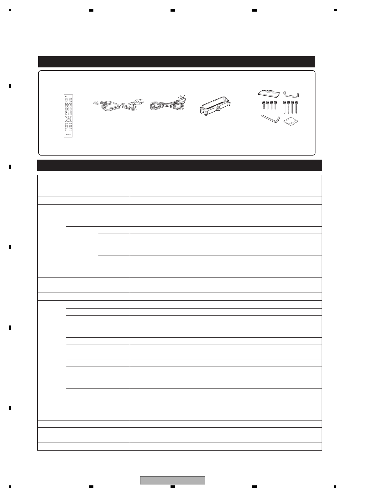
2. SPECIFICATIONS .................................................................................................................................................................6
2.1 SPECIFICATIONS...........................................................................................................................................................6
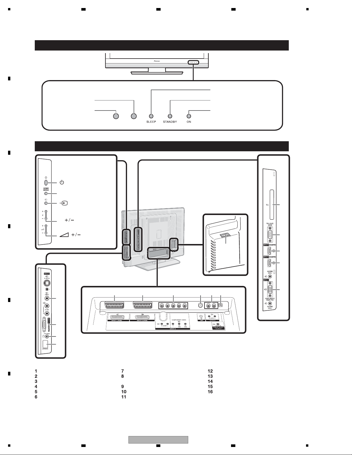
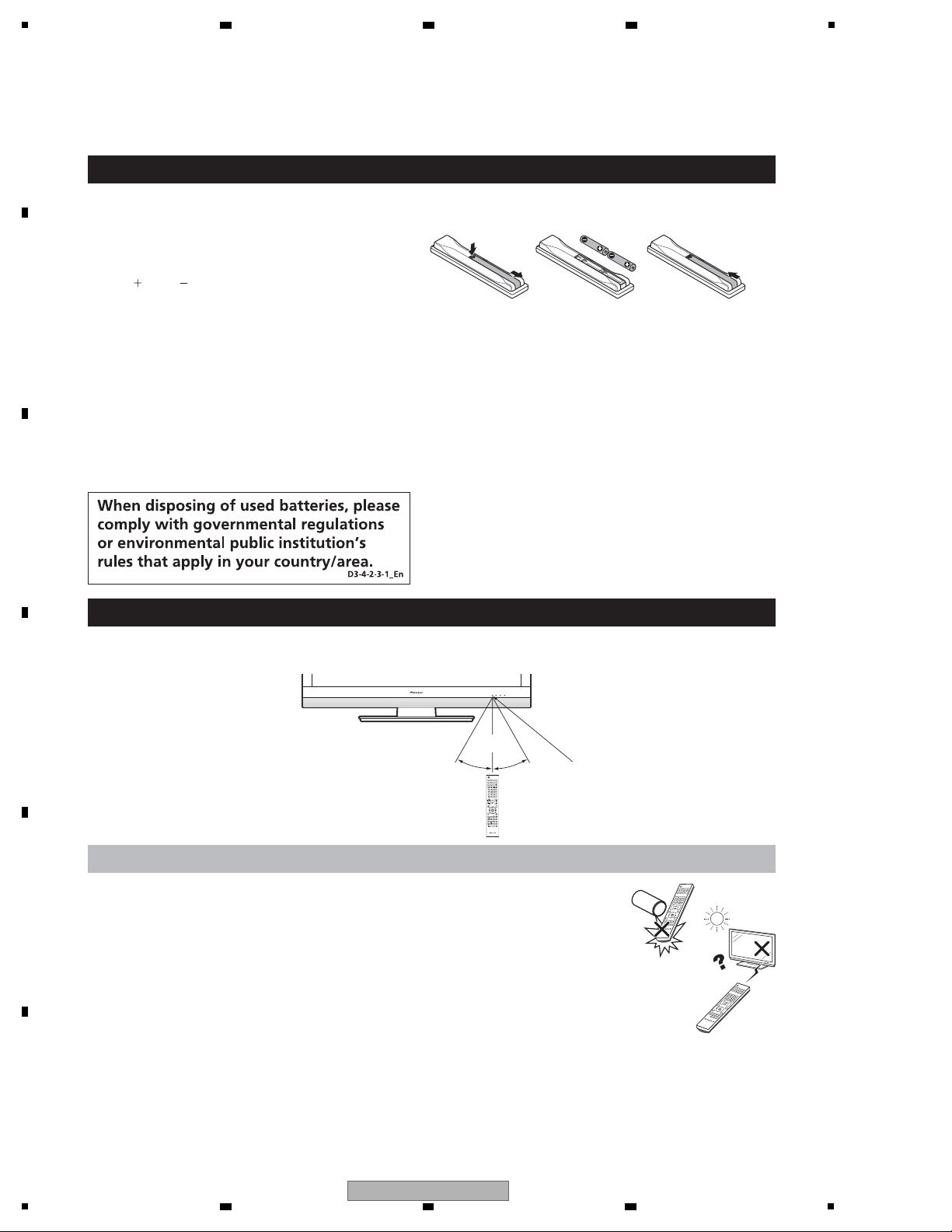
2.2 OPERATION MANUAL ...................................................................................................................................................7
2.3 DIMENSIONS ...............................................................................................................................................................12
3. REMOVING OF MAJOR PARTS .........................................................................................................................................13
4. ADJUSTMENT PROCEDURE.............................................................................................................................................25
5. TROUBLESHOOTING TABLE.............................................................................................................................................35
6. BLOCK DIAGRAM...............................................................................................................................................................58
6.1 WIRING DIAGRAM .......................................................................................................................................................58
6.2 SYSTEM BLOCK DIAGRAM ........................................................................................................................................60
6.3 TERMINAL BLOCK DIAGRAM .....................................................................................................................................66
6.4 MAIN BLOCK DIAGRAM ..............................................................................................................................................70
6.5 POWER BLOCK DIAGRAM..........................................................................................................................................72
7. SCHEMATIC DIAGRAM ......................................................................................................................................................75
7.1 DESCRIPTION OF SCHEMATIC DIAGRAM ................................................................................................................75
7.2 MAIN UNIT-1 .................................................................................................................................................................76
7.3 MAIN UNIT-2 .................................................................................................................................................................78
7.4 MAIN UNIT-3 .................................................................................................................................................................80
7.5 MAIN UNIT-4 .................................................................................................................................................................82
7.6 MAIN UNIT-5 .................................................................................................................................................................84
7.7 MAIN UNIT-6 .................................................................................................................................................................86
7.8 MAIN UNIT-7 .................................................................................................................................................................88
7.9 MAIN UNIT-8 .................................................................................................................................................................90
7.10 MAIN UNIT-9 ...............................................................................................................................................................92
7.11 MAIN UNIT-10 .............................................................................................................................................................94
7.12 MAIN UNIT-11 .............................................................................................................................................................96
7.13 MAIN UNIT-12 .............................................................................................................................................................98
7.14 MAIN UNIT-13 ...........................................................................................................................................................100
7.15 MAIN UNIT-14 ...........................................................................................................................................................102
7.16 MAIN UNIT-15 ...........................................................................................................................................................104
7.17 TERMINAL UNIT-1....................................................................................................................................................106
7.18 TERMINAL UNIT-2....................................................................................................................................................108
7.19 TERMINAL UNIT-3....................................................................................................................................................110
7.20 TERMINAL UNIT-4....................................................................................................................................................112
7.21 TERMINAL UNIT-5....................................................................................................................................................114
7.22 R/C, LED UNIT..........................................................................................................................................................116
7.23 KEY UNIT .................................................................................................................................................................118
7.24 MINI AV UNIT............................................................................................................................................................120
7.25 POWER UNIT ...........................................................................................................................................................122
7.26 AC INLET UNIT.........................................................................................................................................................124
8. PCB CONNECTION DIAGRAM ........................................................................................................................................126
8.1 MAIN UNIT..................................................................................................................................................................126
8.2 TERMINAL UNIT ........................................................................................................................................................134
8.3 R/C, LED UNIT............................................................................................................................................................138
8.4 KEY UNIT ...................................................................................................................................................................139
8.5 MINI AV UNIT..............................................................................................................................................................140
8.6 POWER UNIT .............................................................................................................................................................144
8.7 AC INLET UNIT...........................................................................................................................................................148
9. EXPLODED VIEWS AND PARTS LIST.............................................................................................................................150
9.1 PACKING SECTION ...................................................................................................................................................150
9.2 EXTERIOR SECTION.................................................................................................................................................152
9.3 LCD MODULE Assembly ............................................................................................................................................154

5
KRL-46V
56 7 8
56 7 8
A
B
C
D
E
F
1. SERVICE PRECAUTIONS
Precautions for using lead-free solder
Employing lead-free solder
• “PWBs” of this model employs lead-free solder. The LF symbol indicates lead-free solder, and is attached on the PWBs and service manuals. The
alphabetical character following LF shows the type of lead-free solder.
Example:
Using lead-free wire solder
• When fixing the PWB soldered with the lead-free solder, apply lead-free wire solder. Repairing with conventional lead wire solder may cause dam-
age or accident due to cracks.
As the melting point of lead-free solder (Sn-Ag-Cu) is higher than the lead wire solder by 40 °C, we recommend you to use a dedicated soldering
bit, if you are not familiar with how to obtain lead-free wire solder or soldering bit, contact our service station or service branch in your area.
Soldering
• As the melting point of lead-free solder (Sn-Ag-Cu) is about 220 °C which is higher than the conventional lead solder by 40 °C, and as it has poor
solder wettability, you may be apt to keep the soldering bit in contact with the PWB for extended period of time. However, Since the land may be
peeled off or the maximum heat-resistance temperature of parts may be exceeded, remove the bit from the PWB as soon as you confirm the
steady soldering condition.
Lead-free solder contains more tin, and the end of the soldering bit may be easily corroded. Make sure to turn on and off the power of the bit as
required.
If a different type of solder stays on the tip of the soldering bit, it is alloyed with lead-free solder. Clean the bit after every use of it.
When the tip of the soldering bit is blackened during use, file it with steel wool or fine sandpaper.
• Be careful when replacing parts with polarity indication on the PWB silk.
Lead-free wire solder for servicing
LFa
Indicates lead-free solder of tin, silver and copper.
LF a/a
Indicates lead-free solder of tin, silver and copper.
edoCnoitpircseD.oNtraP
ZHNDAi123250E J φ0.3mm 250g (1roll) BL
ZHNDAi126500E J φ0.6mm 500g (1roll) BK
ZHNDAi12801KE J φ1.0mm 1kg (1roll) BM
“PWB”: Printed Wiring Board

6KRL-46V
12 3 4
A
B
C
D
E
F
12 3 4
2. SPECIFICATIONS
2.1 SPECIFICATIONS
Specifications
Item 46″Flat screenTV,
Model: KRL-46V
LCD panel 46″Advanced Super View & BLACK TFT LCD
Resolution 2 073 600 pixels (1 920 ×1 080)
Video Colour System PAL/SECAM/NTSC 3.58/NTSC 4.43/PAL 60
TV Function TV-Standard Analogue CCIR (B/G, D/K, I, L/L’)
Digital DVB-T (OFDM)
Receiving
Channel
VHF/UHF E2–E12 ch (VHF), E21–E69 ch (UHF), F2–F10 ch, I21–I69 ch, IR A–IR J ch (Digital: E5–E69 ch)
CATV Hyper-band, S1–S41 ch
TV-Tuning System Auto Preset 999 ch: non-Nordic / 9999 ch: Nordic (ATV: 99 ch), Auto Label, Auto Sort
Audio Analogue NICAM/A2
Digital MPEG AUDIO
Brightness 450 cd/m2
Backlight life 60 000 hours (when “Backlight” is set to the default position)
Viewing angles H: 176°, V: 176°
Audio Power 15 W ×2
Speaker (100 mm × 40 mm) ×4
Terminals ANT UHF/VHF 75 ΩDin type (Analogue & Digital)
RS-232C D-Sub 9 pin male connector
INPUT1 SCART (AV input, Y/C input, RGB input, TV output)
INPUT2 SCART (AV input/monitor output, Y/C input, AV Link, RGB input)
INPUT3 S-VIDEO (Y/C input), RCA pin (AV input)
INPUT4 HDMI
INPUT5 HDMI
INPUT6 HDMI, Ø 3.5 mm jack
INPUT7 15 pin mini D-sub, Ø 3.5 mm jack
INPUT8 COMPONENT IN: Y/PB(CB)/PR(CR), RCA pin (AUDIO R/L)
DIGITAL AUDIO OUTPUT Optical SPDIF Digital audio output
C. I. (Common Interface) EN50221, R206001
OUTPUT RCA pin (AUDIO R/L)
Headphones Ø 3.5 mm jack (Audio output)
OSD language Czech, Danish, Dutch, English, Estonian, Finnish, French, German, Greek, Hungarian, Italian,
Latvian, Lithuanian, Norwegian, Polish, Portuguese, Russian, Slovak, Slovene, Spanish,
Swedish, Turkish
Power Requirement AC 220–240 V, 50 Hz
Power Consumption 253 W (0.5 W Standby) (Method IEC60107)
Weight 25.5 kg (Without stand), 30.5 kg (With stand)
Operating temperature 0 °C to + 40 °C
As a part of our policy of continuous improvement, Pioneer reserves the right to make design and specification
changes for product improvement without prior notice. The performance specification figures indicated are
nominal values of production units. There may be some deviations from these values in individual units.
•
Supplied accessories
Remote control unit
(×1)
AC cord (×2) Stand unit (×1)Cable clamp (×1)
Operation manual
Warranty card
•
•
•“AA” size alkaline battery (×2)
SOURCE
TV
STBDVR VCR
DVD
SELECT
HOME
MENU
MENU
RETURN
EXIT
DVDTOPMENU/
GUIDE
EPG
P
456
789
0P.INFO
123
INFO
CHRETURN
TV
CTRL
HDMI RECSTOP
HDD
AV
SELECTION
CMSKIP
DVD
TOOLS
SCREEN
SIZE
DTV
RADIO
1234
5678
TV
INPUT
ENTER
(RRMCGA687WJSA)
(QACCKA021WJPZ)
(TINS-D818WJZZ)
(QACCBA073WJPZ)
(LHLDWA173WJKZ) (CDAI-A376WJ04)

7
KRL-46V
56 7 8
56 7 8
A
B
C
D
E
F
2.2 OPERATION MANUAL
TV DTV
RADIO
1234
5678
TV
INPUT
456
789
123
0P.INFO
INFO
P
CH RETURN
EXIT
DVD TOPMENU/
GUIDE
EPG
ENTER
HOME
MENU
MENU
RETURN
CTRL
HDMI REC STOP
HDD
AV
SELECTION
CM SKIP
DVD
TOOLS
SCREEN
SIZE
SOURCE
TV
STB DVR VCR
DVD
SELECT
1
2
3
4
12
5
7
9
11
13
10
6
8
14
19
20
15
17
18
21
22
16
(TV) (Standby/On)
INPUT1–8
Select an input source.
Buttons for mode switch
TV
Press to access conventional
analogue TV mode.
DTV
Press to access digital TV mode.
RADIO
DTV: Switch between Radio and
Data mode.
When only data broadcasting (no
radio broadcasting) is transmitted
by DVB, the radio broadcasting
will be skipped.
0–9 numeric buttons
Set the channel.
Enter desired numbers.
Set the page in teletext mode.
When the five Nordic countries
(Sweden, Norway, Finland,
Denmark, or Iceland) are selected
in the country setting from “Auto
Installation”, DTV
services are four digits. When
another country is selected, DTV
services are three digits.
(INFO)
Press to display the station
information (channel number, signal,
etc.) in the upper right corner of the
screen.
CH RETURN
Press to return to the previously
selected channel or external input.
P
Select the TV channel.
Select the page in teletext mode.
(Mute)
TV sound on/off.
(EXIT)
Exit the “HOME MENU” screen.
(Cursor)
Select a desired item on the setting
screen.
ENTER
Execute a command within the
“HOME MENU” screen.
ATV/DTV: Display the programme
list when no other “HOME MENU”
screen is running.
(HOME MENU)
“HOME MENU” screen on/off.
1
2
3
•
4
•
5
6
7
8
9
10
11
Buttons for useful operations
(Subpage)
(Subtitle)
Switch subtitle languages on/off
(Reveal hidden Teletext)
(Freeze/Hold)
Press to freeze a moving image on
the screen.
Teletext: Stop updating teletext
pages automatically or release the
hold mode.
(Teletext)
ATV: Display analogue teletext.
DTV: Select MHEG-5 and teletext for
DTV.
P.INFO
Press to display programme
information which is transmitted
through digital video broadcasting in
the upper left corner of the screen
(DTV only).
(Volume)
Increase/decrease TV volume.
EPG
DTV: Display the EPG screen.
(RETURN)
Return to the previous “HOME
MENU” screen.
Buttons for HDMI CONTROL
If external equipment is connected
via HDMI cables and is HDMI
CONTROL compatible, you can use
these HDMI CONTROL buttons.
Buttons for picture adjustments
SCREEN SIZE
Select a screen size.
AV SELECTION
Select a video setting.
SELECT
Switch the selection among TV,
STB,DVD/DVR, and VCR, so that
you can control other connected
equipment, using the supplied
remote control unit.
(Sound mode)
Select a sound multiplex mode.
14
15
16
17
18
19
20
21
22
Remote control unit
Colour (Red/Green/Yellow/Blue)
buttons
The coloured buttons are
correspondingly used to select the
coloured items on the screen (e.g.
EPG, MHEG-5, Teletext).
(SOURCE)
12
13
NOTE
Press and hold both 9and 18 on the remote control unit to show “100Hz” demonstration in a dual screen.•
()

8KRL-46V
12 3 4
A
B
C
D
E
F
12 3 4
AC INPUT terminal
INPUT3 terminals
INPUT4 (HDMI) terminal
PHONES (Headphones)
SERVICE socket
INPUT1 (RGB) terminal
TV (Front view)
TV (Rear view)
INPUT2 (RGB) terminal
INPUT8 (COMPONENT/AUDIO)
terminal
ANT (aerial) terminal
OUTPUT (AUDIO) terminals
DIGITAL AUDIO OUTPUT terminal
COMMON INTERFACE slot
RS-232C terminal
INPUT5 (HDMI) terminal
INPUT6 (HDMI/AUDIO) terminals
INPUT7 (ANALOGUE RGB/AUDIO)
terminals
RLS*
RLS = Room Light Sensor*
2
3
4
67891011
1
5
12
13
16
15
14
HOMEMENU button
(Power) button
Volume buttons
P( ) Programme
( )
[channel] buttons
(INPUT SOURCE)
button
WARNING:
Excessive sound pressure from
earphones and headphones can cause
hearing loss.
Remote control
sensor
ON indicator
SLEEP indicator
STANDBY indicator

9
KRL-46V
56 7 8
56 7 8
A
B
C
D
E
F
Confirm that there are eight screws (four short
screws and four long screws) with the stand
unit.
Attach the supporting post for the stand unit
onto the base using the four long screws with
the hex key (supplied) as shown.
1
2
3
NOTE
To detach the stand unit, perform the steps in reverse
order.
•
Attaching the stand unit
Before attaching (or detaching) the stand, unplug the AC cord from the AC INPUT terminal.
Before performing work, spread cushioning over the surface on which you will be laying the TV. This will prevent
it from being damaged.
CAUTION
Attach the stand in the correct direction.
Be sure to follow the instructions. Incorrect installation of the stand may result in the TV falling over.
•
•
•
•
Hex key
Long
screw
Short
screw
Hex key
Soft
cushion
Insert the stand into the openings on the
bottom of the TV. (Hold the stand so it will
not drop from the edge of the base area.)
Insert and tighten the four short screws into
the four holes on the rear of the TV
1
2

10 KRL-46V
12 3 4
A
B
C
D
E
F
12 3 4
Inserting the batteries
Before using the TV for the first time, insert two supplied “AA” size alkaline batteries. When the batteries become
depleted and the remote control unit fails to operate, replace the batteries with new “AA” size batteries.
Open the battery cover.
Insert two supplied “AA” size alkaline batteries.
Place batteries with their terminals corresponding to the
( ) and ( ) indications in the battery compartment.
Close the battery cover.
CAUTION
Improper use of batteries can result in chemical leakage or explosion. Be sure to follow the instructions below.
Do not mix batteries of different types. Different types of batteries have different characteristics.
Do not mix old and new batteries. Mixing old and new batteries can shorten the life of new batteries or cause
chemical leakage in old batteries.
Remove batteries as soon as they have worn out. Chemicals that leak from batteries can cause a rash. If you
find any chemical leakage, wipe thoroughly with a cloth.
The batteries supplied with this product may have a shorter life expectancy due to storage conditions.
If you will not be using the remote control unit for an extended period of time, remove the batteries from it.
When replacing the batteries, use alkaline batteries instead of zinc-carbon ones.
1
2
•
3
•
•
•
•
•
•
Cautions regarding the remote control unit
Do not expose the remote control unit to shock. In addition, do not expose the
remote control unit to liquids, and do not place in an area with high humidity.
Do not install or place the remote control unit under direct sunlight. The heat may
cause deformation of the unit.
The remote control unit may not work properly if the remote control sensor of the
TV is under direct sunlight or strong lighting. In such cases, change the angle of the
lighting or the TV, or operate the remote control unit closer to the remote control
sensor.
•
•
•
SOURCE
TV
STBDVR VCR
DVD
SELECT
HOME
MENU
MENU
RETURN
EXIT
DVDTOPMENU/
GUIDE
EPG
P
456
789
0P.INFO
123
INFO
CHRETURN
TV
CTRL
HDMI RECSTOP
HDD
AV
SELECTION
CMSKIP
DVD
TOOLS
SCREEN
SIZE
DTV
RADIO
1234
5678
TV
INPUT
ENTER
30° 30°
Using the remote control unit
Use the remote control unit by pointing it towards the remote control sensor. Objects between the remote control
unit and sensor may prevent proper operation.
5 m
Remote control sensor

11
KRL-46V
56 7 8
56 7 8
A
B
C
D
E
F
Troubleshooting
Problem Possible Solution
No power.•Check if you pressed (TV) on the remote control unit.
If the indicator on the TV lights up red, press (TV).
Is the AC cord disconnected?
Check if you pressed on the TV.
•
•
•
The TV cannot be operated.• External influences such as lightning, static electricity, etc., may cause improper operation. In this
case, operate the TV after first turning off the power, or unplugging the AC cord and re-plugging
it in after one or two minutes.
•
Remote control unit does not operate.• Are batteries inserted with polarity ( , ) aligned?
Are batteries worn out? (Replace with new batteries.)
Are you using it under strong or fluorescent lighting?
Is a fluorescent light illuminating to the remote control sensor?
•
•
•
•
Picture is cut off.• Is the image position correct?
Are screen mode adjustments (SCREEN SIZE) such as picture size made correctly?
•
•
Strange colour, light colour, or dark
colour, or colour misalignment.
• Adjust the picture tone.
Is the room too bright? The picture may look dark in a room that is too bright.
Check the “Colour System” setting.
•
•
•
Power is suddenly turned off.• The TV’s internal temperature has increased.
Remove any objects blocking the vent or clean.
Is the “Sleep Timer” set? Select “Off” from the “Sleep Timer” menu.
Is “No Signal Off” or “Ecology” activated?
•
•
•
No picture.• Are connections to external equipment correct?
Is the input signal type selected correctly after connection?
Is the correct input source selected?
Is a non-compatible signal being input?
Is the picture adjustment correct?
Is the aerial connected properly?
Is “On” selected in “Audio Only”?
•
•
•
•
•
•
•
No sound.• Is the volume too low?
Make sure that headphones are not connected.
Check if you pressed on the remote control unit.
•
•
•
The TV sometimes makes a cracking
sound.
• This is not a malfunction. This happens when the cabinet slightly expands and contracts
according to changes in temperature. This does not affect the TV’s performance.
•
Cautions regarding use in high and low temperature environments
When the TV is used in a low temperature space (e.g. room, office), the picture may leave trails or appear slightly delayed.
This is not a malfunction, and the TV will recover when the temperature returns to normal.
Do not leave the TV in a hot or cold location. Also, do not leave the TV in a location exposed to direct sunlight or near a
heater, as this may cause the cabinet to deform and the LCD panel to malfunction.
Storage temperature: 5 °C to 35 °C.
•
•
Information on the software license for this product
Software composition
The software included in this product is comprised of various software components whose individual copyrights are held by
Pioneer or by third parties.
Software developed by Pioneer and open source software
The copyrights for the software components and various relevant documents included with this product that were developed
or written by Pioneer are owned by Pioneer and are protected by the Copyright Act, international treaties, and other relevant
laws. This product also makes use of freely distributed software and software components whose copyrights are held by
third parties. These include software components covered by a GNU General Public License (hereafter GPL), a GNU Lesser
General Public License (hereafter LGPL) or other license agreement.
Obtaining source code
Some of the open source software licensors require the distributor to provide the source code with the executable software
components. GPL and LGPL include similar requirements. For information on obtaining the source code for the open source
software and for obtaining the GPL, LGPL, and other license agreement information, contact your local Pioneer Customer Service.
We are unable to answer any questions about the source code for the open source software. The source code for the
software components whose copyrights are held by Pioneer is not distributed.
Acknowledgements
The following open source software components are included in this product:
• linux kernel • modutils • glibc • zlib • libpng

12 KRL-46V
12 3 4
A
B
C
D
E
F
12 3 4
2.3 DIMENSIONS
550
1101
400
400
175
(1023.4)
(1023,4)
761
63 698
(575.6)
(575,6)
(122.5)
(122,5)
96
453
325

13
KRL-46V
56 7 8
56 7 8
A
B
C
D
E
F
3. REMOVING OF MAJOR PARTS
1. Remove the 2 lock screws , 6 lock screws and the 8 lock screws . Detach the Rear Cabinet.
123
REAR CABNET
3
2 1

14 KRL-46V
12 3 4
A
B
C
D
E
F
12 3 4
2. Remove all the connectors from PWBs.
3. Remove the 2 lock screws . and detach the Speaker L/R.
Wire "SP"
Wire "SP"
Wire "SP" to WH
Wire "SP" to WH
Wire "SP" to PIN
4
LrekaepSRrekaepS
4

15
KRL-46V
56 7 8
56 7 8
A
B
C
D
E
F
4. Remove all the connectors from PWBs.
5. Remove the R/C, LED Unit.
R/C, LED PWB
Wire "RA"
from OBON
Wire
R/C, LED PWB Front side
LED PWB Back side
(3-3)Pull out Wire "IL","RA" from bottom
(3-1) Set R/C, LED PWB Under LIB
R/C, LED PWB
(with wire)
(3-2) Push PWB hooked
#Set PWB to gide lib surely
Wire "RA" to WH

16 KRL-46V
12 3 4
A
B
C
D
E
F
12 3 4
6. Remove the 8 lock screws , and the 6 lock hooks . Detach the LCD Panel Module.
56
5
FRONT CABINET
6
LCD PANEL MODULE
LCD PANEL MODULE

17
KRL-46V
56 7 8
56 7 8
A
B
C
D
E
F
7. Remove the 2 lock screws . and detach the Bottom Cover.
7
BOTTOM COVER
FRONT CABINET
7
8. blank

18 KRL-46V
12 3 4
A
B
C
D
E
F
12 3 4
10.Remove the 4 lock screws . and detach the CTL SHIELD with RADIATOR.
11.Remove all the connectors from PWBs.
8
CTL-SHIELD with RADIATOR
8
Wire "LC" to WH
Wire "KM", "VD", "US" to WH
FFC "HM" to WH
Wire "KM" to Hook
Wire "KM" to WH
Wire "LC", "LA2", "LB" to WH
Wire "LW", "PL" to WH
Wire "LC", "LA1" to WH
Wire "LA1"
Wire "LA2"
Wire "LB"
FFC "HM"
Wire "US"
Wire "VD"
Wire "KM"
Wire "LP"
Wire "LW"
9. blank

19
KRL-46V
56 7 8
56 7 8
A
B
C
D
E
F
12.Remove the 1 lock screw , and the 12 lock screws . Detach the Chassis Tray and MINI AV SUB ASSY.
13.Remove the 14 lock screws . and detach the Panel Support Angle.
910
10
Wire "LC"
MINI AV SUB ASSY
CHASSIS TRAY
9
11
PNL SUPPORT ANG
LCD MODULE
Wire "LC"
11

20 KRL-46V
12 3 4
A
B
C
D
E
F
12 3 4
14.Remove the 6 lock hooks . and detach the KEY Unit.
15.Remove the 2 lock screws , and the 2 lock screws . Detach the MINI AV Unit.
12
13 14
M-AV KEY COV
KEY PWB
MINI AV PWB
MINI AV ANG
Slant View
Top View
#Set PWB under LIB
13
14
12
MINI AV PWB MINI-AV SHIELD
Table of contents
Other Pioneer TV manuals

Pioneer
Pioneer PDP-614MX Use and care manual

Pioneer
Pioneer PDP-503MXE User manual

Pioneer
Pioneer PDK-WM02 User manual

Pioneer
Pioneer VSX-917V-S User manual

Pioneer
Pioneer KURO KRP-500A User manual

Pioneer
Pioneer Kuro PDP-LX5090 User manual

Pioneer
Pioneer PDP-SX5080D User manual

Pioneer
Pioneer Digital TV User manual

Pioneer
Pioneer S-LX70-C User manual

Pioneer
Pioneer PDP-LX5080D User manual