1
En
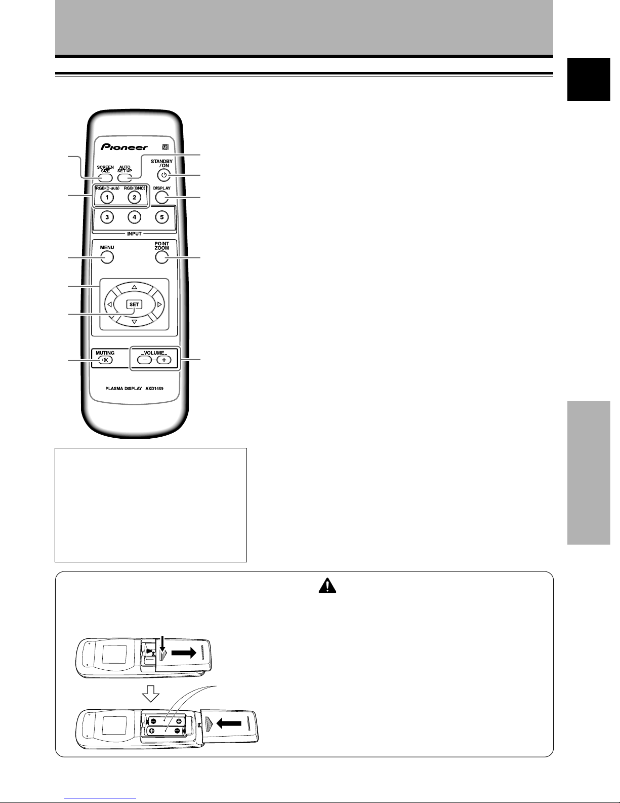
Part Names and Functions English
Features Contents
Before Proceeding
Introduces newly developed 50" XGA Wide Plasma Panel
The new high-precision XGA 50" wide plasma panel pushes the
envelope of previous high-luminance panels, producing brighter,
clearer images with higher contrast.
¶Newly developed full screen filter produces clear,
high-contrast images even in a lighted room.
The new full screen filter suppresses surface reflections to a
minimum, producing clear, high-contrast images even in lighted
locations. Unnecessary frequency components of RGB signals
are also cut, greatly enhancing color reproduction.
¶Supports wide range of computer signal formats
Direct display of computer signals is supported in resolutions
from 640x400 and 640x480 (VGA) to 1024x768 (XGA) and
1280x768; computer signals with resolutions of 1280x1024
(SXGA) and 1600x1200 (UXGA) are supported in compressed
display format. Screen aspect ratios include DOT-BY-DOT, 4:3,
FULL, and PARTIAL*1
* 1. Operation of screen aspect ratios and screen size differ
depending on the input signal.
¶Free Installation Configuration
Broader installation possibilities with thinner,
lighter, high-endurance design.
While producing a large 50" screen image, the display is only
98mm thick, and weighs in at only 38.9 kg. On the other hand,
the efficient heat-radiating design greatly improves
environmental operating conditions. The thinner, lighter design,
coupled to high-endurance construction greatly broadens the
range of possible installation locations and styles.
¶High reliability for commercial applications
This display is provided with features giving it high dependability
in commercial applications, including the ability to suppress peak
luminance in accordance with the viewing program, and to
change the cooling fan’s speed in accordance with changes in
operating environment. Such features provide safety and high-
endurance under conditions of commercial use.
¶Improved usability
User convenience has been improved by the inclusion of
features making the display even more compatible with your
computer. Some of these include the one-touch screen
adjustment AUTO SETUP function for computer connections,
and the POINT ZOOM function to enlarge local portions of the
screen image to display important detailed program data.
¶Power-Saving Design
This display achieves the lowest power consumption in the
industry for screens in the 50" XGA class (380 W / about 20%
reduced according to in-house comparison of previous products).
Further, use of the power-control function provides a 20%
reduction in power consumption compared to normal operating
conditions (MODE 1, with color-bar signal input).
¶Optional line (sold separately)
(For details, please consult the dealer where this unit was
purchased.)
1 Table top stand: PDP-503MXE display stand.
2 Wall installation unit: Wall installation bracket designed as a
wall interface for securing the unit.
3
Speaker system designed specifically for plasma displays
(width: 7.4 cm): With the adoption of a vertical 2-way system
designed with a 2.5 cm domed conical tweeter and
newly developed 4.5 cm wide oval shaped units
arranged vertically. (When speakers are attached,
the operation panel on this unit is not operable.)
4 Video card: Expansion card allows viewing of video signals
and computer digital RGB signals (DVI compliant).
5 Cable cover: Dedicated cover to allow fashionable concealment
of rear cable connections.
Safety Precautions ................................... i
Before Proceeding ................................... 2
How to Use This Manual ............................................... 2
Checking Supplied Accessories .................................... 3
Part Names and Functions ..................... 4
Main Unit ........................................................................ 4
Remote Control Unit ...................................................... 5
Connection Panel ........................................................... 6
Installation and Connections ................. 8
Installation of the Unit ................................................... 8
Connection to INPUT1 and INPUT2 ............................ 10
Audio Connections ....................................................... 12
Control Cord Connection ............................................. 13
Power Cord Connection ............................................... 13
How to Route Cables.................................................... 14
Setting Up the System ......................... 15
Setup after Connection ................................................ 15
Operations ............................................. 17
Selecting an Input Source ........................................... 17
Screen Size Selection................................................... 19
Partial Image Enlargement (POINT ZOOM) ............... 20
Automatic Power OFF .................................................. 21
Display Panel Adjustments .................. 22
Adjusting the Picture Quality ...................................... 22
Adjusting the Image Position and Clock
(Automatic Adjustment) .............................................. 23
Manual Adjustment of Screen Position and
Clock .............................................................................. 24
Other Operations .................................. 25
Rewriting the Input Display (INPUT LABEL) .............. 25
Power Control Function ............................................... 26
AUTO FUNCTION ......................................................... 26
Audio Output (AUDIO OUT) ........................................ 27
Additional Information ......................... 28
Cleaning ........................................................................ 28
Troubleshooting ........................................................... 28
Specifications ............................................................... 31
Supplement 1 ............................................................... 32
Supplement 2 ............................................................... 33
Explanation of Terms ................................................... 33