Pipehorn 450 Mag Horn User manual

Model 450 Mag Horn
Ferromagnetic Locator
User’s Manual
Manufactured Exclusively By:
Utility Tool Company, Inc.
29 Commerce Boulevard
Birmingham, Alabama 3521
2 5-956-371
“User’s Hotline” 800-952-3710

DANGER! SHOCK HAZARD
CONNECTING DIRECTLY TO ANY CON-
DUCTOR CAN BE HAZARDOUS AND RE-
SULT IN ELECTRIC SHOCK, INJURY, OR
DEATH. ONLY LICENSED OR AUTHO-
RIZED PERSONS SHOULD MAKE DIRECT
CONNECTIONS TO POTENTIALLY ENER-
GIZED CONDUCTORS.
This device complies with Part 15 of the FCC
Rules. Operation is subject to the following
two conditions: (1) this device may not cause
harmful interference, and (2) this device must
accept any interference received, including
interference that may cause undesired op-
eration.
NOTICE
This User’s Manual is provided as an infor-
mational guide only and is subject to change
without notice.
This Manual contains certain information
which is proprietary in nature and protected
by U.S. and Foreign Patents, Copyrights,
and Registered Trademarks. All rights are
reserved. No part of this document may be
photocopied, reproduced, transmitted, or
converted into another language without the
express written consent of Utility Tool Com-
pany, Inc.
Copyright © Utility Tool Company, Inc. 20042

ontents Page
Section 1: Frequently Asked Questions ------------- 4
Section 2: Manual and terminology ------------------- 4
Section 3: Operation ---------------------------------------
Power n/ ff
Setting and Using Sensitivity Control
Detecting the Magnetic Field
Section 4: Locating Techniques ----------------------- 7
Searching and Pin Pointing
Property Markers
Valve Box Covers
Cast Iron Pipe Joints
Manhole Covers
Septic Tanks and Well Casings
Metal Drums
Locating in Snow and Water
Searching Along a Fence or Building
Section : Maintenance ---------------------------------- 1
Battery Replacement
Warranty
Repair Service
Section 6: “User’s Hotline” ----------------------------- 19
3

1 Frequently Asked Questions
• What is the Model 450 Mag Horn?
It is a stand-alone locator specifically designed
to detect ferrous (iron) objects, such as property
pins, curb boxes, manhole and valve covers. It
is not necessary to o n a Pipehorn Pipe and
Cable Locator.
•What is it designed to do?
The Mag Horn is designed to locate concealed
ferrous (iron) object’s magnetic field. It responds
to the difference in magnetic field strength
detected by t o sensors in the locator. The tone
from the speaker changes in pitch to indicate
the presence of a ferrous object.
• What advantages does Mag Horn offer?
The Model 450 Mag Horn is extremely effective
hen locating small or deep ferrous objects
hile screening out nonferrous coins, aluminum
cans and similar interfering objects.
•It’s unique ergonomic design makes it easier to
use than other ferromagnetic locators. Location
of the Sensitivity Control also enables one-
handed operation.
2 Manual and Terminology
When the follo ing terms are used in this manual,
they have the meanings specified belo :
4

•bject - An object is the buried item you are
trying to locate, such as a manhole cover, valve
box lid, property stake, etc. It is required that the
object have iron (ferrous) content to be detected
by the Mag Horn.
• Field – the magnetic field surrounding the object
being detected
• Sensitivity – the strength of field the locator is
set to detect; increasing the sensitivity allo s the
locator to detect smaller or deeper objects
• Searching Signal - the lo est setting on the Mag
Horn that ill allo you to locate your target. This
setting ill depend upon several factors such as
size, depth and orientation of object, and interfer-
ence of other objects that may be around the
target.
• Peak Signal - The point here the magnetic field
is the strongest. Usually this is directly over the
object
3 Operation - This section covers: Turning on your
Mag Horn, Setting and Using the Sensitivity Control,
Detecting the Magnetic Field and Searching and Locating
3.1 Power On/Off
5

The po er On/Off and SensitivitySettings are
controlled by rotating the knob located on the
side of the Mag Horn. The unit has been
shipped ith the Sensitivity Knob in the “off”
position or turned fully counter-clock ise. To
turn on, rotate the knob clock ise until you feel
it click. The Mag Horn ill emit a very high
pitch tone and then settle to a lo er tone of
about 40 kHz. Turn the Mag Horn off by rotating
the knob to its full counter-clock ise position.
You ill feel it click and all sound ill be lost.
3.2 Setting and Using the Sensitivity Control
Note: Use only the minimum
sensitivity needed to get the job done.
This ill make your locates easier and faster.
Low Sensitivity is used to reduce signal
interference from nearby magnetic objects.
This is achieved by rotating the Sensitivity
Control Knob counter-clock ise. Reduced
Sensitivity is also useful to locate and pin-point
strongly magnetic markers.
At minimum sensitivity, you should be able to
hold or rotate the Mag Horn to any position
ithout producing a significant change in tone.
This ill occur only hen you are not over or
near a ferrous object.
High Sensitivity is useful to locate smaller or
deeper buried objects. Increase sensitivity by
rotating the Sensitivity Control knob clock ise.
Increasing sensitivity may also increase
6

interference from smaller objects in the ground.
When Sensitivity is set in the high range you ill
experience tone changes based on the locators
position in the earth’s magnetic field. Moving or
rotating the Mag Horn ill generate changes in
the tone.
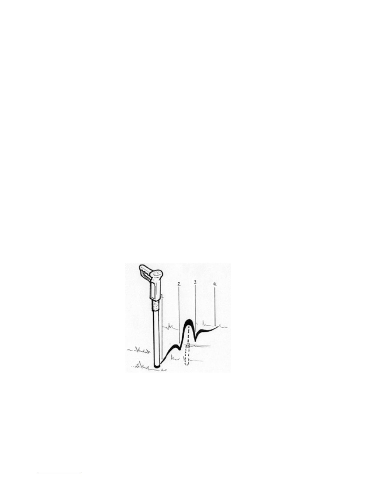
3.3 Detecting the Magnetic Field
As you can see from the dra ing above, the Mag
Horn has t o sensors used to detect the mag-
netic field of ferrous objects. When sensor 1 is
closer to the object than sensor t o, Mag
Horn’s pitch ill become higher or more shrill,
indicating that it has detected a ferrous object.
Experiment ith an object above ground or in a
kno n location to become familiar ith the Mag
Horn’s sounds and responses.
4 Locating Techniques
4.1 Searching and Pin-Pointing
Keep your sensitivity set in the lo er range.
This ill be your searching signal. This helps 7
eliminate un anted signals from interfering objects.
Lo er the tip of the Mag Horn near the surface of the
ground and begin a slo s eep from left to right. Based
on the depth and position of the object, more sensitivity
may be required. It is up to the locator to make this
determination and properly set the sensitivity.
As you near a ferrous object the tone of the Mag Horn
ill respond by increasing its pitch, becoming more
shrill. This is an indication that you are near a ferrous
object.
When you are above the target, s eep in an “X” pattern
as sho n above. As you s eep, note here the signal
peaks or is most shrill. Adjust your “X” pattern s eep
until the peak from each s eep direction occurs in the
same spot. This ill help you to find the center of the
target object.
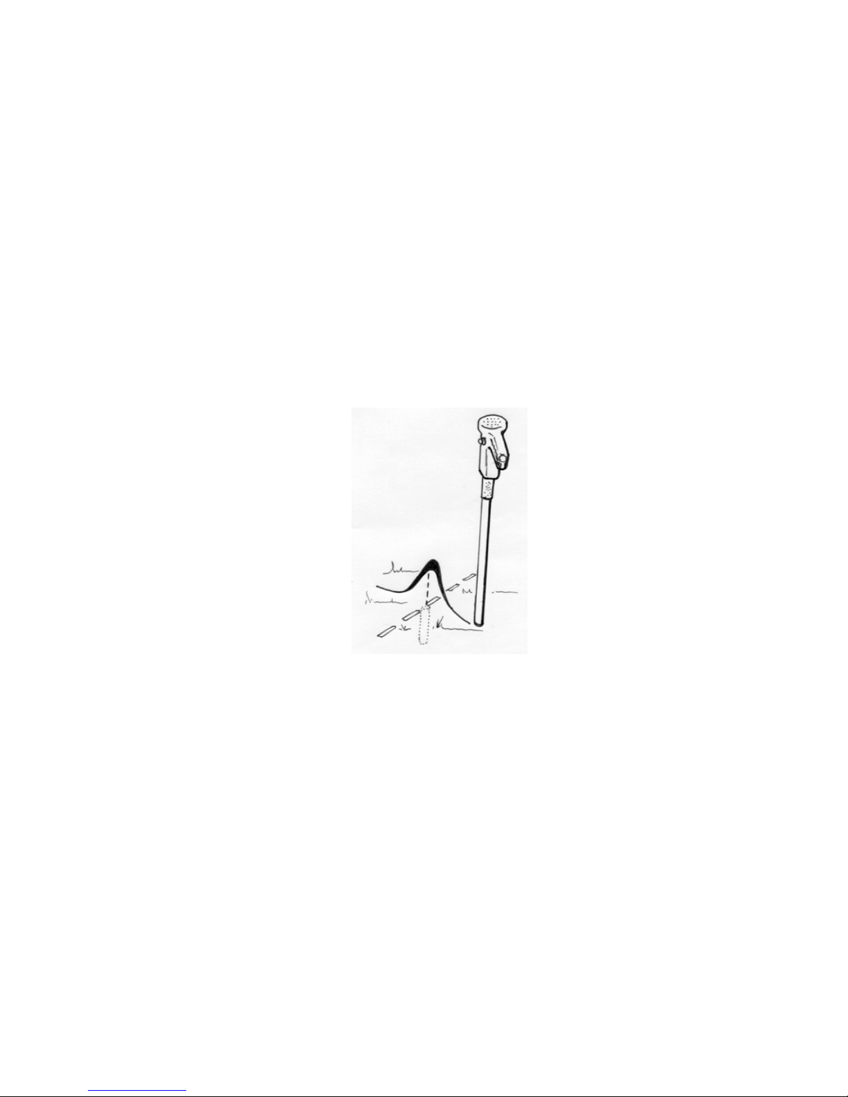
On vertical objects, such as property pins, the peak
signal ill occur directly over the center of the pin. On
horizontal objects, like manhole covers, the peak signal
ill occur at each edge. See the section for Locating
Property Markers (Section 4.2) and Man Hole Covers
(Section 4.5) for more detail.
8
4.2 Locating Property Markers
When locating property markers, the peak
signal ill occur hen the Mag Horn is directly
over the marker or pin. This is assuming the
marker is in a vertical or near vertical position. If
the marker is lying in a horizontal position you
ill receive t o peak signals, one at each end of
the marker.
After you have located the marker, use the “X”
pattern described earlier in the manual to better
pinpoint the center of the marker.
The magnetic field in highly magnetized mark-
ers can provide three peak signals. T o eak
signals to each side and a stronger signal
directly over the pin. Care should be taken to
make sure you have s ept all the ay across
the pin to locate the strongest signal.
Turning your sensitivity do n as you start to
detect the marker ill help you eliminate eaker
signals.
9

4.3 Valve Boxes and overs
Valve Boxes and/or Covers made of ferrous
materials can provide excellent signal response.
Based on the size of the Valve Box you may experi-
ence a ider signal peak than ith smaller objects like
a property pin.
Plastic valve boxes may have a strong magnet inside
to make them easy to locate. In this situation you
should use caution because the magnet ill produce
eak signals to each side of the box and a stronger
peak signal over the center of the box. (See Sketch in
Section 4.2) Turning the sensitivity do n as you begin
to detect the magnetic marker ill help you eliminate
the un anted signals.
You can trace the outline of the cover by reducing the
sensitivity control to the lo est setting that ill detect
the cover. As you s eep 360o around the cover, the
signal ill peak each time you pass over the outer rim
of the cover. Mark each of these peak signals to detail
the cover dimensions.
10
4.4 ast Iron Pipe Joints
Locating the pipe first ill make joint location
easier and faster. Because of its high metal
content, cast iron pipe can be located ith a
Mag Horn but it is more efficient to use a
Pipehorn Pipe and Cable Locator to trace and
mark out the pipe location.
Set the Mag Horn sensitivity to maximum, fully
clock ise, and position the Mag Horn probe
tip approximately 1 foot above the ground over
the pipeline you have marked.
Do not sweep, turn or tilt the Mag Horn.
Keep it upright and positioned over the pipeline
marks as you alk the line.
Mark the point(s) here you experience peak
signals. Peak signals should occur at equal
distance, such as 20’ 0” for 20’ 0” sections of
pipe.
When you finish alking the line, go back and
check the marks you have made. Reduce
11

sensitivity and begin searching the area as de-
scribed in the search and s eep section of this
manual.
Generally the larger the pipe the deeper it can be
located. 4” diameter cast iron pipe joints can be
located at depths up to 10 feet assuming there is
no significant interference from foreign objects.
In pipelines that run east and est, you may find
that the location of the joints can be slightly off from
the point here you detect the peak signal.
4.5 Manhole covers
A strong magnetic field is produced by the support
collar that supports manhole lids. This is hat you
ill detect ith the Mag Horn. Your peak signals ill
occur at the outer edges of the cover.
By reducing outer sensitivity setting you can easily
locate and trace the edges of manhole covers and
reduce the amount of ork required to uncover the
lid.
12

4.6 Septic Tanks and Well asings
Septic Tanks can be found by locating the iron
handle and/or the rebar used to reinforce the
tank.
Well Casings are long and produce a strong
magnetic field making them easy to locate.
Signal response ill be very much like that of a
manhole cover. Strong at the outer edges ith
possibly t o peaks as you s eep across the
casing.
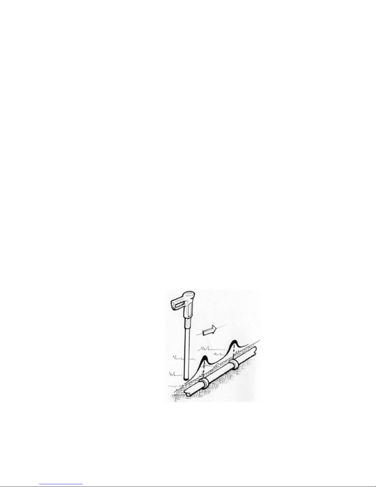
4.7 Metal Drums
Metal drums made ith ferrous material can be
located ith your Mag Horn. Signal output ill
vary based on the drum’s position in the earth
and its depth. (See sketch on next page)
13

Laying on its side the drum will present two
wea er and more seperated pea s while in an
upright position the pea s will be closer together
and possibly stronger. Most drums can be lo-
cated up to 8 feet in depth.
4.8 Locating in Snow and Water
The probe on your MagHorn has been sealed to
prevent water entry. You can insert the probe in
water and snow up to 1’0” without harm. How-
ever, the electronic components located in the
cast body must be ept dry.
4.9 Searching along a metal building or fence
This type of search requires a different technique
from all other methods described in this manual.
Near the fence or building where the target object
is suspected to be, position the Mag Horn as
shown in the s etch below. This position is used
to eep Sensor 2 away from the fence or build-
ing.
14

15
Set the sensitivity to its maximum, fully clock-
ise.
S eep the Mag Horn left and right as you slo ly
move for ard in a line along the fence or building.
Moving for ard in small increments ill prevent
passing over the target.
When you are over a ferrous object the signal
output ill drop dramatically.
When this happens the object has been located
at approximately 1 ½” from the end of the probe.
Moving the probe even slightly from this position
ill create an immediate increase in signal.
5 Maintenance
The Mag Horn does not require routine mainteance
other than keeping fresh, charged batteries installed.
based on the battery manufacturer’s requirements
to prevent corrosion in the battery chamber.
16
Batteries should be replaced periodically based
on the battery manufacturer’s requirements to
prevent corrosion in the battery chamber.
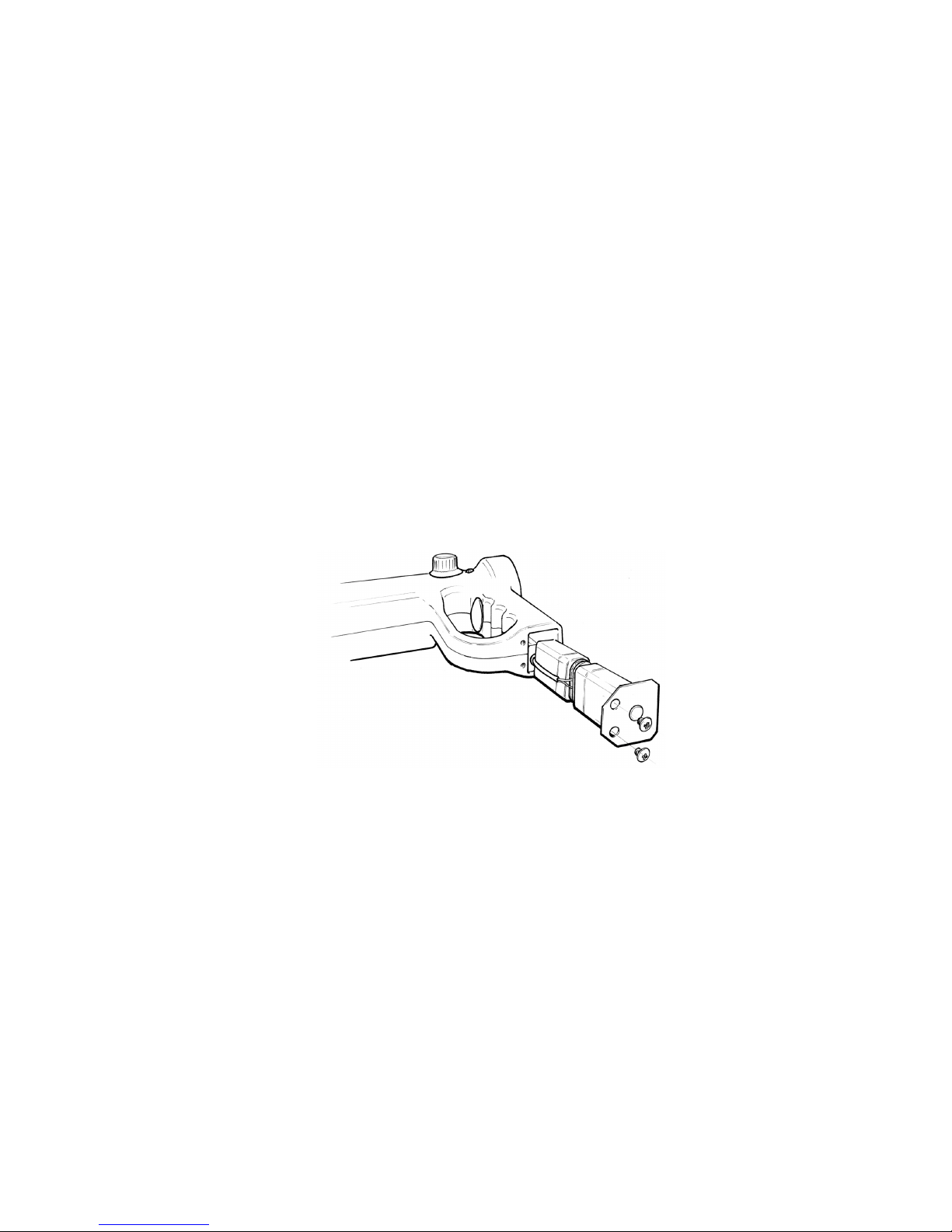
5.1 Battery replacement
Two # 522 standard 9-volt al aline batteries
power the Model 450. To access to the batteries,
remove the two screws at the bottom of the
handle and withdraw the battery cover plate. The
battery brac et is attached to the cover plate and
will come out when you remove the cover. If you
have difficulty gripping the cover plate, rotate it
90o and then pull the battery carriage out of the
grip.
Remove the old batteries and install the new
ones in position exactly as the ones you have
removed. When replacing your batteries ta e
care to not damage the wires and connector.
Reinsert the battery carriage into the Mag Horn
grip and secure the cover plate with the screws.

5.2 Warranty
THERE ARE NO WARRANTIES, EXPRESSED
OR IMPLIED, INCLUDING ANY WARRANTY OF
MERCHANTABILITY, BEYOND THOSE STATED
BELOW:
Utility Tool Company, Inc. arrants the MD450 Mag
Horn to be free from defects in orkmanship or
material under normal and proper use and service
for three years from the date of purchase by the
original user. Batteries are not included in this
Warranty. Unauthorized repair, alteration, or im-
proper maintenance ill nullify this Warranty.
Alteration or removal of the serial number ill also
void the Warranty. Utility Tool Company, Inc. ill not
be obligated under this Warranty if the equipment
has been misused, misapplied, or accidentally
damaged.
If a MD450 Mag Horn is found defective under this
Warranty, Utility Tool Company, Inc. ill, at its
option, repair or replace the unit free of charge at
the Utility Tool Company, Inc. factory. The unit
should be returned to the factory prepaid ith
customary shipping precautions. The
manufacturer’s obligations under this Warranty are
limited to the repair or replacement of defective
parts hich are not the result of alteration, misuse,
abuse, or accidental damage, or at the option of
Utility Tool Company, the refund of the purchase
price. Utility Tool Company, Inc. assumes no other
liabilities, contingent or consequential, to any
defective equipment.
17

5.3 Repair Service
When sending your Model 450 to us for repairs, please
provide details related to the problem ith your unit. This
ill help us expedite your repair and provide our techni-
cians ith the information they need to do the best job
possible.
For fast service (usually less than 48 hours),
return the Model 450 Mag Horn locator to:
Utility Tool Company, Inc.
Attn: Repair Dept.
2900 Commerce lvd.
irmingham, AL 35210
USA
Phone 205-956-3710
If you have questions or suggestions regarding our equip-
ment or a particular application, contact our contractor
applications support group at the number listed above
bet een 8:00 AM and 4:30 PM Central Time. Than you
for purchasing Pipehorn equipment. We value your busi-
ness and ant to keep it. Fill in the follo ing for your
records:
Mag Horn Model 450 Serial Number ________
Date of Purchase ___________
18

6 “User’s Hotline” 1-800-952-3710
Should you ever have questions or comments
concerning the operation or use of the Model 450 Mag
Horn, please call us at the number listed above. We
value your opinions and ant to hear from you.
Our office hours are Monday through Friday,
from 8:00AM to 4:30 PM Central Time.
You may also contact us via e-mail at: [email protected].
19

450manual_v0807.pdf
Table of contents
Other Pipehorn Measuring Instrument manuals

Popular Measuring Instrument manuals by other brands


AQUALEAK
AQUALEAK 10K Installation and operation manual

MR
MR MSENSE DGA 2/3 operating instructions

S+S Regeltechnik
S+S Regeltechnik RHEASREG KLSW Operating Instructions, Mounting & Installation

Tektronix
Tektronix 7L13 instruction manual

Hioki
Hioki 2300 Smart Site instruction manual

IPT
IPT ER 90 M/E A1114 Operation and maintenance manual

Anaheim Scientific
Anaheim Scientific H100 instruction manual

MOBILTEX
MOBILTEX RMU1 Installation and configuration guide

HOKUYO AUTOMATIC
HOKUYO AUTOMATIC UHG-08LX instruction manual

Dwyer Instruments
Dwyer Instruments PUX2 instruction manual

Metrohm
Metrohm FOSS NIRS XDS MultiVial Analyzer manual

Sontex
Sontex Supercal 739 installation guide