Pipehorn Series 800-H User manual

Series 800-H
High-Frequency
Pipe and Cable Locator
User Manual
Manufactured Exclusively By
:
Utility Tool Company, Inc.
2900 Commerce Boulevard
Birmingham, labama 35210
Tel 205-956-3710
Fax 205-956-3711
view instructional videos at:
www.pipehorn.com

D NGER! SHOCK H Z RD
CONNECTING DIRECTLY TO ANY
CONDUCTOR CAN BE HAZARD-
OUS AND RESULT IN ELECTRIC
SHOCK, INJURY, OR DEATH.
ONLY LICENSED OR AUTHOR-
IZED PERSONS SHOULD MAKE
DIRECT CONNECTIONS TO PO-
TENTIALLY ENERGIZED CON-
DUCTORS.
This devi e omplies with Part 15 of the
FCC Rules. Operation is subje t to the
following two onditions: (1) this devi e
may not ause harmful interferen e, and
(2) this devi e must a ept any interferen e
re eived, in luding interferen e that may
ause undesired operation.
NOTICE
This User’s Manual is provided as an infor-
mational guide only and is subje t to
hange without noti e.
This Manual ontains ertain information
whi h is proprietary in nature and prote ted
by U.S. and Foreign Patents, Copyrights,
and Registered Trademarks. All rights are
reserved. No part of this do ument may be
photo opied, reprodu ed, transmitted, or
onverted into another language without
the express written onsent of Utility Tool
Company, In .
Copyright © Utility Tool Company, In 2015
2

CONT NTS
General Information
Equipment List
Advantages of the 800-H
APWA Uniform Color Code
Terminology
The Equipment
The Transmitter
The Re eiver
The Signal
Pinpointing
Inductive Locating
Apply the HF Signal
Determine the Sour e of Signal
Verify the Condu tor Pinpointed
Search and Sweep
One Person
Two Person
Conductive Locating
Applying Signal to the Condu tor
System Check
Maintenance
Warranty
Repair Service
4
4
5
6
7
8
8
8
10
11
12
12
13
14
15
15
16
18
18
20
21
22
23
3

G N RAL INFORMATION
The Pipehorn Series 800-H is a state-of-the-art, single-
frequen y, pipe and able lo ating system designed for the pro-
fessional with omplex lo ating jobs. It is a arefully engineered,
pre ision instrument that, with reasonable are, will give many
years of satisfa tory servi e. The 800-H is very simple to oper-
ate, but for best results, the operator should arefully read this
manual.
The 800-H an operate as a high-frequen y indu tive or ondu -
tive lo ator.
This equipment is used to lo ate and tra e all types of buried or
on ealed ondu tors su h as: pipe, able, tra er wire, tra eable
fiber opti s, or even sewer snakes or fish tape inserted into non-
ondu tive pipe. The 800-H has an audible response as well as
a visual response to help verify the lo ate and to help give an
estimated depth.
Equipment List
The 800-H onsists of the following:
1
Re eiver
2
High-Frequen y
Transmitter
3
Set of Condu tive
Cables
4
Ground Rod
5
Qui k Guide
6
Instru tion Manual
7
Vinyl Carrying Case
4

dvantages of the 800-H
Every lo ating job is different. Su ess alls for a unique blend
of equipment, experien e, and persisten e. In some situations,
a low-frequen y, ondu tive lo ator will perform better than a
high-frequen y, indu tive lo ator. In other situations, the reverse
is true.
The advantage of the high-frequen y is that it tra es poor on-
du tors, an lo ate short lengths better than the low-frequen y,
and it does not have to be dire tly onne ted, though this
method is available. Indu tive operation is mu h faster and eas-
ier allowing the operator to move the signal to any pla e whi h is
useful. The disadvantage of high-frequen y during indu tive
lo ating is that it an pla e more signal on adja ent ondu tors,
making isolation more diffi ult.
The 800-H is apable of both indu tive and ondu tive modes.
During ondu tive mode the high-frequen y no longer indu es
signal whi h helps isolate the target.
The Re eiver has a meter to show signal strength whi h is help-
ful in noisy situations. This meter also aids in depth estimation.
We have also tuned the Re eiver’s audio feedba k to produ e
tones that are most audible by the human ear.
5

S FETY FIRST!
D NGER! Shock Hazard. Connecting directly to any con-
ductor can be hazardous and result in electric shock, injury,
or death. Only licensed or authorized persons should make
direct connections to potentially energized conductors.
Always exer ise good safety pro edures when operation lo ating
equipment. These in lude, hooking a transmitter dire tly to ener-
gized ondu tors only when li ensed or authorized, being on-
stantly aware of traffi and equipment operating nearby, and re-
moving any flammable or toxi liquids and gases from the area
before using a lo ator.
Employing proper safety practices during locating tasks will
perhaps avoid an accident and may save your life.
PW Uniform Color Code
Use this ode for marking buried utilities. This ode is used to
identify the various types of underground utilities. Make sure the
olor you use orresponds to the hart below for the type of util-
ity you are marking.
Electric Power Lines or Conduits
Communication Lines or Cables
Storm & Sanitary Sewers
Water
Proposed Excavation rea
- Safety Red
- Safety lert Orange
- Safety Green
- Safety Precaution Blue
- High Visibility White
6

T RMINOLOGY
When the following terms are used in this manual, they have the
meanings spe ified below:
Conductor - pipe, able, onduit, tra eable opti fiber, tra er
wire/tape, sewer snake, fish tape, or other lines needed to
find.
Tracer Signal or Signal - the output from a transmitter, either
dire tly or through the air, whi h is arried along the ondu -
tor and dete ted with the Re eiver.
Inductive - pla e the tra er signal on the ondu tor without
making a dire t ele tri al onta t.
Conductive - pla e the tra er signal on the ondu tor by mak-
ing a dire t ele tri al onta t or “dire t-hookup”
HF - high-frequen y
Sensitivity - the amount of signal the Re eiver is set to dete t;
in reasing the sensitivity allow the Re eiver to dete t weaker
signals when it is farther from the Transmitter or ondu tor,
as the ase may be. Also known as “GAIN”
Saturated Tone - when the Re eiver sensitivity is set too high
and the tone no longer hanges as you pass over a ondu -
tor. In other words the Re eiver is re eiving too mu h signal
from the Transmitter and an no longer pinpoint the line.
The 800-H Re eiver will beep during saturation. Lower the
sensitivity to eliminate saturation and allow for better pin-
pointing.
Search & Sweep - refers to s anning the area using the high
frequen y to find all of the ondu tors in the ground. Can be
performed by one or two people.
7
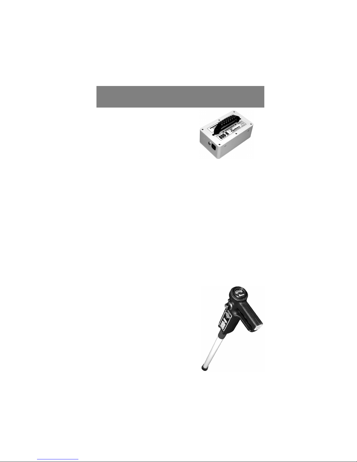
TH QUIPM NT
Transmitter
Modes: Indu tive - HF
Condu tive - HF
Signal Clamp - HF
During Inductive Mode the High-Frequen y is being indu ed.
To put the most signal on a ondu tor, pla e the handle of the
Transmitter in-line and dire tly over the ondu tor.
During the Conductive or Signal Clamp Mode the high-
frequen y is no longer indu ing and all signal is fo used on the
target ondu tor. For maximum benefit, pla e the ground rod as
far away as possible at 90° from the ondu tor. Remember to
ground away from trouble in luding adja ent ondu tors, fen es,
& other metalli stru tures
The 800-H Transmitter produ es an audible tone when the unit is
ON. When the tone is a high pit h, then a good signal is being
put out. If during Condu tive mode, a low pit h is heard then
there is poor signal being pla ed on the ondu tor. This ould
be due to a bad ground or poor onne tion to the pipe, et . If the
Transmitter starts beeping then the batteries are getting low.
Receiver
The Re eiver an be used during
all modes des ribed above. Signal
response feedba k is given by an
audio speaker and a meter.
8

Receiver Continued...
To turn the 800-H Re eiver ON,
simply turn the sensitivity knob
until it li ks.
The higher the number on the
knob, the more sensitive the Re-
eiver is.
Higher No. = More sensitivity
The sound the re eiver makes is as follows:
High Pit h = lose to ondu tor
Low Pit h = moving away from ondu tor
Beeping = sensitivity is too high
Both the audio speaker and the meter let you know when the
Re eiver is over a ondu tor.
When the needle on the meter rea hes 10 it is at peak signal.
Beyond 10 the signal be omes saturated and you need to lower
the sensitivity.
To save battery life, the Re eiver turns itself OFF after 5 minutes
of no use. To reset the Re eiver and turn it ba k ON, simply turn
the swit h OFF and ba k ON.
9
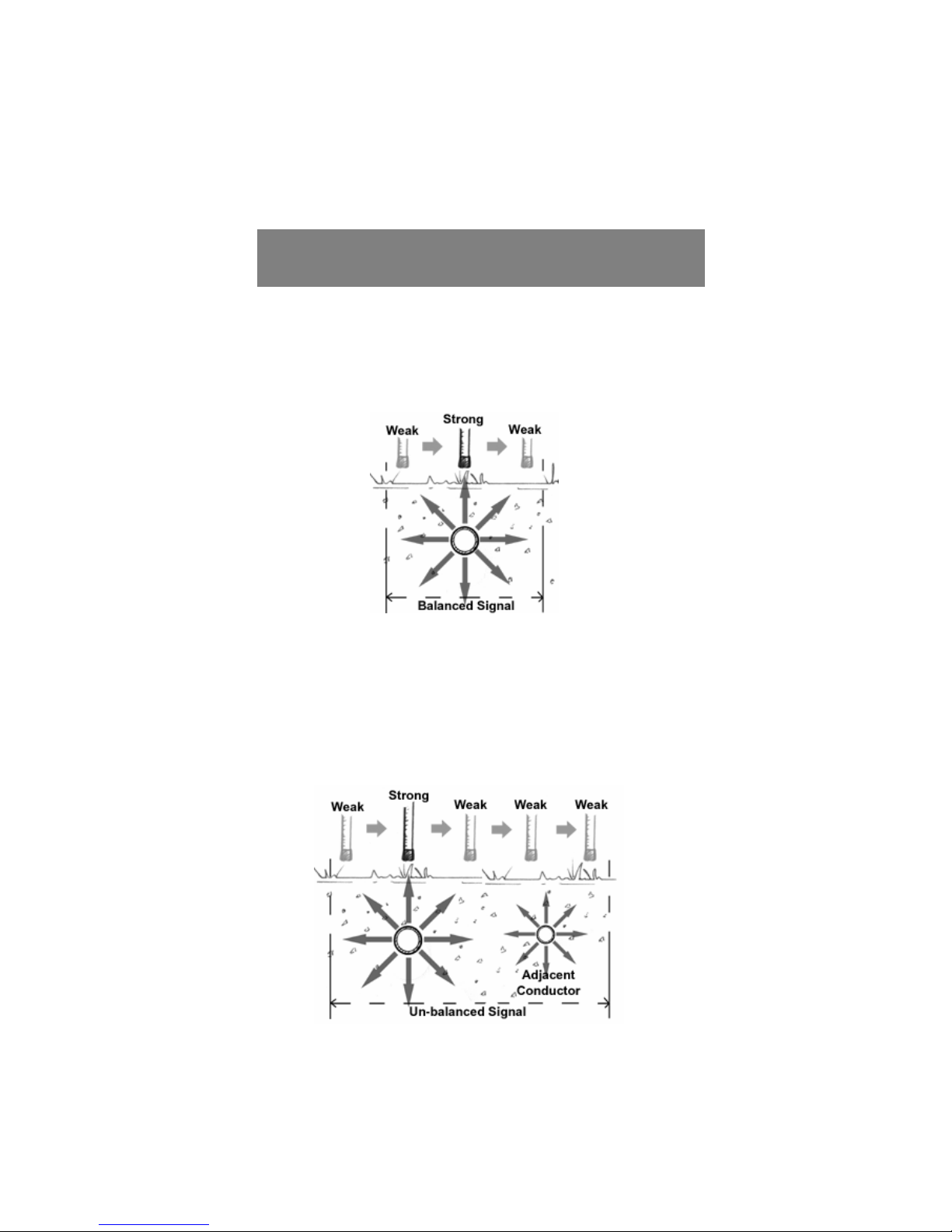
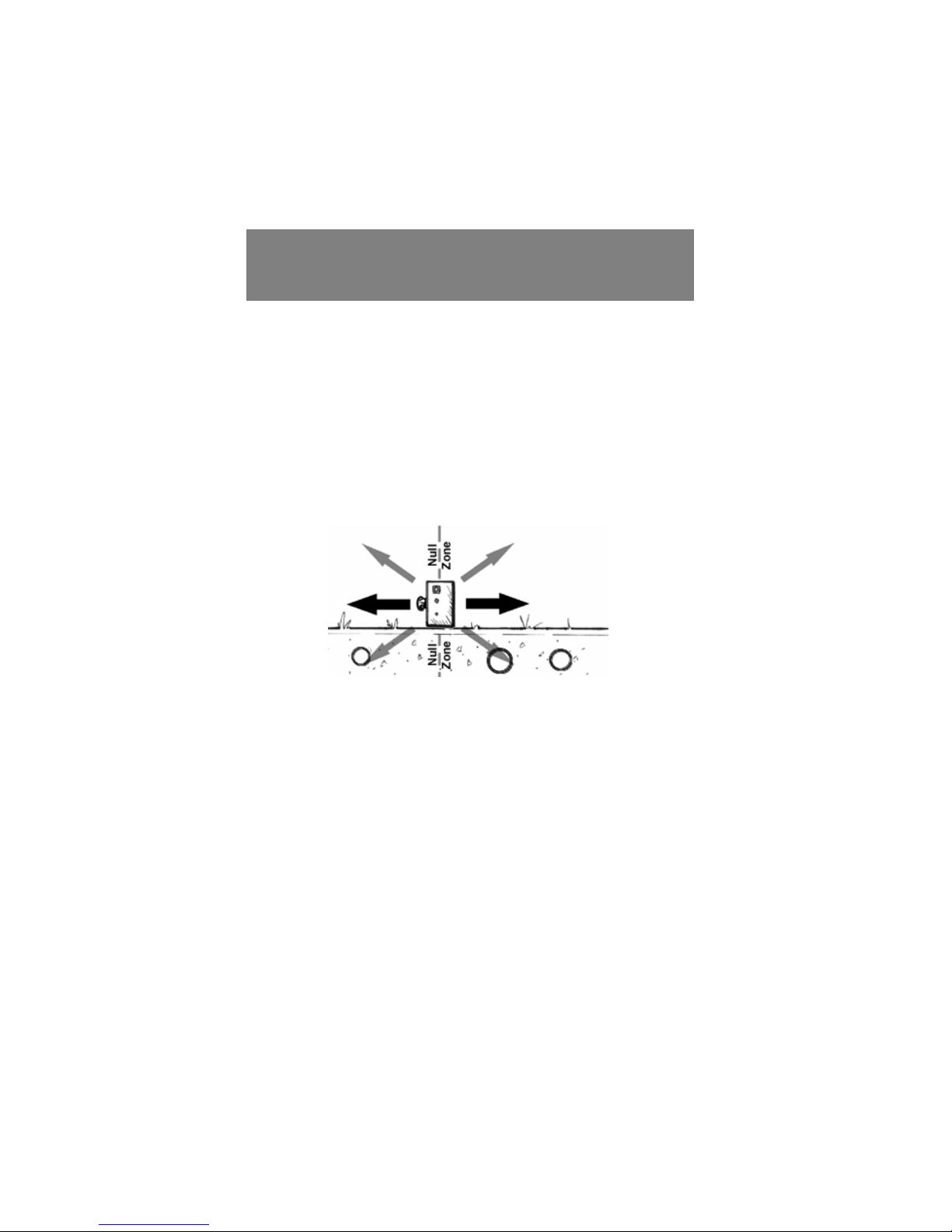
TH SIGNAL
At any given distan e, say 2 feet, at any dire tion from the on-
du tor, the strength of the signal is the same under most ondi-
tions. This allows the Re eiver to pinpoint dire tly over the on-
du tor, as shown below, be ause that is the area with the peak
(strongest) signal reading.
While lo ating always hold the Re eiver verti ally, and in the
dire tion of the pipe (in-line with the handle). Swinging the Re-
eiver as you s an may lead you to interpret the signal in or-
re tly.
Under ideal situations you will re eive a balan ed signal, as
shown above. However, in some ases an un-balan ed signal
will o ur, usually due to interferen e from another ondu tor, as
shown below.
10
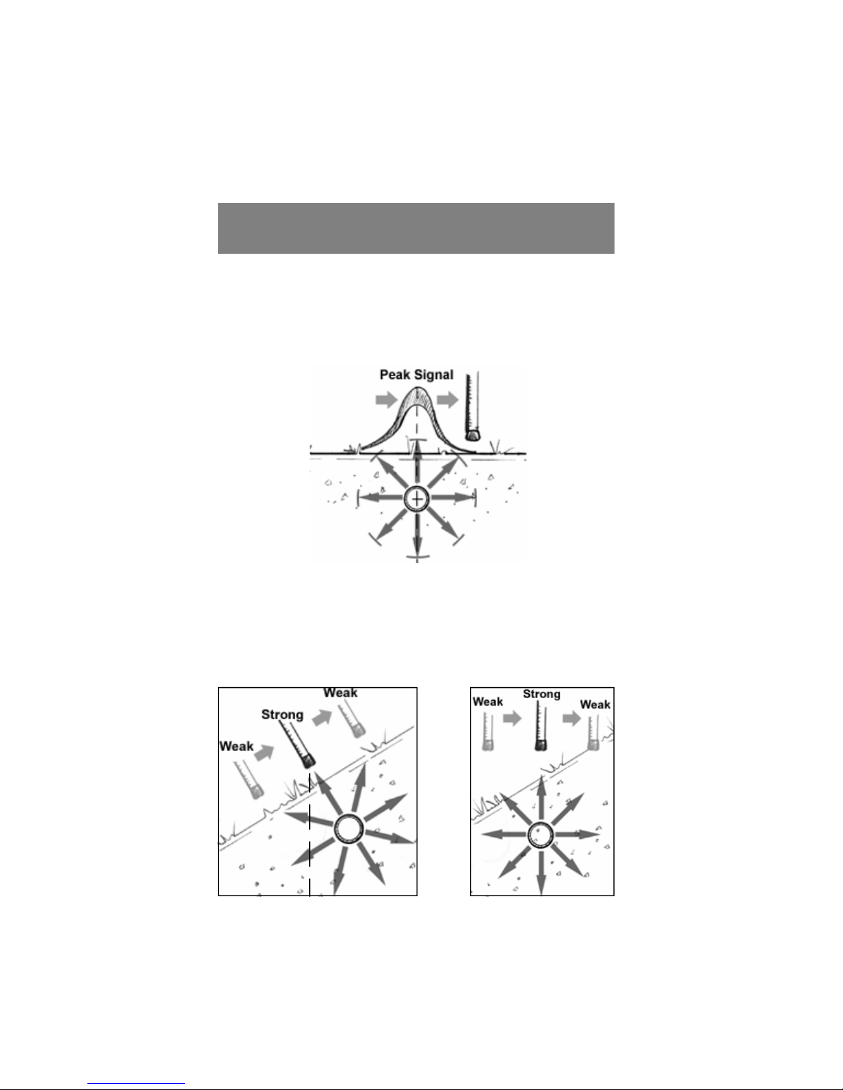
INCORRECT CORRECT
As you move loser to the ondu tor the Re eiver’s sound be-
omes a higher (shrill) pit h. As you move away from the on-
du tor the pit h lowers and will eventually go away. lways
maintain a solid, non-beeping tone from the Receiver to en-
sure proper alignment with the conductor.
PINPOINTING
Be areful when on a hill or steep bank. Try to keep the Re-
eiver level, not parallel to the hill. The Re eiver will go towards
the strongest tone, and if it is kept parallel to the hill side that
tone will NOT be dire tly over the ondu tor as shown below.
The deeper the ondu tor is, the worse this problem be omes.
11
INDUCTIV LOCATING
This method is used when there is no dire t a ess to the target
ondu tor. It is also helpful in finding ondu tors with lo ations
that are unknown.
With the 800-H the High-frequen y is indu ed onto the ondu -
tor. It will only do so when the onne tion ables have been dis-
onne ted from the Transmitter.
Starting From a Known Point
Use the following steps to begin tra ing a ondu tor from a
known point su h as, a meter, valve, pedestal, or line marker,
where a ess to the ondu tor for dire t hook-up is not possible
or is prohibited.
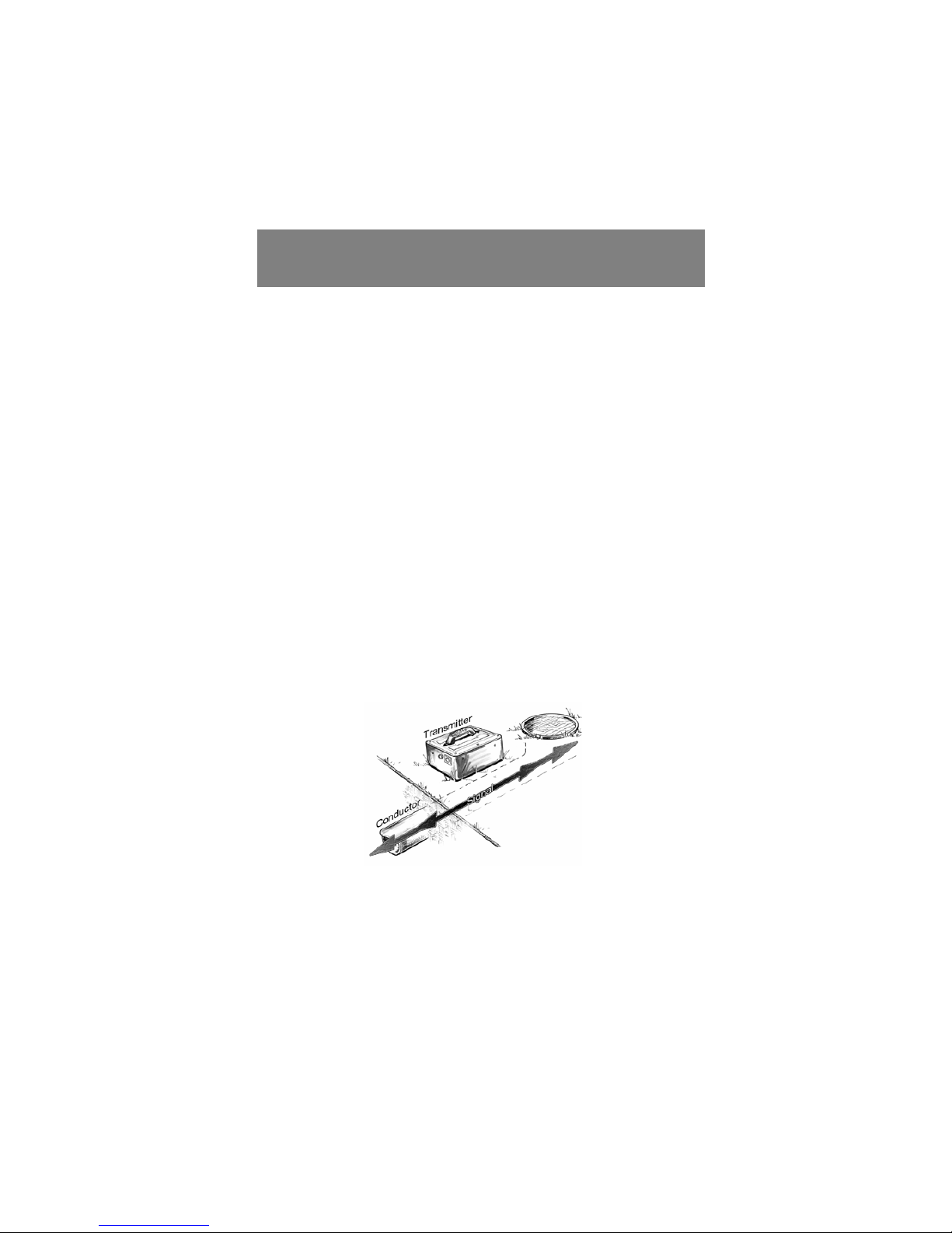
pply the HF Signal
Pla e the 800-H Transmitter dire tly over the ondu tor with the
handle in-line with the ondu tor, as shown below. Careful align-
ment and pla ement of the Transmitter will maximize the signal
on the ondu tor. Turn the Transmitter ON.
Set Up the Receiver
Depending on the depth of the ondu tor, move 20-30 feet away
from the Transmitter. The deeper the ondu tor, the farther
away from the Transmitter you must start. Fa e the Transmitter
and position the Re eiver antenna near the ground. Set the Re-
eiver to re eive High-Frequen y as explained on page 8. Move
the sensitivity knob lo kwise to turn the re eiver ON.
12

Set Proper Sensitivity & Scan the rea
Adjust the sensitivity knob to get a solid, non-beeping tone from
the Re eiver. S an to the left or right to find the stronger signal.
The higher pit h sound indi ates you are getting loser to the
ondu tor, a lower pit h sound indi ates you are moving away
from a ondu tor. If the sound starts beeping, lower the sensitiv-
ity and ontinue s anning.
Pinpoint the Conductor
When s anning and the sound peaks, or hanges from LOW to
HIGH to LOW pit h, then you have ome a ross the ondu tor.
Be sure the tone dies off evenly on both sides of the peak (letting
you know you have a balan ed signal). The peak, or highest
pit h, indi ates when the antenna is dire tly over the ondu tor
as des ribed on page 11.
Determine Source of Signal
After pinpointing, raise the re eiver antenna and point it at the
Transmitter. If the signal does not get signifi antly weaker, then
the signal is oming through the air from the Transmitter more so
than from the ondu tor. There may be no ondu tor or you
may be too lose to the Transmitter. Move farther away from the
Transmitter, pinpoint again, and re- he k as shown below.
13

Verify the Conductor Pinpointed
Mark the spot where you have pinpointed the line and he k the
dire tion by twisting the Re eiver left and right to get the strong-
est signal.
Now pla e the Transmitter on the mark, in-line with the ondu -
tor, and tra e the ondu tor ba k to its sour e.
Trace the Conductor’s Path
When satisfied that you’ve found the target ondu tor, begin
walking away from the Transmitter, tra ing the path of the on-
du tor by sweeping the antenna left and right. Always keep the
antenna level and listen for the LOW-HIGH-LOW sound hange.
Tra e as far as ne essary adjusting the sensitivity ontrol to
maintain a solid, non-beeping tone.
Weak or Confusing Signal
When the sensitivity ontrol is fully lo k-wise or the tone be-
omes jittery or un lear, reposition the Transmitter at the last
lear lo ation and ontinue tra ing.
14
S ARCH AND SW P
One Person
This te hnique is benefi ial in finding ondu tors with unknown
lo ations, and with no a ess points. Basi ally you use the
equipment in a way that s ans the entire ground to find all on-
du tors in a spe ifi area. Please read the instru tions for indu -
tive lo ating before pro eeding.
Position the Transmitter
Lay the 800-H Transmitter on its side, as shown below. This will
“flood” the area with signal. Turn ON the Transmitter.
Set Up the Receiver
Set up with the Re eiver the same as you would during indu tive
lo ating. Move 5-10 feet from the Transmitter, fa e the Trans-
mitter with the antenna near the ground, and turn the Re eiver
ON. Set the sensitivity control so that the meter reads 4 and
you hear a LOW pitched tone.
Locate the Conductor(s)
With the re eiver fa ing the Transmitter, walk in a ir le around
the Transmitter. Keep a steady distan e from the Transmitter
and from the ground. Listen for the HIGH pit h tone areas, DO
NOT adjust the sensitivity. After lo ating the HIGH pit h areas,
go ba k and pin-point the ondu tors in those areas. You may
need to re-adjust the sensitivity at this step, looking for the LOW-
HIGH-LOW sound hange. Mark the pla es with the highest
tones for further pinpointing later.
15

For Full Coverage
Re-lo ate the 800-H Transmitter at least on e several steps to
the right or left in order to provide omplete overage. This is
be ause any ondu tor whi h is dire tly underneath the Trans-
mitter will not be dete ted.
Pinpoint and Determine Signal Source
As with normal Indu tive Lo ating, pla e the 800-H Transmitter
upright on one of the marks made earlier, (in line with the sus-
pe ted run of the ondu tor). Pinpoint the ondu tor on the
other side of the sear h area in the normal manner, as des ribed
on page 11.
After pinpointing the ondu tor, raise the re eiver toward the
Transmitter to be sure the signal is mostly oming from the on-
du tor and not through the air, as des ribed on page 13.
Repeat this pro ess for ea h of the HIGH pit h areas found ear-
lier and mark the lines a ordingly.
S ARCH AND SW P
Two Person
Generally, two people an perform a sear h over a broad area
qui ker than one person.
Set Up the Search
Start over an area where there are no ondu tors. One person
holds the Transmitter to his/her side in line with the suspe ted
run of the ondu tor(s). The other person stands approximately
30 feet away from the Transmitter, holding the Re eiver to his/
her side. (Be sure the re eiver is set to re eive High-frequen y,
page 8.) Turn both units ON, and keep them pointed at ea h
other. Set the Re eiver’s sensitivity ontrol so that the meter
reads 4 and you hear a LOW pit hed tone. The tone will get
higher as you get loser to ondu tors.
16
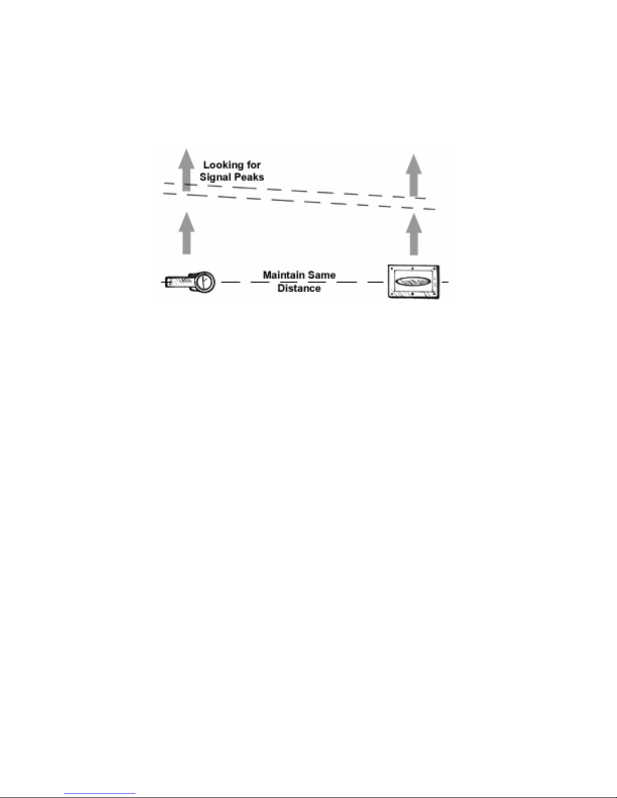
Sweep the rea for Conductors
Maintain a onstant distan e between the Re eiver and the
Transmitter. Move together a ross the area where the ondu -
tors are suspe ted to run. DO NOT adjust the sensitivity during
the sweep. When the operators sweep together over a ondu -
tor, the tone from the Re eiver will get HIGH (shrill) or begin
beeping, indi ating a stronger signal. Temporarily mark the high
pit h areas for pinpointing later.
Pinpoint and Determine Signal Source
Set the Transmitter down in one of the high pit h areas found,
and pinpoint with the Re eiver (page 11). After he king dire -
tion, get a good solid tone on the re eiver and let the other per-
son pinpoint using the Transmitter. Move the Transmitter left
and right until the re eiver gets the strongest (highest pit h) sig-
nal response. At this point the Transmitter and re eiver are di-
re tly over the ondu tor.
After pinpointing the ondu tor, raise the re eiver toward the
Transmitter to be sure the signal is mostly oming from the on-
du tor and not through the air, as des ribed on page 13.
Conductors Going in Different Directions
Set up as before in different dire tions to sweep the area for on-
du tors running at 45° and 90° to the original lo ating position.
17
Conductive Locating
Condu tive lo ating is done when there is an a ess point avail-
able for dire t onne tion to the target ondu tor. This te hnique
applies maximum signal to the target ondu tor with minimal
signal applied to adja ent ondu tors.
The 800-H puts out the High-frequen y during Condu tive Lo at-
ing. Condu tors, su h as deep high-pressure gas mains, om-
muni ation ables, and other insulated ontinuous pipes and
ables, tra er wire and tape whi h may have breaks, as well as
poor ondu tors like ast iron with partially insulating ouplings
are all andidates for HF lo ating.
Only li ensed or authorized persons should make dire t onne -
tions. DO NOT HOOK DIRECT TO LIVE POWER CABLES.
Make ertain that the owner of the ondu tor has authorized di-
re t hook-up for purposes of lo ating.
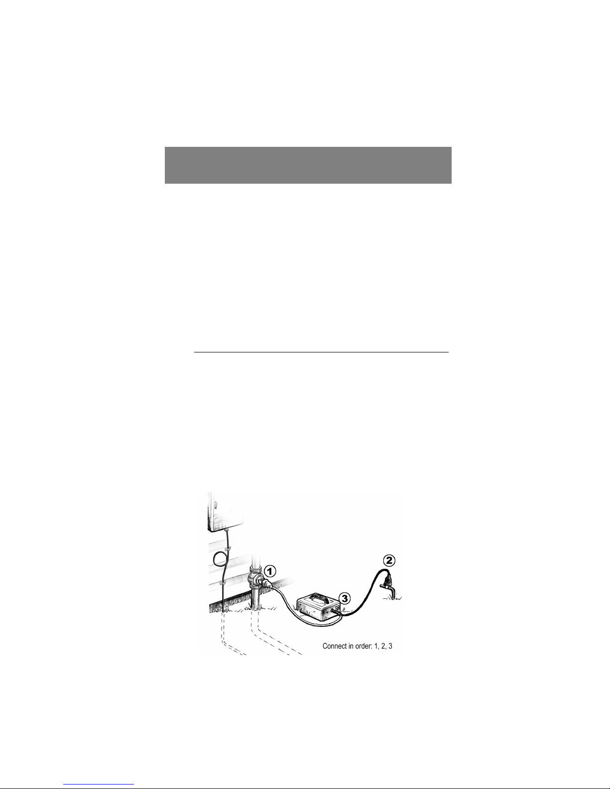
ppling Signal to the Conductor
Remove any rust, paint, or other insulating substan es from the
point of onta t with the ondu tor.
Position the supplied Ground Rod as far away from and 90° from
the ondu tor as possible. Try to avoid grounding over an adja-
ent ondu tor. Conne t to the Condu tor, then to Ground, then
insert the phono plug into the ja k, and last, turn the Transmitter
ON.
18

Trace the Conductor
From the Re eiver sele t whi h frequen y you wish to tra e with.
Sometimes one frequen y will tra e better than the other. Step a
few feet from the Transmitter in the dire tion of the suspe ted
ondu tor and set the sensitivity to get a solid steady tone from
the Re eiver.
Begin walking away from the Transmitter along the path of the
ondu tor while sweeping the re eiver’s antenna left and right
maintaining the LOW-HIGH-LOW tone pattern.
Verify the Conductor
After marking the ondu tor along the path away from the Trans-
mitter (30 ft. re ommended), move the transmitter to that spot
and indu tively tra e ba k to the sour e point (as des ribed on
page 14. This will help ensure that you are on the right ondu -
tor.
For other lo ating tips, all us at 205-956-3710 or he k out our
website at www.pipehorn.com.
19

System Check
20
Verifying the Transmitter, Re eiver, Condu tive Cables, and optional
Signal Clamp are operational before use is re ommended.
Check Induction
Pla e the transmitter on the ground away from utility lines and other
interfering metal obje ts, su h as vehi les and fen es. Turn it on and
listen for the high-pit hed tone indi ating good battery and good signal.
Set the Re eiver’s sensitivity knob pre isely at 2. The Re eiver should
be beeping when against the Transmitter as shown. Move in a line
away from the Transmitter. The beeping tone should ontinue for at
least 3 feet.
Check Conduction & Clamp
Plug the ondu tive ables into the Transmitter. The Transmitter makes
a low tone be ause the lips are not onne ted to anything. Conne t
the lips together. A high-pit hed tone from the Transmitter indi ates
good signal and good ables. Pla e the ables in a loop. With the knob
still at 2, tou h the Re eiver to the red wire keeping the handle in-line
with the wire as shown. A beeping tone from the Re eiver indi ates
ondu tion is operational. To he k the optional Signal Clamp, plug it
into the Transmitter and listen for the good signal tone. Pla e the Re-
eiver tip inside the Clamp’s ring. A beeping tone from the Re eiver
indi ates the Clamp is operational.
If the lo ator fails the he ks above, or if the Transmitter makes a beep-
ing tone, or if the Re eiver’s volume is low, repla e batteries and repeat
he ks. If it fails again with good batteries, the lo ator may need repair.
This manual suits for next models
1
Table of contents
Other Pipehorn Measuring Instrument manuals

Popular Measuring Instrument manuals by other brands

Critical Environment Technologies
Critical Environment Technologies FCS installation manual

Flexim
Flexim FLUXUS F704**-NN Series user manual

Hanna Instruments
Hanna Instruments HI 717 quick start guide

QUNDIS
QUNDIS Q Water 5.5 installation instructions

Muller Ziegler
Muller Ziegler DSMG 96 manual

socomec
socomec COUNTIS M33 manual


