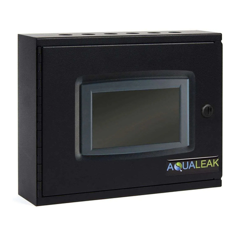
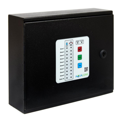
AQUALEAK 10K User manual

10K manual
Issue 1.0, 31st July 2019 Page 2
PREFACE
Published by Aqualeak.
All possible care has been taken in the preparation of this manual, but Aqualeak, its agents
and distributors accept no liability for any inaccuracies that may be found. This manual
reflects the state of the product at the issue date below, but further enhancements while in
service may mean that the manual does not precisely reflect your system.
Aqualeak reserves the right to make changes without notice both to this manual and the
products which it describes.
Issue 1.0, 31st July 2019
Firmware version: 3.2
Aqualeak shall not be liable for errors contained herein or for incidental or consequential
damages in connection with the furnishing, performance or use of this manual.
Copyright: © Aqualeak 2019
All rights reserved.
No part of this publication may be reproduced, stored in a retrieval system or transmitted in
any form or by any means electronic, mechanical, photocopying, recording or otherwise
without the express prior written permission of the copyright holder.
Contact Details:
Aqualeak Detection Ltd,
11 Forest Gate, Pewsham,
Chippenham.
Wiltshire.
SN15 3RS
United Kingdom
If you require technical assistance with this product that is not covered within this manual,
then help can be requested from Aqualeak or our distribution partners.
General enquiries about this or other Aqualeak products should be sent to
All trademarks used within this document are the property of their respective owners.

10K manual
Issue 1.0, 31st July 2019 Page 3
Only for EC countries:
Do not dispose of measuring tools into household waste!
According the European Guideline 2002/96/EC for Waste Electrical and
Electronic Equipment and its implementation into national right, measuring
tools that are no longer usable must be collected separately and disposed of in
an environmentally correct manner.
SAFETY WARNINGS
WARNING –ELECTRIC SHOCK
The Aqualeak 10K operates using mains voltage that is dangerous to life. Before
work commences, make sure that the mains power is isolated by a competent
person and a Lock Out and Tag-Out procedure has been followed. Prove the mains
supply is de-energised with a suitable multi-meter which has been checked with a proving
unit.
Death, personal injury and/or damage to persons and/or property may result if this is not
observed.
LIST OF ABBREVIATIONS
Below is a list of standard abbreviations used in this manual.
A Amp
AC Alternating current
BIT Built In Test
BMS Building Management System
C Celsius
Comms Communications
dB decibel
DC Direct current
Deg Degree
EC European Commission
EOL End of Line
g gram(s)
Hz Hertz
IEC International Electrotechnical Commission
IP Ingress protection
kg kilogram

10K manual
Issue 1.0, 31st July 2019 Page 4
LED Light Emitting Diode
Lsb Least significant bit
M Metre
min minutes
mm millimetre
Msb Most significant bit
msec milli-second
Nm Newton metre
No. Number
PSU Power Supply Unit
RTU Remote Terminal Unit
sec seconds
VAC Volts (Alternating Current)
VDC Volts (Direct Current)
W Watts

10K manual
Issue 1.0, 31st July 2019 Page 5
CONTENTS
Page
PREFACE .......................................................................................... 2
Safety Warnings .................................................................................... 3
List of Abbreviations .............................................................................. 3
CONTENTS (this list) .............................................................................. 5
FIGURES .......................................................................................... 6
TABLES .......................................................................................... 6
INTRODUCTION AND PRODUCT OVERVIEW ..................................................... 5
DESCRIPTION ....................................................................................... 8
Supervised system ............................................................................ 8
Sensors available ............................................................................. 8
Distance Read Leak Detection .............................................................. 8
Front panel .................................................................................... 8
Internal description .......................................................................... 9
Supplied items ..................................................................................... 9
Additional Items ................................................................................... 10
Specification ....................................................................................... 11
INSTALLATION AND CONFIGURATION ........................................................... 12
Preparation for installation ...................................................................... 12
Installing the Aqualeak 10K ...................................................................... 12
Establish Physical Connections .................................................................. 12
TB1 Summary Relay (optional) .............................................................. 14
TB2 Leader Cable ............................................................................. 14
TB3 and TB4: Input Power and EIA-485 communications ports ........................ 15
JMP - Termination Jumper ................................................................... 17
Select Alarm Options .............................................................................. 17
Enable and Disable the Audible Alarm ..................................................... 17
Set the Re-Alarm interval ................................................................... 17
Connect the Leak Detection Cable .............................................................. 18
Connect lengths of sensor cable ............................................................ 18
Secure sensor cable to the floor ............................................................ 19
Applying power to the Aqualeak 10K ........................................................... 20
Test the System .................................................................................... 21
OPERATION ......................................................................................... 22
Front Panel Controls and Display ................................................................ 22
Manage Alarms ..................................................................................... 24
General Guidance ............................................................................ 24
Contamination Alarm Guidelines ........................................................... 24
MODBUS COMMUNICATIONS ...................................................................... 25
Modbus Implementation Basics .................................................................. 25
Modes of Transmission ....................................................................... 25
Slave Address Field ........................................................................... 25
Function Field ................................................................................. 25
Data Field ...................................................................................... 25
Error Check (Checksum) Field .............................................................. 25
Exception Responses ......................................................................... 25
Packet Communications for the Aqualeak 10K ................................................ 26
Function 03: Read Output Registers ....................................................... 26
Function 04: Read Input Registers ......................................................... 28
RTU Framing ....................................................................................... 29
Calibrate sensor cable length via Modbus ...................................................... 30

10K manual
Issue 1.0, 31st July 2019 Page 6
PREVENTIVE MAINTENANCE ...................................................................... 32
Monthly maintenance ........................................................................ 32
TROUBLESHOOTING ............................................................................... 33
Repair .......................................................................................... 34
APPENDIX A –CONFIGURATION REFERENCE .................................................... 35
A1. DIP Switches ................................................................................... 35
A2. SW1 DIP Switch settings ..................................................................... 36
A3. SW2 DIP Switch settings ..................................................................... 37
A3.1 Configure the Aqualeak 10K for Modbus Communications ........................ 37
FIGURES
Page
Figure 1 Aqualeak 10K ......................................................................... 7
Figure 2 Aqualeak 10K controls and indicators ............................................ 9
Figure 3 Aqualeak 10K interior ............................................................... 10
Figure 4 Electrical connections to Aqualeak 10K .......................................... 13
Figure 5 Relay Output Connection TB1 ...................................................... 14
Figure 6 General DIP Switch settings ........................................................ 14
Figure 7 SW1, DIP Switch 5 –Latched or Unlatched Alarms .............................. 14
Figure 8 Cable connection TB2 ............................................................... 15
Figure 9 SW1, DIP Switch 6 –Display cable length in feet or meters ................... 15
Figure 10 SW1, DIP Switch 7 –Ohms per foot resistance .................................. 15
Figure 11 TB3 and TB4 Power Supply and Communications connections ................ 16
Figure 12 DIP Switch settings for Communications Baud Rate ............................ 16
Figure 13 DIP Switch settings for Communications Address ............................... 17
Figure 14 DIP Switch 8, SW 1 - Audible Alarm Settings ..................................... 17
Figure 15 DIP Switch 4, SW1 - Re-Alarm Interval............................................. 18
Figure 16 Sensor cable .......................................................................... 18
Figure 17 Example of sensor cable routing in large data centre ......................... 19
Figure 18 Securing the sensor cable ........................................................... 20
Figure 19 Aqualeak 10K controls and indicators ............................................ 22
Figure 20 SW1 DIP Switch settings for Ohms/Foot .......................................... 30
Figure A-1 General DIP Switch settings ........................................................ 35
Figure A-2 SW1 DIP Switch configuration settings ........................................... 36
Figure A-3 SW2 DIP Switch settings for Modbus Unit Address .............................. 37
TABLES
Page
Table 1 10K specification .................................................................... 11
Table 2 Front panel controls and displays ................................................. 23
Table 3 Exception Codes ..................................................................... 26
Table 4 Read Output Registers Packet Structure ......................................... 26
Table 5 Output Registers ..................................................................... 26
Table 6 Read Input Registers Packet Structure ........................................... 28
Table 7 Input Registers ....................................................................... 28
Table 8 Status Flags (Register 30001) ...................................................... 29
Table 9 Response sample ..................................................................... 29
Table 10 Troubleshooting ...................................................................... 33

10K manual
Issue 1.0, 31st July 2019 Page 7
INTRODUCTION AND PRODUCT OVERVIEW
The Aqualeak 10K is a cost effective, distance-read, leak detection solution. The Aqualeak
10K uses sensing equipment (sold separately) to detect the presence of water and other
liquids. If a leak is detected, an alarm is activated, the distance to the leak is displayed, and
the Aqualeak 10K can report the presence of the leak to a Building Management System
(BMS).
Aqualeak 10K is a single zone system, designed for continuous operation with minimal human
intervention.
In operation, the Aqualeak 10K continuously monitors the sensor cables connected to it.
Figure 1 Aqualeak 10K

10K manual
Issue 1.0, 31st July 2019 Page 8
DESCRIPTION
Capable of accommodating up to 2500 m (8200 ft) of sensor cable, the Aqualeak 10K has an
audible alarm and can communicate via Modbus. As a stand-alone solution, the Aqualeak 10K
provides alarm notification, and numeric distances to leaks or problems, on its front panel.
Integration into a Modbus network allows the activity and status of one or multiple Aqualeak
10K’s to be managed from one central location.
Supervised System
The Aqualeak 10K is a supervised system –it continually monitors the sensor cable and spot
detectors for continuity and produces alarms for the following conditions:
1. Leak detection.
2. Cable break.
3. Cable contamination.
Sensors available
Water is detected using a sensor cable up to a maximum length of 2500 m (8200 ft). Only use
the recommended type of sensor cable supplied by Aqualeak in conjunction with the 10K.
Although not normally installed, spot detectors may be used with the 10K. Contact Aqualeak
for more details.
Distance-Read Leak Detection
When the Aqualeak 10K's circuitry measures a current in excess of the user-defined leak
threshold, the unit's microprocessor computes the distance to the leak. The Aqualeak 10K then
sounds an alarm and communicates via Modbus to a master controller or a Modbus- equipped
monitoring system. The summary relay sends notification to an alarm panel or monitoring
system.
Front panel
The 10K’s front panel display (Figure 2) includes a four-digit LED panel and six LED indicators
that provide information about its status, including the following:
•Leak detected;
•Distance to leak or contamination;
•Cable fault detected;
•Power status;
•Configured unit of measure;
•Leak detection cable’s amperage value;
•Length of installed leak detection cable;
•Self-test results.

10K manual
Issue 1.0, 31st July 2019 Page 9
The two blocks of DIP switches on the 10K’s front panel are used for configuration. DIP SW1
configures parameters such as leak and contamination thresholds, latching alarms, and re-
alarm time interval. DIP SW2 is used to set the Modbus address information for the 10K.
The 10K also provides configuration capability and status information to a Modbus equipped
system via its EIA-485 port.
1 Four-character LED display 4 DIP switch SW2 –Modbus Configuration
2 LED’s 5 Test/Reset/Alarm/Silence push-button
3 DIP Switch SW1 –Configuration Settings
Figure 2 Aqualeak 10K controls and indicators
Internal description
Please refer to Figure 3. The active components of the Aqualeak 10K are the 10K Controller
and the associated Power Supply Unit (PSU). They are mounted on a standard DIN rail inside
the back box of the 10K casing. To the left of the PSU are DIN rail mounted terminal blocks
for the mains supply live, neutral and Earth connections.
The 10K Controller contains two circuit boards. The top circuit board houses the operational
controls and displays. The lower circuit board houses connectors for the leak detection sensor
cable, relay outputs, communications and AC/DC power, and Earth.
If the 10K requires repair and service, it must be either returned to Aqualeak, or an Aqualeak
Installation Engineer called-out.
SUPPLIED ITEMS
The Aqualeak 10K, as supplied, comprises the following items. Before installing the 10K,
check that all items are present and undamaged:
1. The 10K unit, shown on the front cover of this manual.
2. A 4.57 m leader cable, that is used to connect the sensor cable to the Aqualeak 10K.
3. An End Of Line (EOL) terminator.

10K manual
Issue 1.0, 31st July 2019 Page 10
1 Power Supply Unit 7 Relay Output (TB1)
2 Earth bus bar 8 Sensing Cable connector (TB2)
3 AC/DC power and EIA-485 Comms Port 9 Live terminal block
4 Neutral bus bar 10 Neutral terminal block
5 AC/DC power and EIA-485 Comms Port 11 Earth terminal block
6 10K Controller
Figure 3 Aqualeak 10K interior
ADDITIONAL ITEMS
A complete Aqualeak 10K system requires the following additional items, which are sold
separately:
1. A sensor cable. Aqualeak recommends that only the orange coloured sensor cable (Part
No. SCTDM) designed to be used with the Aqualeak 10K is used. If the recommended
sensor cable is used any length of sensor cable up to a maximum length of 2500 m
(8200 ft) may be linked to the 10K.
2. J-clips, used to secure the sensor cable to floors, etc. The number of J-clips required
will depend upon the length and route of the sensor cable.
NOTE
If this product is used in any manner other than that specified by the
manufacturer, the protection provided by the equipment may be impaired.

10K manual
Issue 1.0, 31st July 2019 Page 11
SPECIFICATION
The specification of the Aqualeak 10K is given in the following Table.
Table 1 10K specification
Aqualeak 10K
Value
Units
Notes
Dimensions
180 x 180 x 98
mm
Width x height x depth
Weight
800
g
Supply Voltage
100 to 230
VAC
50/60 Hz nominal, 47/63 Hz actual
Power consumption
24
W
Ingress Protection (IP) Code
55
IP
Ingress Protection to IEC 60529
Operating temperature range
0 to +50
deg C
Ambient temperature
Humidity range
10 to 95
%
Relative humidity (Non-condensing) at
45 deg C
Operating altitude
0 to 4572
m
Storage temperature range
-20 to +70
deg C
Max Relay output (DC)
30
VDC
5 A resistive
Max Relay output (AC)
250
VAC
8 A resistive
Relay minimum load
10
mA
@ 5 VDC
Sensor cable
Only use the recommended orange
coloured sensor cable
Leader cable
4.57
m
EOL terminator required for sensor
cable
Maximum length
2500
m
Minimum length
10.97
m
Detection accuracy
0.6
m
+/- 0.5 % of sensor cable length)
Detection repeatability
0.6
m
+/- 0.25 % of sensor cable length)
Detection response time
5 to 990
sec
Selectable
EIA Communication Port
1200
9600
38400
N2
Baud
Selectable.
Parity: none.
8 data bits, 1 stop bit
Visible alarm
LED and LED display (see Operation
section of this manual)
Audible alarm
85
dB
at 0.6 m
Can be disabled
Alarm repeat
0 to 999
min
Configurable
Protocols
Modbus (RTU)
Slave; RTU mode; Supports function codes 03, 04, 06 and 16
Master; RTU mode for integration with any Modbus master
BMS/NMS. Addressable from 1-255.
Johnson Controls Metasys
N2

10K manual
Issue 1.0, 31st July 2019 Page 12
INSTALLATION AND CONFIGURATION
PREPARATION FOR INSTALLATION
Check that all items supplied with the Aqualeak 10K, and all optional items required for your
installation, are present and undamaged. Refer to the list on Pages 10 and 11. If any items
are missing or damaged, report it before installing the equipment.
INSTALLING THE AQUALEAK 10K
Install the Aqualeak 10K on a wall, in a suitable location, as follows:
1. Remove and retain the four flat head screws that secure the front panel of the
Aqualeak 10K. Remove the front panel.
2. Refer to Figure 4. Using the mounting points provided on the 10K’s back box, securely
mount the 10K’s back box in a suitable location, making cable entries as required.
Bring cables through into the back box before starting to make final connections.
ESTABLISH PHYSICAL CONNECTIONS
Connect the Aqualeak 10K as follows:
WARNING –ELECTRIC SHOCK
The Aqualeak 10K operates using mains voltage that is dangerous to life. Before
work commences, make sure that the mains power is isolated by a competent
person and a Lock Out and Tag-Out procedure has been followed. Prove the mains
supply is de-energised with a suitable multi-meter which has been checked with a proving
unit.
Death, personal injury and/or damage to persons and/or property may result if this is not
observed.
1. If not already done, a competent person must install a 230 VAC fused spur near to the
Aqualeak 10K. The fused spur must be clearly marked as the disconnecting device for
the Aqualeak 10K.
CAUTION –EQUIPMENT DAMAGE
When connecting the mains power to the Aqualeak 10K make sure that the correct
polarity is observed. Reversing the polarity of the live and neutral connections will
result in damage to the 10K unit.
2. Connect the Aqualeak 10K unit to the fused spur as shown in Figure 4. Connections
must be made to the Neutral/Earth/Live terminal blocks as shown in Figure 4.
NOTE
When delivered, the Aqualeak 10K already has the internal power connections
between the terminal blocks and the PSU, between the terminal blocks and the
bus bars, and between PSU and 10K Controller.

10K manual
Issue 1.0, 31st July 2019 Page 13
1 10K back box 9 Sensing Cable connector (TB2)
2 Power Supply Unit 10 Leader cable
3 Earth bus bar 11 Sensor cable
4 EIA-485 Comms Port 12 End Of Line (EOL) terminator
5 Neutral bus bar 13 Earth terminal block
6 EIA-485 Comms Port 14 Neutral terminal block
7 10K Controller 15 Live terminal block
8 Relay Output (TB1)
Figure 4 Electrical connections to Aqualeak 10K

10K manual
Issue 1.0, 31st July 2019 Page 14
TB1 Summary Relay (optional)
Terminal Block 1 is a Form C relay output. This relay enables alarm notification through a
local or remote panel, master controller, or BMS; whenever a leak, cable fault, or cable
contamination is detected.
1. Insert the wires into the appropriate slots on TB1 to connect the relay output to the
desired panel or controller.
Figure 5 Relay Output Connection TB1
2. DIP switches are used to adjust settings on the Aqualeak 10K.
Figure 6 General DIP Switch settings
3. Use DIP switch 5 on the SW1 DIP switch block to configure this relay as latched or
unlatched.
•An unlatched alarm resets itself once a detected leak or cable problem has been
resolved.
•A latched alarm must be manually reset, even if the detected leak or cable
problem is no longer present.
Figure 7 SW1, DIP Switch 5 –Latched or Unlatched Alarms
TB2 Leader Cable
A 4.57 m section of non-sensing leader cable is supplied with each Aqualeak 10K. The leader
cable connects the sensing cable to the Aqualeak 10K, since sensing cable cannot connect
directly to the 10K. Insert its four stripped wires into the appropriate slots in TB2 –from left
to right: white, black, green, and red.

10K manual
Issue 1.0, 31st July 2019 Page 15
Figure 8 Cable connection TB2
NOTE
If the terminal connector is removed from the end of the cable, make sure the
wires are in this same order, W - B - G - R, when the connector is reapplied.
1. Use DIP switch 6 in block SW1 to designate whether the distance on the display is shown
in feet or meters:
Figure 9 SW1, DIP Switch 6 –Display cable length in feet or meters
2. Aqualeak’s orange sensing cable (Part No. SCTDM) has a resistance of 2.8 Ohms per
foot. Set DIP switch 7 in block SW1 to the appropriate resistance-per-foot value;
Figure 10 SW1, DIP Switch 7 –Ohms per foot resistance
TB3 and TB4: Input Power and EIA-485 communications ports
NOTE
When delivered, the Aqualeak 10K already has in place the internal power
connections between the terminal blocks and the PSU; and between the PSU and
the 10K Controller. The information given in sub-para 3 below is only provided for
completeness, and in case internal wiring has come loose.

10K manual
Issue 1.0, 31st July 2019 Page 16
CAUTION –EQUIPMENT DAMAGE
The Aqualeak 10K requires an isolated power supply. Always use the internal PSU.
Do not connect 120/230 VAC directly to the 10K Controller, or damage will occur to
the circuitry.
3. If necessary, refer to Figure 4 and use the two left-hand pin-outs on either TB3 or TB4
(marked AC/DC) to connect power to the 10K Controller. The positive and negative
wires of the power supply can be inserted into either of the pin-outs; the Aqualeak
10K’s circuitry will auto-correct.
4. If you are installing only one Aqualeak 10K and it will communicate via Modbus to a
Modbus-enabled controller, use the three most right-hand pin-outs on TB3 or TB4 to
connect the Aqualeak 10K to an EIA-485 network.
5. If you are installing more than one Aqualeak 10K, use the appropriate pinouts of TB3
and TB4 to create a daisy-chained Modbus connection.
6. A grounded shield contact is provided for connection to a shielded cable. If the shield
contact is used, verify the power connector is properly grounded and that there is no
voltage potential between units on the Modbus network.
Figure 11 TB3 and TB4 Power Supply and Communications connections
7. Set the baud rate for the EIA-485 port using DIP switches 1 and 2 on SW1.
Figure 12 DIP Switch settings for Communications Baud Rate
NOTE
The EIA-485 port is set to 8 databits, no parity, and 1 stop bit (8, N, 1).
8. DIP SW2 is used to set the Modbus address. For further information regarding Modbus
configuration, refer to “Modbus Communication”on page 25.
9. If you are communicating via Modbus, you only need to set the Modbus address using
DIP SW2. The Modbus address should be a number between 1 and 254. Adjust the

10K manual
Issue 1.0, 31st July 2019 Page 17
individual switches until their sum equals the Modbus address. The following
illustration shows the values of the DIP switches on the SW2 block, as well as two
examples of how the DIP switches would be set for specific unit addresses.
Figure 13 DIP Switch settings for Communications Address
JMP - Termination Jumper
The termination jumper, labelled JMP, is located next to TB4. It is used to designate the end
of the line unit in a daisy chain. The Aqualeak 10K ships with the jumper in the non-
terminated position - over the two pins closest to the device enclosure. If your Aqualeak 10K
is the only device in the application, or if it’s not the last unit in the daisy chain, leave the
jumper where it is. If your unit is the last device in a daisy chain, move the jumper so it is
over the two pins nearest the end of the board
SELECT ALARM OPTIONS
Enable and Disable the Audible Alarm
The audible alarm is disabled by default. To modify this setting, adjust switch 8 on DIP SW1
as shown in the following illustration.
Figure 14 SW1, DIP Switch 8 –Audible Alarm settings
Set the Re-Alarm interval
The Aqualeak 10K can be set to re-alarm. If set to re-alarm, when a leak or cable fault has
been detected, the alarm will be re-sent at 4 hour intervals until the alarm condition has
been resolved. This re- alarm triggers both the audible alarm and the Modbus readout.
The re-alarm option is disabled by default. Activate the re-alarm setting using DIP switch 4 of
SW1 as shown in the following illustration.

10K manual
Issue 1.0, 31st July 2019 Page 18
Figure 15 SW1, DIP Switch 4 –Re-Alarm interval
CONNECT THE LEAK DETECTION CABLE
The Aqualeak 10K is shipped with a 4.57 m leader cable. This leader cable was connected to
the 10K as described on page 14. The following directions help you connect sensing cable to the
Aqualeak 10K.
CAUTION –INCORRECT OPERATION
To avoid incorrect leak detection readings, connect a minimum length of 10.7 mof
sensor cable to the Aqualeak 10K.
Connect lengths of sensor cable
Connect the sensor cable(s) as follows:
1. Unscrew the end-of-line (EOL) terminator from the end of the leader cable.
2. Attach the first length of sensor cable to the leader cable. Insert the male pins into
the female connector and twist the collar on the female side of the connector to
secure.
Figure 16 Sensor cable
3. Route the sensor cable according to your cable layout diagram. Attach additional
lengths of sensor cable as necessary.
4. Secure the EOL terminator to the unoccupied end of the last length of sensor cable.
NOTE
If the EOL terminator is not present at the end of the cable run, a cable fault will
register.

10K manual
Issue 1.0, 31st July 2019 Page 19
Figure 17 Example of sensor cable routing in a large data centre
5. If you are using a reference map or plan, compare it with the actual cable installation.
Revise any discrepancies created through the physical installation of the cable.
Secure sensor cable to the floor
Aqualeak recommend that sensing equipment is installed with maintenance in mind. Sensing
equipment SHOULD NOT be installed in inaccessible areas and should always be retrievable
for maintenance.
Secure the sensor cable to the floor with either J-clips (Aqualeak Part No. #JC), or one of the
other approved methods shown in Figure 18. Available from Aqualeak and designed
specifically for use with sensing cable, J-clips are the manufacturer's recommended
installation method.

10K manual
Issue 1.0, 31st July 2019 Page 20
Figure 18 Securing the Sensor Cable
•To avoid contaminating the cable, clean the entire floor as much as possible. Use
isopropyl alcohol to clean the spots on the floor where J-clips will be placed.
•Place one J-clip every 1.5 to 1.8 m along the length of the sensor cable, and one
at each bend in the cable. Use more J-clips if a tighter configuration is required.
•If the sensor cable is installed over an obstruction, clip the cable on both sides,
as close to the obstruction as possible.
•The J-clip’s adhesive backing does not work well on porous concrete floors.
Aqualeak recommends using a drop of silicone or another nonconductive adhesive
to help secure the J-clip to the floor.
CAUTION –INCORRECT OPERATION
Do not install the sensor cable directly in front of an air conditioner. Allow a
minimum of 1.3 to 1.8 m between the air conditioner and the cable. If the cable is
too close to the air conditioning unit’s air stream, the moisture from the humidifier
may cause false leak readings. If the cable must be installed in front of an air conditioning
unit, place the J-clips 0.9 m apart.
APPLYING POWER TO THE AQUALEAK 10K
Apply power to the Aqualeak 10K as follows:
WARNING –ELECTRIC SHOCK
The Aqualeak 10K operates using mains voltage that is dangerous to life. Before
applying power to the 10K, re-fit the front cover.
Death, personal injury and/or damage to persons and/or property may result if this
is not observed.
1. Power was connected to the Aqualeak 10K in Page 13.
Table of contents
Other AQUALEAK Measuring Instrument manuals