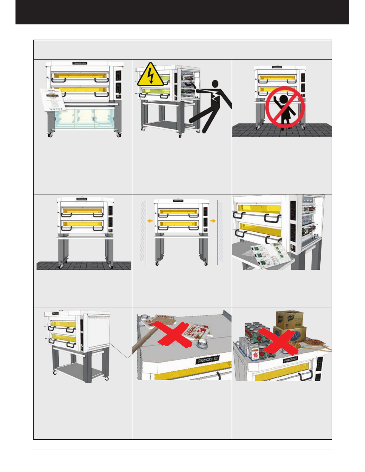
For ventilation reasons, position
the oven leaving 50mm (2”) bet-
ween the oven and any adjacent
wall
If possible, position the oven so that
its right-hand side can be accessed
easily in order to remove the right-
hand panel. This gives easy access
to the back of the control panel and
facilitates servicing of the oven.
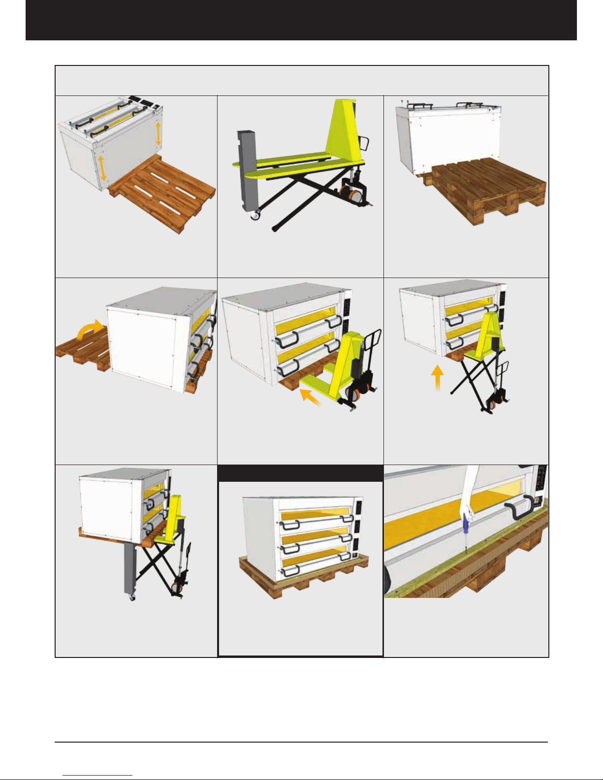
The oven is normally installed on
the legs supplied with it. It is also
important for the floor to be flat,
so that the oven is both horizontal
and stable.
Safety Precautions and Warnings
This appliances is not intended for
use by persons (including children)
with reduced physical, sensory or
mental capabilities, or lack of ex-
perience and knowledge, unless
they have been given supervisory
or instruction concerning use of the
appliance by a person responsible
for their safety.
High Risk of Electrocution!
Disconnect appliance from power
supply before opening.
To reduce the risk of electric shock,
DO NOT remove or open electrical
cover. Refer servicing to qualified
personnel.
To ensure safe operation, read
the following manual that contains
safety precautions and warnings
for your own safety
Safety and Warnings
The appliance must be installed with an
adequate restraining to limit the move-
ment of the appliance without transmit-
ting stress to the electrical conduit.The
restraining must be fastened in one of
the supports leg or spacers.
The appliance must be installed with a
flexible conduit.
DO NOT place any object blocking
the ventilation. this affects the
baking, oven performance and may
cause fire
The top of the oven is not consid-
ered as a food storage or as an food
preparation area.