PKP AZ260 User manual

PKP Prozessmesstechnik GmbH
Borsigstrasse 24
D-65205 Wiesbaden-Nordenstadt
Tel: 06122 / 7055 - 0
Fax: 06122 / 7055 – 50
Operating Instructions
AZ260

AZ260-eng Page 1
Instruction Manual
Model AZ260
Table of Contents
1. Safety Instructions
2. Product ID - Dimensions
3. Function Description
4. Installation – Battery Replacement
5. Programming
6. Technical Data
7. Spare Parts
1. Safety Instructions
This instrument has been manufactured in accordance with
the applicable state of the art and meets all safety
regulations as shipped from the factory. Installation and
startup must be performed by qualified electricians only!
Operate instrument only when properly installed!
If safe operation can no longer be ensured, disable the
instrument and secure it against unauthorized operation.
Prevent injury to people or damage to property due to
failure or malfunction of the equipment through additional
safety measures such as limit switches, protective
equipment, etc. .
Read the Instruction Manual carefully before startup!

AZ260-eng Page 2
2. Product Identification - Dimensions

AZ260-eng Page 3
3. Function Description
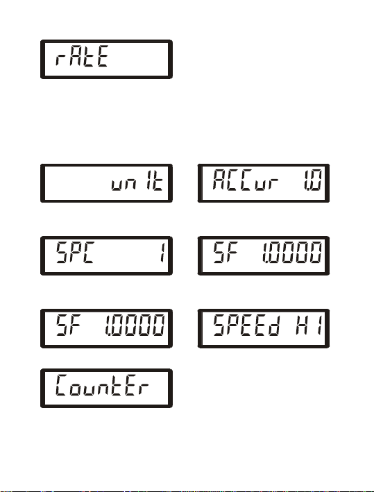
This instrument can be used as a rate meter and as a pulse
counter.
The instrument has been pre-programmed in the factory
and must be adapted to your process for both the rate
meter function and pulse counting (see Section 5 –
Programming).
The instrument is ready for operation when the
programming input is not wired. You can switch between
Rate meter and Pulse Counter displays using the S/E key
during operation at any time.
The instrument has two counting inputs.
Both inputs INA and INB (”Low“ or ”High“ active) are
designed for pulse sequences up to 30 Hz or up to 10 kHz
and you can they program any.
Note that you have to program both channels at the same
pulse sequence if the two inputs are working in parallel
connection with a common pulse source.
The backlighting is activated and load on the internal
battery is reduced by applying an external supply voltage of
24 VDC.
All stored data is lost when the battery is replaced. The
message "260_ xx" (xx for software version number)
appears after the new battery is installed. The instrument is
ready to operate after the S/E key is depressed, which
activates the factory programming.

AZ260-eng Page 4
Rate Meter
The rate meter operates by the principle of period length
measurement with ARS (Auto Range System).
You can adapt the display to your operation using the
programming sequence:
1. Input the physical unit of the rate meter (time basis)
2. Select accuracy
3. Set sensor pulse constant,
4. Program a suitable scaling factor and
5. Program the pulse sequency.
ARS helps minimize display process-related fluctuations
depending on the selected accuracy, rounds off the
displayed value, and sets the decimal point automatically.
Measurement starts with the active edge at the counter
input A. After the measurement time (1 sec) has elapsed,
the measurement is completed with the next active edge,
and the value is displayed in CHANNEL A. If no active edge
appears within the „time out“ period you have programmed,
the rate meter is reset to zero. At frequencies > 1 Hz the
average is calculated.
When the allowable count frequency is exceeded, the value
zero appears in the display; if the possible display range
(99999999) is exceeded, the display „E“ appears.
Display as delivered:
A
1
min
/
CHANNEL

AZ260-eng Page 5
Pulse Counter
The pulses entering at the input B are added and displayed
in CHANNEL B. You can scale the display using an
appropriate scaling factor. You can also set a fixed decimal
point and program the pulse counter so that you can reset it
either through the regular electrical reset on the back or
through the red Rkey on the front.
After pressing the S/E key:
B
CHANNEL
4. Installation – Battery replacement
After unpacking the instrument, remove the light-colored
frame from the back of the housing by simultaneously
bending both long sides of the frame slightly apart to
disengage them from the locking holes.
Then slide the housing through the cutout prepared in the
front panel, attach the frame onto the back of the housing,
slide it all the way against the back of the front panel, and
carefully attach it with the two side screws to the front
panel.
In this way, you can compensate for different front panel
thicknesses. Class IP 65 front protection is achieved
through the seal integrated in the housing.
See the wiring diagram below for the electric wiring.

AZ260-eng Page 6
1
2
3
4
5
6
0 V
Modell 260
IG
"LOW"-activ
Programming -
GND
Input INA
Input INB
Reset
Input
24 VDC Input
for Backlight
24 VDC "LOW"-activ
"HIGH"-activ
IG
"HIGH"-activ
Input INA+INB at "LOW"-activ Programming, Contacts not displayed
The battery is accessible from the back of the instrument.
There is a vertical notch under the middle of the nameplate.
Cut through the nameplate there.
Then slide out the two-part battery cover to one side along
the guide grooves, and replace the battery observing the
correct polarity. The instrument MUST BE connected to
24 VDC at this time, otherwise all settings will be lost!
5. Programming
The instrument can only be programmed by setting the
programming input PROG to 0 V.
Please note that this causes the pulse counter to be reset
internally.
After having set the programming input PROG to 0 V, the
following is displayed:

AZ260-eng Page 7
A
CHANNEL
This display identifies the rate meter (Channel A); it cannot
be changed.
By repeatedly pressing the S/E key, you can cycle through
the individual menu items. The following figures correspond
to the factory settings of the instrument:
A
1
min
/
CHANNEL
A
%
CHANNEL
Physical unit, Accuracy,
Channel A Channel A
A
CHANNEL
A
CHANNEL
Sensor pulse constant, Scaling factor,
Channel A Channel A
A
CHANNEL
A
CHANNEL
Time-out period, Channel A Count frequency, Channel A
B
CHANNEL
This display identifies the pulse counter (Channel B); it
cannot be changed.

AZ260-eng Page 8
B
CHANNEL
B
CHANNEL
Count frequency, Channel B Scaling factor, Channel B
B
CHANNEL
B
CHANNEL
Decimal point, Channel B Reset-key enabled,
Channel B
You can make changes within each menu point as follows:
1. Press the <R key:
The parameter to be changed is activated, i.e., it
begins to flash.
2. Press ^repeatedly if necessary:
Set the desired parameter.
3. Press S/E:
The parameter just set is confirmed and displayed
steadily.
4. Press S/E again:
You reach the next menu item.
See the possible settings allowed in each menu from the
following figures.
Flashing display elements are shown in a lighter color.

AZ260-eng Page 9
Physical unit, Channel A – Rate Meter
Selecting the physical unit:
A
1
min
/
CHANNEL
A
1h/
CHANNEL
Physical unit: 1/min Physical unit: 1/h
A
ls/
CHANNEL
A
l
min
/
CHANNEL
Physical unit: l/s Physical unit: l/min
A
lh/
CHANNEL
A
gals/
CHANNEL
Physical unit: l/h Physical unit: gal/s
A
gal
min
/
CHANNEL
A
galh/
CHANNEL
Physical unit: gal/min Physical unit: gal/h
A
1 s/
CHANNEL
Physical unit: 1/s
Accuracy, Channel A – Rate Meter
Setting measurement accuracy. See also page 13.

AZ260-eng Page 10
A
%
CHANNEL
A
%
CHANNEL
Accuracy 1% Accuracy 10%
A
%
CHANNEL
Accuracy 0.1%
Sensor Pulse Constant, Channel A – Rate Meter
You can set the pulse constant of the sensor in the range of
1 to 99999.
The sensor pulse constant provides the number of pulses
per unit.
Example: Set a sensor constant of 500 pulses per
revolution Press <R:
A
CHANNEL
A
CHANNEL
Press ^9 times: Press <R 2 times:
A
CHANNEL
A
CHANNEL
Press ^5 times: Press S/E:
A
CHANNEL
A
CHANNEL

AZ260-eng Page 11
Scaling factor, Channel A - Rate Meter
You may set the scaling factor (SF) in the range of 0.0001
to 99.9999 as explained for setting the pulse constant. The
scaling factor is used when converting one physical unit to
another (e.g., diameter to perimeter, liters to gallons).
Time-out Period, Channel A - Rate Meter
You can set the desired timeout period (time out) after
which the display is reset to zero if the operating frequency
is so low (or zero) that the measuring time would be
intolerably long.
The timeout period can be set in the range of 1s to 99s.
Example: Set timeout period to 10s
Press <R:
A
s
CHANNEL
A
s
CHANNEL
Press ^5 times: Press <R:
A
s
CHANNEL
A
s
CHANNEL
Press ^:Press S/E:
A
s
CHANNEL
A
s
CHANNEL
Count Frequency, Channel A –Rate Meter

AZ260-eng Page 12
A
CHANNEL
A
CHANNEL
maximum frequency 10 kHz maximum frequency 30 Hz
Count Frequency, Channel B –Pulse Counter
B
CHANNEL
B
CHANNEL
maximum frequency 10 kHz maximum frequency 30 Hz
Scaling Factor, Channel B – Pulse Counter
You can set the Scaling Factor in the range of 0.0001 to
99.9999.
Set the scaling factor as described under Scaling Factor,
Channel A.
Decimal point, Channel B – Pulse Counter
B
CHANNEL
B
CHANNEL
B
CHANNEL
B
CHANNEL
B
CHANNEL

AZ260-eng Page 13
Reset Key enabled, Channel B – Pulse Counter
B
CHANNEL
B
CHANNEL
TOTAL
Reset key enabled Reset key disabled
If you have not enabled the reset key, the string „TOTAL„ is
displayed.
Having completed the programming, disconnect the
programming input PROG from 0 V.
Please note that only the parameters confirmed with S/E
are accepted.
6. Technical Data
Displays
Special LC display with dimension line, 8 digits, 10 mm
digit height, pre-decimal point zero suppressed.
Display Capacity: Rate meter 99999999
Automatic decimal point
Pulse counter 99999999
Programmable decimal point
Accuracy
Period measurement accuracy:
Programmable to 0.1%, 1%, or 10% (corresponds to a
minimum resolution of 4, 3, or 2 digits, respectively).
Power Supply
internal lithium battery 3.6 V / 1.2 Ah
Average battery life 5 years
LED – Display backlighting

AZ260-eng Page 14
The LED display backlighting must be operated with
external voltage connected to 24 VDC and 0 V screw
terminals.
External Voltage: 24 VDC max. residual ripple 5%
absolute limits 19 to 30 VDC
Electromagnetic Compatibility (EMC)
Interference emission EN 55011 Group 1 Class B
Interference strength EN 50082-2
EN 61010-1 Measuring Insulation Voltage
100 Veff, Contamination Class 2, Surge Category III
DIN VDE 0411 Protection Class
Protection Class II
Electrical Connection
Terminal screw connection, P Phillips screws, size 1
max. lead section 2 x 1.5 mm²
min. lead section 2 x 0.2 mm²
IEC 529 Protection Class
IP 65 front
Temperature / Humidity range
Operating temperature range - 10°C to + 50°C
Storage temperature range - 20°C to + 70°C
Temperature / Humidity 90% relative humidity @ 38°C
IEC 68-2-6 Vibration Strength
Variable frequency range 10 to 500 Hz
0.35 mm or 5 g amplitude
10 Frequency cycles per axis
Dimensions
Frontal dimensions 36 mm x 72 mm
Total depth 38.5 mm

AZ260-eng Page 15
Fastening
Front panel mount via frame
Front panel thickness 0.8 mm to 6 mm
Front panel cutout DIN 4370033 +0.6 mm x 68 + 0.6 mm
Weight
approx. 95 g
Housing Material / Combustibility
PC plastic
Combustibiity V0 under UL Standard 94
Inputs
Input INA (Rate Meter) and Input INB (Pulse Counter)
Pulse shape any
Programmed as ”HIGH - SPEED“ input „High“ active
Signal level L<= 1 VDC H>= 5 VDC
Max. voltage amplitude ±30 VDC
Input resistance approx. 39 kOhm
Max. frequency (pulse duty factor 1:1) 10 kHz
min. pulse time 50 µs
min. pulse pause 50 µs
Active edge High/Low
Programmed as ”SLOW – SPEED“ input „Low“ - active
Signal level L<= 0 VDC H>= 5 VDC or open
Max. voltage amplitude ±30 VDC
Input resistance approx. 1 MOhm
Max. frequency (pulse duty factor 1:1) 30 Hz
min. pulse time 16 ms
min. pulse pause 16 ms
Active edge Low/High

AZ260-eng Page 16
Reset Input R (Pulse Counter)
Pulse shape any
Signal level L<= 0 VDC H>= 5 VDC or open
Max. voltage amplitude ±30 VDC
Input resistance approx. 1 MOhm
Static response “Low“ - active
min. pulse time 65 ms
Programming Input PROG
Static response „Low“ active
Input open Operating mode
Input connected to „0 V“ Programming mode
7. Spare Parts
Lithium battery SL-761/S Order No.: 1110761100

Accessories
AZ260
Digital Indicator
for Pulse Inputs
•compact design 36 x 72 mm
•for all sensors with pulse output
•8 digit LCD display for quantity / time
and total quantity
•easy programming
•battery supported and / or 24 VDC
Description:
The digital display unit type AZ260 is used to display process
signals of all sensors with pulse output. The device is micro-
processor controlled and therefore freely programmable. The
display of the quantity time unit can be switched over to the
total quantity by pressing a key. The input of K-factors and
scaling factors enables the convenient adaptation of the
AZ260 to all sensor parameters.
The devices operate independently of the mains by means of
a lithium battery. In addition, they can be operated externally
via a 24 VDC supply. In this case the back light is switched on
automatically.
Typical applications:
For display of flow rates, velocities, total quantities, speeds,
etc.
PKP Prozessmesstechnik GmbH
Borsigstr. 24 • D-65205 Wiesbaden
S +49 (0) 6122-7055-0 • T +49 (0) 6122 7055-50
[email protected] • www.pkp.de
20191017

Dimensions:
Housing: 72 x 36 x 38,5 mm (WxHxD)
Panel cut-out: 68 x 33 mm (WxH)
Attachment: tensioning frame, possible
panel thickness: 8...6 mm
Electrical Connection:
6 screw terminal connections
1 = reset 4 = counting input A (quantity time)
2 = 24 VDC input 5 = counting input B (total)
3 = ground 6 = programming input
Technical Data:
Display: 8-digit LCD, 11 mm height
speedometer: decimal point automatic
counter: decimal point programmable
Accuracy: programmable, 0,1 %, 1 %,
10 %, resolution corresponding to
min. 4-, 3- or 2-digits
Power supply: internal lithium battery, 3,6 V, 1,2 Ah,
LCD back light only with
external supply 19...30 VDC
Protection class: IP65 front-side
Ambient
temperature: -10 °C...+50 °C (operation)
-20 °C...+70 °C (storage)
Order Code:
rder number: AZ260. A
Digital Indicator
for pulse inputs
Inputs:
counting input A pulse form any
(speedometer): max. frequency 10 kHz,
max. pulse duration 50 µs,
L ≤ 1 VDC, H ≥ 5 VDC
counting input B pulse form any
(counter): when programming as HIGH-
SPEED input:
max. frequency 10 kHz
min. pulse duration 50 µs
L ≤ 1 VDC, H ≥ 5 VDC
when programming as LOW-
SPEED input:
max. frequency 30 Hz
min. pulse duration 16 ms
L ≤ 0 VDC, H ≥ 5 VDC
or open
Programming input:
input open: operating mode
input to ground: programming mode
Side View:
PKP Prozessmesstechnik GmbH
Borsigstr. 24 • D-65205 Wiesbaden
S +49 (0) 6122-7055-0 • T +49 (0) 6122 7055-50
[email protected] • www.pkp.de
Accessories
Table of contents
Popular Monitor manuals by other brands

HP
HP w19 - Widescreen LCD Monitor Service manual

Sony
Sony Trinitoron CPD-G220 Service manual

Pioneer
Pioneer PDP-436RXE operating instructions

Iiyama
Iiyama ProLite T1531SR specification

Elvox
Elvox wide TOUCH 7311 operating instructions

Austin Hughes Electronics
Austin Hughes Electronics CyberView RP-1020QD brochure