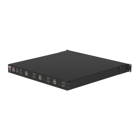
Planar Matrix Video Extender Quick start guide

020-1048-00A 1
The Matrix video extender box allows you to extend the distance between the
Quad controller and LCD modules by an additional 100 feet. Additional
extender boxes can be used in series to extend the minimum distance of 500
feet. These instructions explain how to hook up the video extender box and
how to set the EQ for each LCD module. Below is a basic diagram that shows
how the extender box should be hooked up.
Note: The COMM cables do not run through the extender box, as it is not necessary to
boost them along the way.
IR sensor
VIDEO
COMM
VIDEO
COMM
VIDEO
COMM
VIDEO
COMM
Quad Module
IR
VIDEO 1
COMM 1
VIDEO 2
COMM 2
VIDEO 3
COMM 3
VIDEO 4
COMM 4
Extender Box
LCD 1
LCD 2
LCD 3
LCD 4
IR Out IR In
1
2
3
4
1
2
3
4
LCD
Out
LCD
In
Connecting the Matrix
Video Extender Box

Connecting the Matrix Video Extender Box
2
Setting Up Your Wall Using One Extender Box
If you have not already done so, it is recommended that you label all of your
cables before running them. Use the dispenser of cable labels you received
with your Matrix Video Wall.
1Plug one end of the DC wall power adapter into the AC outlet. Plug the
other end into the 12W DC power connector on the OUTPUT side of the
extender box. If there is power coming into the extender box, the POWER
LED on the INPUT side should be green.
2Plug one end of the male to male IR cable into the IR connector of the
master (A) Quad controller module. Plug the other end into the IR Out
connector on the INPUT side of the extender box.

Connecting the Matrix Video Extender Box
3
3Plug the male side of one male to female IR cable into the IR In connector
on the OUTPUT side of the extender box.
4Plug the female end of the cable into the male end of the IR sensor that
came with your Matrix Video Wall. If the Quad controller module is
powered on, you should now see a green IR LED on both sides.
Note: For larger walls greater than four displays, the IR sensor is only hooked up to the
extender box associated with Quad controller module A.
Plug this end into
the IR connector of
the OUTPUT side
of extender box.
Plug this end into the
male end of the IR
sensor cable.

Connecting the Matrix Video Extender Box
4
5Plug one end of the data cable into the LCD1 VIDEO connector of the
Quad controller module.
6Plug the other end of the data cable into LCD 1 on the INPUT side of the
extender box. If the Quad controller module is powered on and the
extender box is on, the green LED should light.
7Take the second data cable and plug it into LCD 1 of the OUTPUT side of
the extender box.
8Plug the other side of the data cable into the VIDEO connector of LCD 1.
9Depending on the cable length that is running between the extender box
and the LCD, you might see vertical lines or noise on the LCD. If you do,
you will need to adjust the EQ on the extender box, as well as on the LCD
itself through the on-screen menus.
LCD

Connecting the Matrix Video Extender Box
5
10 You will first want to set the EQ on the extender box. Using the address
selector tool that came with your Matrix LCD video wall, manually adjust
the equalization of each LCD. For most cable lengths, set it in the range of
3-5. See the table below for settings of different cable lengths.
Table 1: EQ Settings Per Cable Length
Cable Length EQ Setting
20-30 feet 0
50 feet 3
100 feet 5

Connecting the Matrix Video Extender Box
6
11 If you still see noise or vertical lines on the LCD, you will need to adjust the
EQ on the LCD itself through the on-screen menus. Press the MISC button
once on the remote to pull up the MISCELLANEOUS OPTIONS menu. In
order to set the EQ on an individual LCD, you will need to move the
“target” to the correct display ID of the LCD you want to adjust. For
example, B1, B2, etc. Press the < or > buttons on the remote until you see a
green box around the display ID.
12 Using the -/+ buttons on the remote, move the CABLE EQUALIZATION line
up or down until you do not see any vertical lines on the LCD. The CABLE
EQUALIZATION line is shipped in the nominal position of 4, so you may only
need to make minor adjustments between the range of 3-5. In most cases,
4 will be sufficient.
13 When you are finished, close the on-screen menus.
14 Repeat steps 5-12 for each LCD in your video wall.
ON
** PICTURE
WALL
SOURCE
BALANCE
MISC
MONITOR
MENU PREV ENTER
- +
OFF SAVE
Clarity Matrix
TOP
Press one of these until you
see a green box around the
display ID of the LCD you
want to adjust.
Miscellaneous
Cable Equalization 1
*
*** Copy Settings to All Displays

Connecting the Matrix Video Extender Box
7
Setting Up Your Wall Using Multiple Extender Boxes
In some cases, if the total distance is greater than 200 feet, additional
extender boxes can be hooked up in series. Each series module will extend
the distance by 100 feet. Four boxes in series will provide a minimum drive
distance of 500 feet. Greater distances may be achieved, but it is up to the
installer to test the performance with the cabling they plan to use in the
installation, since cabling selection can affect the distance. Each extender box
boosts the video data enough to travel up to 100 feet per box.
We suggest that you number each extender box with a marker by drawing in
the white box on the OUTPUT side of the extender box.
See the next page for a basic diagram that shows how multiple extender
boxes should be hooked up.

Connecting the Matrix Video Extender Box
8
Note: The COMM cables do not run through the extender box, as it is not necessary to
boost them along the way.
The equalization settings are linked to the INPUT side of the extender box. For
different cable lengths, see "EQ Settings Per Cable Length" on page 5.
Quad Module 1
IR
VIDEO 1
COMM 1
VIDEO 2
COMM 2
VIDEO 3
COMM 3
VIDEO 4
COMM 4
RS485
Extender Box
IR Out IR In
1
2
3
4
LCD In LCD Out
1
2
3
4
Extender Box
IR Out IR In
1
2
3
4
LCD In LCD Out
1
2
3
4
Video Wall
VIDEO
COMM
VIDEO
COMM
VIDEO
COMM
LCD 1
LCD 2
LCD 3
LCD 4
IR sensor
VIDEO
COMM
Quad Module 2
IR
VIDEO 1
COMM 1
VIDEO 2
COMM 2
VIDEO 3
COMM 3
VIDEO 4
COMM 4
RS485
Extender Box
IR Out IR In
1
2
3
4
LCD In LCD Out
1
2
3
4
Extender Box
IR Out IR In
1
2
3
4
LCD In LCD Out
1
2
3
4
Video Wall
VIDEO
COMM
VIDEO
COMM
VIDEO
COMM
LCD 1
LCD 2
LCD 3
LCD 4
VIDEO
COMM

Connecting the Matrix Video Extender Box
9
Declaration of Conformity
We, Planar Systems, Inc., located at
1195 NW Compton Drive
Beaverton, OR 97006-1992
European Representative:
Planar Systems, Inc.
Olarinluoma 9 P.O. Box 46
Fin-02201 Espoo, Finland
Declare, under our sole responsibility, that Planar Systems, Inc.’s product:
Name: Matrix Video Extender
Brand: Planar
Model: Matrix Video Extender
is in conformity with the essential requirements of the EMC Directive 2004/108/EC and the
Low Voltage Directive 2006/95/EC.
The following standards have been applied:
EMMISSIONS EN 55022:2006, Class A
EN61000-3-2:2006
EN61000-3-3:1995+A1:2001 +A2:2005
IMMUNITY EN 55024:1998+A1:2001+A2:2003
IEC 61000-4-2:2008
IEC 61000-4-3:2006+A1:2007
IEC 61000-4-4:2004
IEC 61000-4-5:2005
IEC 61000-4-6:2008
IEC 61000-4-8:2001
IEC 61000-4-11:2004
SAFETY EN60350-1:2001
(LVD applies to External Power Supply)
Table of contents
Other Planar Extender manuals
Popular Extender manuals by other brands

PULSEEIGHT
PULSEEIGHT P8-AE-CAT-EXSET Quick setup guide

Cable-Tronix
Cable-Tronix CT-COMP-EXT installation manual

Tripp Lite
Tripp Lite B130-101A-WP-1 Quick manual

ImmersionRC
ImmersionRC TNR Tramp HV Preliminary Operator's Manual

Black Box
Black Box ServSwitch ACS253A-CT Specifications

Tripp Lite
Tripp Lite B127A-1A1-BDBD owner's manual