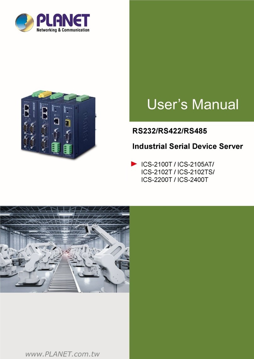
Planet Networking & Communication Serial Device Server Series User manual

User’s Manual of IGS-2x00T Serial Device Server Series
1
Industrial RS232/RS422/RS485
Serial Device Server Series
ICS-2200T/ICS-2400T

User’s Manual of IGS-2x00T Serial Device Server Series
2
Trademarks
Copyright © PLANET Technology Corp. 2019.
Contents are subject to revision without prior notice.
PLANET is a registered trademark of PLANET Technology Corp. All other trademarks belong to their respective owners.
Disclaimer
PLANET Technology does not warrant that the hardware will work properly in all environments and applications, and makes no
warranty and representation, either implied or expressed, with respect to the quality, performance, merchantability, or fitness for
a particular purpose. PLANET has made every effort to ensure that this User's Manual is accurate; PLANET disclaims liability
for any inaccuracies or omissions that may have occurred.
Information in this User's Manual is subject to change without notice and does not represent a commitment on the part of
PLANET. PLANET assumes no responsibility for any inaccuracies that may be contained in this User's Manual. PLANET makes
no commitment to update or keep current the information in this User's Manual, and reserves the right to make improvements to
this User's Manual and/or to the products described in this User's Manual, at any time without notice.
If you find information in this manual that is incorrect, misleading, or incomplete, we would appreciate your comments and
suggestions.
FCC Warning
This equipment has been tested and found to comply with the limits for a Class A digital device, pursuant to Part 15 of the FCC
Rules. These limits are designed to provide reasonable protection against harmful interference when the equipment is operated
in a commercial environment. This equipment generates, uses, and can radiate radio frequency energy and, if not installed and
used in accordance with the Instruction manual, may cause harmful interference to radio communications. Operation of this
equipment in a residential area is likely to cause harmful interference in which case the user will be required to correct the
interference at his own expense.
CE Mark Warning
This is a ClassA product. In a domestic environment, this product may cause radio interference, in which case the user may be
required to take adequate measures.
Energy Saving Note of the Device
This power required device does not support Standby mode operation. For energy saving, please remove the power cable to
disconnect the device from the power circuit. In view of saving the energy and reducing the unnecessary power consumption, it
is strongly suggested to remove the power connection for the device if this device is not intended to be active.
WEEE Warning
To avoid the potential effects on the environment and human health as a result of the presence of
hazardous substances in electrical and electronic equipment, end users of electrical and electronic
equipment should understand the meaning of the crossed-out wheeled bin symbol. Do not dispose of
WEEE as unsorted municipal waste and have to collect such WEEE separately.
Revision
PLANET ICS-2200T / ICS-2400T User's Manual
Model: ICS-2200T / ICS-2400T
Revision: 1.0 (Nov, 2019)
Part No: EM- ICS-2200T_ICS-2400T_v1.0

User’s Manual of IGS-2x00T Serial Device Server Series
3
TABLE OF CONTENTS
1. INTRODUCTION .................................................................................................................... 5
1.1 Packet Contents.............................................................................................................................................5
1.2 Product Description........................................................................................................................................6
1.3 How to Use This Manual ................................................................................................................................9
1.4 Product Features..........................................................................................................................................10
1.5 Product Specifications..................................................................................................................................12
2. INSTALLATION ................................................................................................................... 15
2.1 Hardware Description...................................................................................................................................15
2.1.1 Front Panel..........................................................................................................................................................15
2.1.2 Front Panel..........................................................................................................................................................16
2.1.3 LED Indications ...................................................................................................................................................17
2.1.4 Wiring the Power Inputs.......................................................................................................................................18
2.1.5 Serial Port Pin Define..........................................................................................................................................19
2.2 Installing the Industrial Serial Server............................................................................................................20
2.2.1 Installation Steps.................................................................................................................................................20
2.2.2 DIN-Rail Mounting...............................................................................................................................................21
2.2.3 Wall Mount Plate Mounting..................................................................................................................................23
3. INDUSTRIAL SERIAL SERVER MANAGEMENT ............................................................... 24
3.1 Requirements...............................................................................................................................................24
3.2 Web Management........................................................................................................................................25
3.2.1 Logging in to the Industrial Serial Server.............................................................................................................25
3.3 Remote Management...................................................................................................................................27
3.4 PLANET Smart Discovery Utility..................................................................................................................28
4. WEB CONFIGURATION ...................................................................................................... 30
4.1 Main Web Page............................................................................................................................................32
4.2 System..........................................................................................................................................................33
4.2.1 System.................................................................................................................................................................33
4.2.2 Port......................................................................................................................................................................35
4.2.3 Device..................................................................................................................................................................36
4.2.4 Time.....................................................................................................................................................................36
4.2.5 Console ...............................................................................................................................................................37
4.2.6 Fault Alarm ..........................................................................................................................................................37
4.2.7 Digital Input/Output..............................................................................................................................................38

User’s Manual of IGS-2x00T Serial Device Server Series
4
4.3 Accessible IP................................................................................................................................................39
4.4 Network ........................................................................................................................................................40
4.5 Port Config....................................................................................................................................................41
4.5.1 Serial setup..........................................................................................................................................................42
4.5.2 Operation mode...................................................................................................................................................43
4.5.2.1 Disable mode ............................................................................................................................................43
4.5.2.2 Remote Pair Master/Slave mode...............................................................................................................44
4.5.2.3 RF2217 mode............................................................................................................................................46
4.5.2.4 Serial Telnet mode.....................................................................................................................................47
4.5.2.5 TCP Server mode......................................................................................................................................49
4.5.2.5 TCP Client mode.......................................................................................................................................52
4.5.2.6 UDP mode.................................................................................................................................................54
4.5.2.7 Virtual COM mode.....................................................................................................................................56
4.6 SNMP Setup.................................................................................................................................................59
4.7 Maintenance.................................................................................................................................................60
4.7.1 Change Password...............................................................................................................................................60
4.7.2 Load Default........................................................................................................................................................60
4.7.3 Firmware Update.................................................................................................................................................61
4.8 Save and Restart..........................................................................................................................................62
5. SOFTWARE VCOM UTILITY ............................................................................................... 63
5.1 Installing the VCOM Utility............................................................................................................................63
5.2 Search Devices ............................................................................................................................................65
5.3 Virtual COM..................................................................................................................................................66

User’s Manual of IGS-2x00T Serial Device Server Series
5
1. INTRODUCTION
Thank you for purchasing PLANET ICS-2200T/ICS-2400T Industrial Multi-port Serial Device Server. “Industrial Serial Server” is
used as an alternative name in this Quick Installation Guide.
ICS-2200T Industrial 2-Port RS232/RS422/RS485 Serial Device Server
ICS-2400T Industrial 4-Port RS232/RS422/RS485 Serial Device Server
“Industrial Serial Server” mentioned in this Guide refers to the ICS-2200T/ICS-2400T.
1.1 Packet Contents
Open the box of the Industrial Serial Server and carefully unpack it. The box should contain the following items:
The Industrial Serial Server x 1
Quick Installation Guide x 1
Wall Mounting Kit x 1
Dust Cap x 2
If any of these are missing or damaged, please contact your dealer immediately; if possible, retain the carton including the
original packing material, and use them again to repack the product in case there is a need to return it to us for repair.

User’s Manual of IGS-2x00T Serial Device Server Series
6
1.2 Product Description
Cost-effective Solution for RS232/422/485 Serial-to-Industrial Ethernet Application
PLANET ICS-2x00T Serial Device Server series is specially designed to convert RS232, RS422 or RS485 serial communication
to Industrial Fast Ethernet networking so as to extend the network distance efficiently and inexpensively. There are two
10/100BASE-TX RJ45 ports available in the ICS-2x00T series for your network needs. The ICS-2x00T series is a time-saving
and cost-effective solution for users and system integrators to quickly transform their serial devices into the Ethernet network
with no need of replacing the existing serial devices and software system.
Remote Management
As the ICS-2x00T series provides an easy serial-to-Ethernet connectivity and connection to a TCP/IP network, the remote
network system can thus be managed efficiently via its Web, Telnet and VCOM management interfaces. It supports both
application and serial operation modes for alarm or IP address connection, which saves the network administrator’s time in
detecting and locating network problems without visual inspection of the cabling and devices. Multiple connection options are
available for large networking environment as well.

User’s Manual of IGS-2x00T Serial Device Server Series
7
Stable Performance under Difficult Environments
The ICS-2x00T series provides a high level of immunity against electromagnetic interference and heavy electrical surges which
are usually found on plant floors or in curbside traffic control cabinets. Its operating temperature ranging from -40 to 75 degrees
C allows the ICS-2x00T series to be placed in almost any difficult environment.
The ICS-2x00T series with the compact IP30-/IP40-rated metal case allows either DIN-rail or wall mounting for efficient use of
cabinet space. The ICS-2x00T series also provides an integrated power supply source with a wide range of voltages (12 to 48V
DC) ideally suitable for worldwide operation with high availability applications requiring dual or backup power inputs.
Dual Power Input for High Availability Network System
The ICS-2x00T series features a strong dual power input system with wide-ranging voltages (12V~48V DC) incorporated into
customer’s automation network to enhance system reliability and uptime. In the example below, when Power Supply 1 fails to
work, the hardware failover function will be activated automatically to keep powering the ICS-2x00T series via Power Supply 2
without any break of operation.

User’s Manual of IGS-2x00T Serial Device Server Series
8
Effective Alarm Alert for Better Protection
The ICS-2x00T series comes with a Fault Alarm feature which can alert the users when there is something wrong with the Serial
Device Server. With this ideal feature, the users would not have to waste time finding where the problem is. It will help to save
time and human resource. The ICS-2x00T series provides event alert function to help to diagnose the abnormal device owing to
whether or not there is a break of the network connection, or the rebooting response.
Digital Input and Digital Output for External Alarm
With digital input and digital output on its front panel, an external alarm can help users via the digital input to detect and log
external device status (such as door intrusion detector), and then immediately send an event alarm to the administrator. The
digital output can be used to alarm the administrator if the ICS-2400T serial port shows connection failure or power failure.

User’s Manual of IGS-2x00T Serial Device Server Series
9
1.3 How to Use This Manual
This User’s Manual is structured as follows:
Section 2, INSTALLATION
It explains the functions of the ICS-2X00T and how to physically install the ICS-2X00T.
Section 3, INDUSTRIAL SERIAL SERVER MANAGEMENT
The chapter explains how to manage the ICS-2X00T in different ways.
Section 4, WEB CONFIGURATION
It describes how to configure by web interface.
Section 5, SOFTWARE VCOM UTILITY
It describes how to use software VCOM in the Virtual COM mode.

User’s Manual of IGS-2x00T Serial Device Server Series
10
1.4 Product Features
Serial Interface
Two/four DB9 interfaces support RS232, 2-wire RS485, 4-wire RS485 and RS422 operations
Asynchronous serial data rates up to 921600bps
Data mode including VCOM, RFC2217, TCP Server, TCP Client, UDP, Remote Pair and Serial Telnet modes
Ethernet Interface
Two 10/100BASE-TX RJ45 interfaces with auto MDI/MDI-X function
Ethernet ports support Ethernet switch or cascading operation for easy wiring
Management
IPv4 and IPv6 dual stack management
Remote Management Interfaces
- IP-based Web management
- Telnet console management
- Windows-based VCOM utility supports searching, monitoring and configuration setting
IP NTP (Network Time Protocol) and DNS management
Standard TCP/IP interface and versatile operation modes
Software Protocol supports ARP, ICMP, TCP/IP, UDP, HTTP server, DHCP client, Telnet server/client
Serial Operation mode selected via management interface
Pair Connection mode for connecting two serial devices over a network
Allows a maximum of 4 hosts to be accessed in TCP client mode
Firmware upgrade via HTTP protocol
Accessible IP security control to prevent illegal users
Event notification
- Remote syslog server
- SNMP trap
- Built-in buzzer
- Relay output alarm
- Digital output (ICS-2400T only)
DHCP client for IP address assignment
PLANET Smart Discovery utility automatically finds the client devices on the network
Industrial Case and Installation
IP30 metal case (ICS-2200T only)
IP40 metal case (ICS-2400T only)
DIN-rail and wall-mount designs
Redundant power design
−12 to 48V DC, redundant power with reverse polarity protection

User’s Manual of IGS-2x00T Serial Device Server Series
11
Supports 6000 VDC Ethernet ESD protection
-40 to 75 degrees C operating temperature
Free fall, shock-proof and vibration-proof for industries
Supports extensive LED indicators for network diagnosis
Reset button for resetting to factory default
Digital Input and Digital Output (ICS-2400T only)
2 digital inputs (DI)
2 digital outputs (DO)
Integrate sensors into auto alarm system
Transfer alarm to IP network via email and SNMP trap

User’s Manual of IGS-2x00T Serial Device Server Series
12
1.5 Product Specifications
Product ICS-2200T ICS-2400T
Serial Interface
Serial Ports 2 x DB9 male 4 x DB9 male
Serial Standards
RS232/RS422/4-wire RS485/2-wire RS485
Baud Rate (Data Rate) 50bps to 921Kbps
Data Bits 5, 6, 7, 8
Parity Type 1, 1.5, 2
Stop Bit
Odd, Even, None, Space, Mark
Flow Control RTS/CTS and DTR/DSR (RS232 only)
XON/XOFF
Signals
RS232: TxD, RxD, RTS, CTS, DTR, DSR, DCD, GND
RS422: Tx+, Tx-, Rx+, Rx-, GND
4-wire RS485: Tx+, Tx-, Rx+, Rx-, GND
2-wire RS485: Data A (+), Data B (-), GND
Pin Assignment
Serial Line Protection
2KV isolation protection
1KV (level 2) surge protection
15KV ESD protection
Ethernet Interface
Ethernet Ports 2 x RJ45 2 x RJ45
Standard 10/100BASE-TX
Distance 100m
Switch Architecture
Store-and-Forward-
Address Table 1K
ESD Protection 6KV
Surge Protection 2KV
Hardware
Installation DIN-rail kit and wall-mount ear
Enclosure IP 30 metal IP40 metal
Dimensions (W x D x H) 32 x 97 x 135 mm 56 x 87 x 135 mm
Weight 477 g 625 g
LED Indicators System: Power 1, Power 2, Fault, SYS
TP Port: Link/Active
System: Power 1, Power 2, Fault, SYS,
I/O

User’s Manual of IGS-2x00T Serial Device Server Series
13
Serial Port: Tx and Rx TP Port: Link/Active
Serial Port: Tx and Rx
Power Requirements 12~48V DC, redundant power with reverse polarity protection
Power Consumption
Full Loading
12VDC: 0.326A (3.8 watts)
24VDC: 0.176A (4.2 watts)
48VDC: 0.114A (5.4 watts)
Full Loading
12VDC: 0.419A (5.1 watts)
24VDC: 0.227A (5.4 watts)
48VDC: 0.136A (6.5 watts)
Connector Removable 6-pin terminal block for power input
Pin 1/2 for Power 1, Pin 3/4 for fault alarm, Pin 5/6 for Power 2
DI and DO N/A
2 digital inputs:
Level 0: -24V~2.1V (±0.1V)
Level 1: 2.1V~24V (±0.1V)
Input Load to 24V DC, 10mAmax.
2 digital outputs:
Open collector to 24V DC, 100mAmax.
Alarm Provides one relay output for power failure
Alarm relay current carry ability: 1A@ DC 24V
Reset Button < 5 sec: System reboot
> 5 sec: Factory default
Management
Management Interfaces
Web management
Telnet Console management
Windows-based VCOM Utility management
PLANET Smart Discovery Utility
IP Version IPv4 and IPv6
Operation Mode
TCP Server
TCP Client
UDP
Virtual COM
RFC2217
Telnet Server
Pair Connection – Remote (Slave)
Pair Connection – Local (Master)
Virtual COM Utility
Platform Supports
Windows-based only:
Windows XP
Windows Server 2003
Windows 7
Windows Server 2008
Windows 8 (Must install the latest version of WinPcap)
Windows Server 2012 (Must install the latest version of WinPcap)
Windows 10
Alert Built-in buzzer and RTC
Security Allows maximum 4 accessible IP address hosts/ranges

User’s Manual of IGS-2x00T Serial Device Server Series
14
SNMP MIBs RFC1213 MIB-II
RFC1317 RS232-like OIDs
Standards Conformances
Regulatory Compliance FCC Part 15 Class A,
CE Certification Class A
Stability Testing
IEC60068-2-32 (Free fall)
IEC60068-2-27 (Shock)
IEC60068-2-6 (Vibration)
Standards
IEEE 802.3 10BASE-T
IEEE 802.3u 100BASE-TX
IEEE 802.3x flow control and back pressure
RFC 768 UDP
RFC 793 TFTP
RFC 791 IP
RFC 792 ICMP
RFC 854 Telnet
RFC 958 NTP
RFC 1591 DNS (client only)
RFC 1908 SNMPv2c
RFC 2068 HTTP
RFC 2131 DHCP Client
RFC 2732 Format for Literal IPv6 Addresses in URL's
RFC 3315 DHCPv6 Client
RFC 3513 IPv6 Addressing Architecture
RFC 3596 DNSv6
RFC 4443 ICMPv6
EIA/TIA RS232/422/485
Regulatory Approval RoHS
Environment
Operating Temperature
-40 ~ 75 degrees C
Storage Temperature -40 ~ 85 degrees C
Humidity 5 ~ 95% (non-condensing)

User’s Manual of IGS-2x00T Serial Device Server Series
15
2. INSTALLATION
This section describes the hardware features and installation of the Industrial Serial Servers' components on the desktop or rack.
For easier management and control of the Industrial Serial Servers, familiarize yourself with its display indicators, and ports.
Front panel illustrations in this chapter display the LED indicators. Before connecting any network device to the Industrial Serial
Servers, please read this chapter completely.
2.1 Hardware Description
2.1.1 Front Panel
The front panels of the Industrial Serial Servers are shown in Figure 2-1-1.
Front Panel
ICS-2200T ICS-2400T
Figure 2-1-1: Front Panels of Industrial Serial Servers

User’s Manual of IGS-2x00T Serial Device Server Series
16
■Fast TP interface
10/100BASE-TX copper, RJ45 twisted-pair: Up to 100 meters.
■Serial Interface
Supports RS-232, RS-422, RS-485 2-wire and RS485 4-wire.
2.1.2 Front Panel
The bottom panels of the Industrial Serial Servers are shown in Figure 2-1-2.
Bottom Panel
ICS-2200T ICS-2400T
Figure 2-1-2: Bottom Panels of Industrial Serial Servers
■Reset button
On the bottom panel, the reset button is designed for rebooting the system and stopping the buzzer. The following is the
summary table of the reset button functions:
Reset Button Reset Button Pressed and
Released Function
System Reset
< 5 sec: System reboot Reboot the Industrial Serial Server
> 5 sec: Factory default
Reset the Industrial Serial Server to Factory
Default configuration. The Industrial Serial
Server will then reboot and load the default
settings as shown below:
。Default Username: admin
。Default Password: admin
。Default IP address: 192.168.0.100
。Subnet mask: 255.255.255.0
。Default Gateway:
192.168.0.254
Buzzer Reset >1 sec Stop the buzzer

User’s Manual of IGS-2x00T Serial Device Server Series
17
2.1.3 LED Indications
The front panel LEDs indicate instant status of power and system status, fan status, port links / PoE-in-use and data activity;
they help monitor and troubleshoot when needed.
LED indication
■System
LED
Color
Function
PWR 1 Green Lights Power 1 is activated.
PWR 2 Green Lights Power 2 is activated.
Fault Red Lights Indicates either Power 1 or Power 2 has no power.
SYS Green Blinks System is booting.
Lights System is ready.
I/O Red Blinks Digital I/O event is triggered.
■10/100BASE-TX Port
LED Color Function
LNK/
ACT
Green
Lights Indicates that the port is linked up.
Blinks Indicates
that the switch is actively sending or receiving data over
that port.
■Serial Ports (P1~P4)
LED Color Function
TX Green Blinks Serial port is transmitting data.
RX Amber Blinks Serial port is receiving data.

User’s Manual of IGS-2x00T Serial Device Server Series
18
2.1.4 Wiring the Power Inputs
The upper panel of the Industrial Serial Server indicates a DC inlet power socket and consists of one terminal block connector
within 6 contacts. Please follow the steps below to insert the power wire.
1. Insert positive/negative DC power wires into Contacts 1 and 2 for Power 1, or Contacts 5 and 6 for Power 2. Figure 2-1-3
and 2-1-4 show PWR1 and PWR2 of the Industrial Serial Server.
ICS-2200T: 12~48V DC
Figure 2-1-3 ICS-2200T Upper Panel
ICS-2400T: 12~48V DC
Figure 2-1-4 ICS-2400T Upper Panel
2. Tighten the wire-clamp screws for preventing the wires from loosening.
1 2 3 4 5 6
V1+ V1- V2+ V2-
Power 1 Fault Power 2
Figure 3-3 PWR1 & PWR2 pin of terminal block.

User’s Manual of IGS-2x00T Serial Device Server Series
19
The wire gauge for the terminal block should be in the range
from 12 to 24 AWG.
2.1.5 Serial Port Pin Define

User’s Manual of IGS-2x00T Serial Device Server Series
20
2.2 Installing the Industrial Serial Server
This section describes how to install your Industrial Serial Server and make connections to the Industrial Serial Server. Please
read the following section and perform the procedure in the order being presented. To install your Industrial Serial Server on a
desktop or rack, simply complete the following steps.
2.2.1 Installation Steps
1. Unpack the Industrial Serial Server
2. Check if the DIN-rail bracket is screwed on the Industrial Serial Server or not. If the DIN-rail bracket is not screwed on
the Industrial Serial Server, please refer to DIN-rail Mounting section for DIN-rail installation. If users want to
wall-mount the Industrial Serial Server, please refer to the Wall Mount Plate Mounting section for wall-mount plate
installation.
3. To hang the Industrial Serial Server on the DIN-rail track or wall.
4. Power on the Industrial Serial Server. Please refer to the Wiring the Power Inputs section for knowing the information
about how to wire the power. The power LED on the Industrial Serial Server will light up. Please refer to the LED
Indicators section for indication of LED lights.
5. Prepare the twisted-pair, straight-through Category 5 cable for Ethernet connection.
6. Insert one side of RJ45 cable (category 5) into the Industrial Serial Server Ethernet port (RJ45 port) while the other
side to the network device’s Ethernet port (RJ45 port), e.g., Switch PC or Server. The UTP port (RJ45) LED on the
Industrial Serial Server will light up when the cable is connected with the network device. Please refer to the LED
Indicators section for LED light indication.
Make sure that the connected network devices support MDI/MDI-X. If it does not support,
use the crossover Category 5 cable.
7. When all connections are set and all LED lights show normal, the installation is completed.
This manual suits for next models
2
Table of contents
Other Planet Networking & Communication Server manuals

Planet Networking & Communication
Planet Networking & Communication ICS-2100T User manual

Planet Networking & Communication
Planet Networking & Communication IAS-2400 User manual

Planet Networking & Communication
Planet Networking & Communication IVS-2120 User manual

Planet Networking & Communication
Planet Networking & Communication ICS-110 User manual

Planet Networking & Communication
Planet Networking & Communication ICS-2Serie User manual