16 Channel Digital Video Recorder User
s Manual
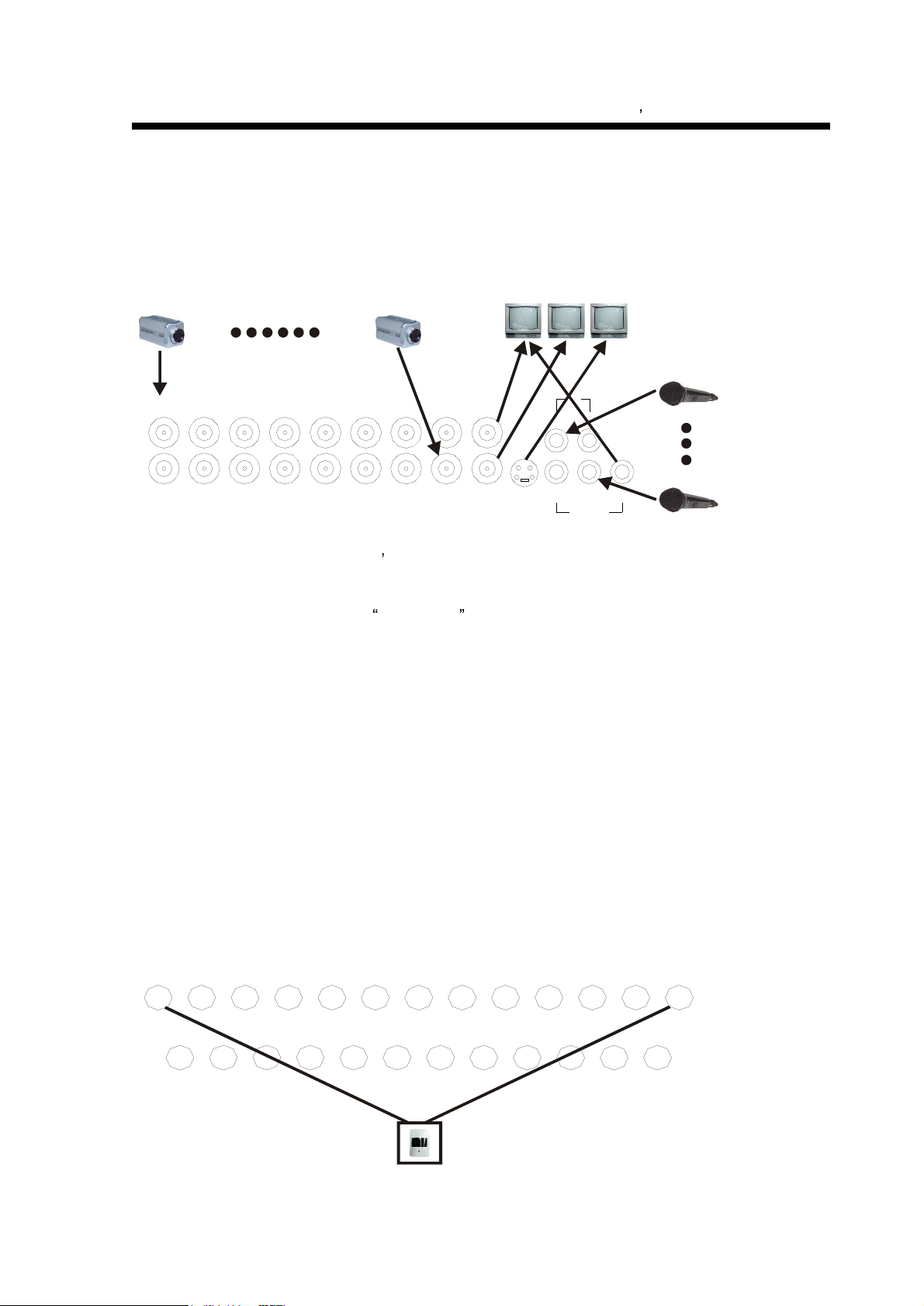
7
according to the time set in auto sequence set menu, you can set the dwell time of each channel.
Push this button to quit this mode. If not in shift mode, push this button to see big picture of
channel 1. While inputting numbers, this button is used as number key of
1 .
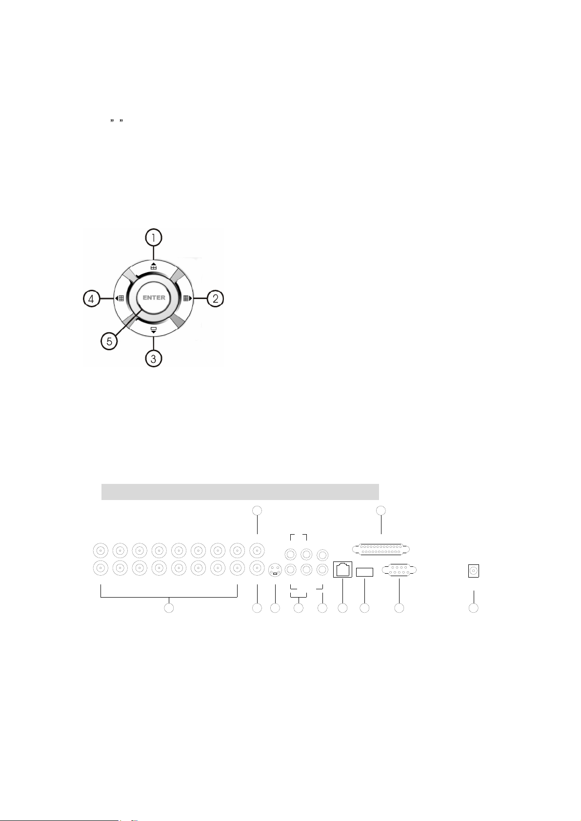
2. Zoom/2:
Zoom key, in shift mode, push this button, the DVR will be in zoom mode, please refer
to zoom operation in user guideline for details, push zoom button again to cancel zoom
operation
.
If not in shift mode, push this button to see big picture
of channel 2. While inputting numbers, this
button is used as number key of
2 .
3.
USB/3:
USB key, in shift mode, push this button, the DVR will start USB backup, please refer to
USB backup operation in user guideline for details, push USB button again to
cancel
USB backup. If not in shift mode, push this button to see big picture of channel 3,
while
inputting
numbers, this button is used as number key of
3 .
4.
Display/4:
Display key, in shift mode, push this button to display current information on the
screen, push again this to clear the information display. If not in shift mode, push this button to
see big picture of channel 4. While inputting numbers, this button is used as number key of
4
5. Freeze/5: Freeze key, in shift mode, push this button, the DVR will be in freeze mode, please
refer to freeze operation in user guideline for details, re
-
push this button to quit freeze mode, If not
in shift mode, push this button to see big picture of channel 5. While inputting numbers, this
button is used as
number key of
5 .
6.WM/10+:
Watermark button, In shift mode, if the DVR is playing video, you can push this button
to see the watermark of the picture, if the video was recorded by this DVR and has not be
changed, there will be a watermark symbol in each
picture, push watermark key again to clear the
display. If not in shift mode, push this button and then push 1 to 6 to see big picture of
channel
11
to
channel
16.
7.
Schedule/6:
Schedule key, in shift mode, push this button to enter schedule state, if th
e DVR is
in schedule state, there will be a S
symbol on screen, push again this button to quit schedule
mode. If not in shift mode, push this button to see big picture of channel 6. While inputting
numbers, this button is used as number key of
6
8.
ADD/
7:
Add key, push this button to see big picture of channel 7. When in system setup menu,
this is an increase button. While inputting numbers, this button is used as number key of
7 .
9.
DEC/8:
Decrease key, push this button to see big picture of channel 8. When in system setup
menu, this is a decrease button. While inputting numbers, this button is used as number key of
8 .
10.
SR/9:
Single frame rewind button, in shift mode, while in playback state, long press this button
can see single frame rewind, press play button to play normally. If not in shift mode, push this
button to see big picture of channel8.while inputting numbers, this button is used as number key
of
9 .
11.
SF/0:
Single frame forward button, in shift mode, while in playback state, long press this
button can see single frame forward, press play button to play normally. If not in shift mode, push