Platinum APS-997C User manual

128-8775b
1 of 32
1
Model APS-997C
Installation Manual
2 Way LCD Vehicle Security and
Remote Start System
Rev B: New FormatAdd Timing PASD & Light Blue + DBI Lock, Lock, Lock 5/2013
If booklet format, pages 26-30, Programming & Wiring Diagram shall be foldout or seperate 5 sheets
front & back.
PATENTED: www.voxxintl.com/company/patents
Table Of Contents:
BeforeYou Begin Page 2
Wire Harnesses Quick View Page 3 and 4
InstallationOfTheMajor Components Page 5
WiringThe 6Pin MainPower Harness Page 6
Wiring The4 PinAlternateIgnition Harness Page 7
24PinAccessoryInput/OutputHarness Page 8
3 Pin Door Lock Harness Wiring Page 14
AuxiliaryOutputHarness Wiring Page 16
2PinTransponderControlOutput Page 17
UpgradeTelematic Module Page 17
6PinAntennaHarnessAndProgram PushButtonSwitch Page 17
4 Pin Shock Sensor Page 17
DBIPortInformation Page 18
TimedStartProgramAndInformation Page 18
TemperatureStartProgrammingAndInformation Page 18
DieselEngine SettingsInformation Page 18
Diagnostics Access Page 19
EngineMonitoring Selections,(VoltageTach,DBI, Hybrid,) Page 19
TachProgramming Page 19 and 28
MultiCoilAdaptor (Optional)Information Page 20
TestingYourInstallationHoodPinSafety Page 20
ManualOverrideSafetyTestingandOperation Page 21
NeutralStartSwitchSafetyTest Page 21
CompletingYourInstallation Page 24
Dome Delay Learn Circuit Page 24
ShockSensorAdjusting Page 24
ProgrammingTransmittersBank1 Page 26
ProgrammingAlarm FeatureBank 2 Page 26 and 27
ProgrammingRemote StartFeature Bank3 Page 28 and 29
CircuitWiring Layout Page 30
Notes Page 31-32

128-8775b
2 of 32
2
Before You Begin
PROFESSIONAL INSTALLATION IS
STRONGLYRECOMMENDED
Rolldown windowtoavoid lockingthe keysinthe vehicleduring
installation.
Avoidmounting componentsorrouting wiresnearhotsurfacesor
nearmoving partslike thesteeringwheelasit mayprevent proper
operationof thevehicle.
Tapeorloomwires underthe hoodand dashfor protectionas well
appearance.
Usegrommetswhen routingwiresthroughmetalsurfacestoprevent
chafingandshorting.
Usea DigitalMulti Meterfor testingand verifyingcircuits. DONOT
USEA"TEST LIGHT" OR "COMPUTER SAFE PROBE" as these
cansetoff airbags ordamage sensitive vehiclecomputers and
electronics.
For technical support go to www.prestigecarsecurity.com
or call 1 800 225 6074
This device complies with FCC Rules Part 15 Operation is subject to the following two conditions
(1) This device may not cause harmful interference and
(2) This device must accept any interference that may be received, including interference that may cause
undesired operation.
NOTE:The manufacturer is not responsible for any radio or TV interference caused by unauthorized modifica-
tions to this equipment. Such modifications could void the user’s authority to operate the equipment.

128-8775b
3 of 32
3
24 Pin Main Wiring Harness #1123193
1
2
3
4
5
6
7
8
9
10
11
12
13
14
15
16
17
18
19
20
21
22
23
DarkBlue/Black ExternalRemoteStartTriggerInput
24
Brown/Black BrakeShutdownInput(+)
DarkGreen InstantTriggerInputHood&Trunk
Green/Orange TachometerInput
Black ChassisGround
Green/Yellow DieselWaitToStartInput
LightBlue/Green Channel5 Output (-)300mA
Blue/Red Channel7Output (-)300mA
Green/White DomeLight Output(-) 300mA
Black/White HornOutput(-) 300mA
White/Blue HeadlightOutput(-)300mA
White ParkingLight Output
Gray/Black ShutdownInput(-)
Purple DoorTriggerInput(+)
Brown DoorTrigger Input(-)
LightGreen AdditionalTriggerInput(-)
White/Black SirenOutput(+)
DarkBlue Channel 3Output (-)Trunk300mA
Green/Black Channel4Output (-)300mA
LightBlue/Black Channel6 Output(-)300mA
LightBlue GroundOutputWhileRunning(-) 300mA
Orange/White GroundWhileDisarmedOutput (-)
Orange GroundWhileArmedOutput(-)
White/Red ParkingLightInput
6 Pin Antenna Harness Part # 1123908

128-8775b
4 of 32
4
6 Pin Power / Start Harness #1123742
1
2
3
4
5
6
Purple Accessory(+)
Blue Ignition1(+)
Red Battery 2 - 12V (+)
Red/White Battery 1 - 12V (+)
Yellow StarterOutput
Green Ignition2(+)
4 Pin 3rd Ignition / Start Harness #1123743
1
2
3
4
Orange/Black ParkingBrake Input(-)
N/C N/C
Red/Black Ignition3Input
Pink Ignition3Output
4 Pin Alternate Output Harness #1122585
1
2
3
4
Black/Blue FactoryDisarm /Pulse BefforeStart(-)
Black/Green FactoryArm /PulseAfterStart(-)
Black/Red PulseAfterShutdown(-)
Black/Yellow PulseDuring Crank(-)
3 Pin Door Lock Output Harness #1122906
1
2
3
Red (-)Lock / (+) Unlock
Green (+)Lock / (-) Unlock
Red/Black (-)2ndUnlock
2 Pin Transponder Output Harness #1123292
1
2Red Battery(+) 100mA
Black (-)OutputWhileRunning 100mA

128-8775b
5 of 32
5
This Remote Start/Alarm System is designed to be used with Automatic Transmission- Fuel Injection
Gas or Diesel Vehicles Only!
INSTALLATION OF THE MAJOR COMPONENTS:
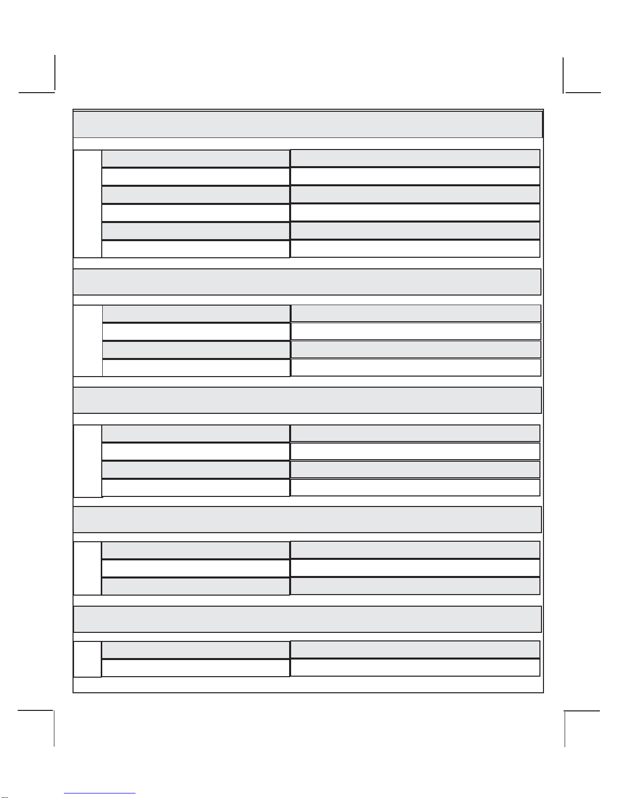
CONTROL MODULE: PART # 1365026
Selectamounting location inside the passenger compartment(upbehind the dashboard). The mounting
location selected must be within 24" of the ignition switch wiring harness to allow connection of the 6 pin
main wiring harness. Be certain that the chosen location will not interfere with proper operation of the
vehicle. Avoid mounting the module to or routing the wiring around the steering shaft/column, as the
moduleorwiring maywraparoundorblock thesteeringwheelpreventingproper control ofthevehicle. The
modulewillbe secured after allwiringis completed which willallowcomplete access until thejobis done.
Do Not Mount The Module In The Engine Compartment, as it is not waterproof.
SIREN: PART#AS9903
Select a location in the engine compartment that is not accessible from below the vehicle. The selected
location must be clear of hot or moving parts within the engine compartment The siren must be pointed
downwardtopreventwaterretentionand the open or flared end must be pointed awayfromandoutofthe
enginecompartment for maximum sound distribution. Beforesecuring the siren, check behindyour cho-
senlocation to assure that themounting screws will not penetrateany factory wiring orfluid lines. Secure
the siren mounting bracket using #8 self taping screws.
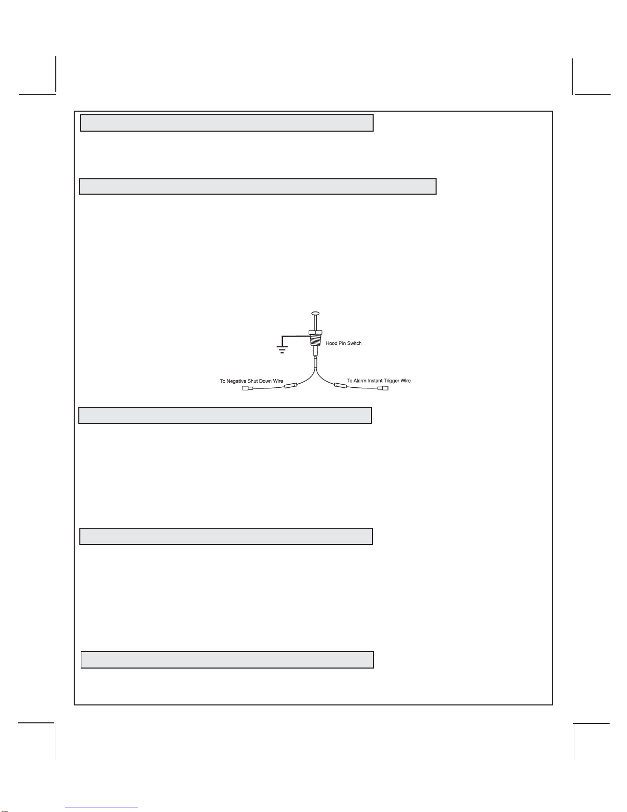
HOOD PIN SWITCH: PART#1363699
Thepinswitchincludedinthispackageis intended for protecting the hood area of the vehicle. In all cases,
theswitchmust be mounted toagrounded metal surface. When the pinswitch is activated, (hood open),
itwillsupplya ground to the inputwireactivatingthe alarm. In addition, the hood switchisrequired for the
safetyshut down of the remotestart unit. If the vehicleis being worked on, thishood switch prevents the
remote start activation even if the RF command to start is issued. This switch must be installed in all
applications. Failure to do so may result in personal injury or property damage.
THE PUSH-BUTTONPROGRAMSWITCH/LED/RECEIVER/ANTENNAASSEMBLY: PART# 1181201
The Superheterodyne ReceiverAntennaAssembly provided with this unit allows routing from below the
dashboardfor maximum operatingrange. Choosealocationabovethe belt line(dashboard)ofthevehicle
for best reception. Special considerations must be made for windshield glass as some newer vehicles
utilize a metallic shielded window glass that will inhibit or restrict RF reception. In these vehicles, route
theantenna toward a rearwindow location for best reception. Secure the antennawith double stick tape
provided.
SHOCK SENSOR: PART # AS9492a
Selectacentrallylocated, solidmounting surface for the shock sensor that willallowconsistentoperation
from all areas of the vehicle. The selected location must be within 18" of the control module to allow
routingandconnectingofthe4pinharness. Secure the shock sensor to the chosen location using two #8
selftappingsheetmetalscrews. Thesensorcanalsobesecuredtoanexistingdashbraceusingcabletie
straps. Whichevermounting method isused be sure to allow access to the sensitivity adjustment poten-
tiometer for use later in the installation.
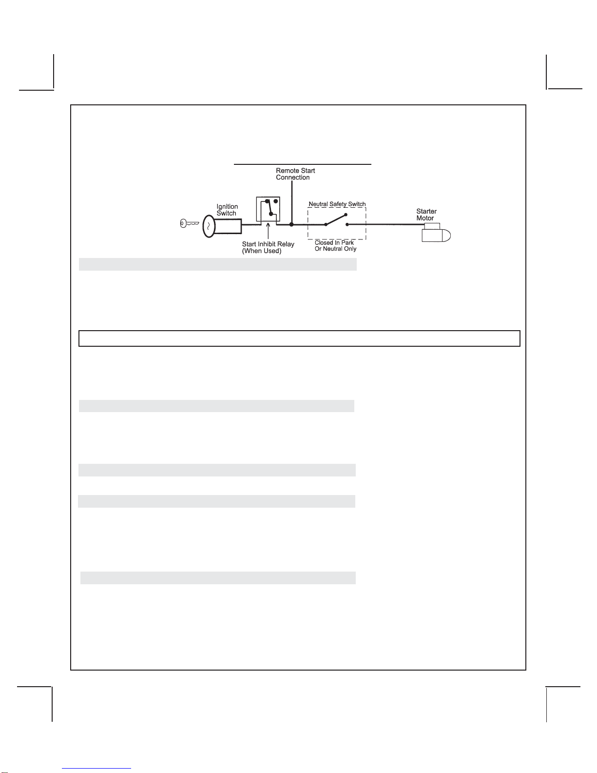
STARTER INHIBIT RELAY: PART # 1363731
Select a mounting location within 12" of the ignition switch's low current start solenoid wire. Secure the
relay to an existing harness in the chosen location using a cable tie around the relay's wiring harness.
CAUTION! Do not wire tie the metal bracket to an existing wiring harness as vibration may cause
chaffingandshortingdamagingthefactorywiring. Ifan existing harness is not available then
secure the relay's metal mounting tab to an under dash metal brace with a #8 self tapping
sheet metal screw. Wire the relay as per the diagram found later in this manual.
WARNING!! This unit is to be used in vehicles with AUTOMATIC TRANSMISSIONS only! Although this
combinationAlarm/Remote Start unit is a sophisticated system with many advanced features, IT MUST
NOT beinstalled into a vehicle withamanually operated transmission. Doing somayresult in serious
personalinjuryandpropertydamage.

128-8775b
6 of 32
6
IMPORTANT!
DONOTPLUGTHESIXPINMAINPOWER HARNESSORTHEMULTI PININPUT/OUTPUTHARNESS
INTO THE CONTROL MODULE UNTIL ALL CONNECTIONS TO THE VEHICLE HAVE BEEN MADE.
AFTER SELECTING YOUR TARGET WIRES AS DEFINED BELOW, DISCONNECT THE NEGATIVE
BATTERYCABLEFROMTHEVEHICLEBATTERYPRIORTOMAKINGANYCONNECTIONS.
Note: Do not remove the fuse holders from this wire harness. Fuses must be used and located
as close as possible to the power source for adequate protection of the vehicle.
WIRING THE 6 PIN MAIN POWER HARNESS: PART # 1123742
NOTE: Do not remove the fuse holders from this wire harness. Fuses must be
used and located as close as possible to the power source for adequate pro-
tection of the vehicle.
1 VIOLET Wire: Accessory Output
Connect this wire to theAccessory wire from the ignition switch. This wire will show + 12 volts when the
ignition switch is turned to the "ACCESSORY" or "ON" and "RUN" positions, and will show 0 volts when
the key is turned to the "OFF" and "START" or "CRANK" positions.
2 BLUE Wire: Ignition 1 Output
Connect this wire to the ignition 1 wire from the ignition switch. This wire will show +12 volts when the
ignition key is turned to the "ON" or "RUN" and the "START" or CRANK" positions, and will have 0 volts
when the key is turned to the "OFF" and "ACCESSORY" positions.
ForDieselApplications, this wire mustbeconnectedtotheignitioncircuit that powers the glow plugs if the
vehiclerequiresglowplugpre-heating.(See selectablefeatureBank3#11)
3 Fused RED WIRE: + 12 Volt Battery 2 Source
Locate the vehicle battery wire(s) at the ignition switch. Verification: These wires will register voltage in all
positions of the ignition switch. Connect the Red wire to the vehicle's battery wire. This wire provides power for
the start relay and the accessory relay.
4 Fused RED/WHITE WIRE: + 12 volt Battery 1 Source
Locate the vehicle battery wire(s) at the ignition switch. Verification: These wires will register voltage in all
positions of the ignition switch. Connect the Red w/White wire to the vehicle's battery wire. This wire provides
power for the control circuit as well as the ignition 1 and ignition 2 relays.
5 YELLOW Wire: Starter Output
Careful consideration for the connection of this wire must be made to prevent the vehicle from
starting while in gear. Understanding the difference between a mechanical and an electrical
Neutral Start Switch will allow you to properly identify the circuit and select the correct installa-
tion method. In addition you will realize why the connection of the safety wire is required for
all mechanical switch configurations.
Failureto make this connection properlycan result in personal injuryand property damage.
Inallinstallations it is the responsibilityofthe installing technician to testtheremote start unit and ensure
that the vehicle cannot start via RF control in any gear selection other than park or neutral.
Inbothmechanicalandelectricalneutralstartswitch configurations,theconnectionof theYellow wire will
bemadeto the low currentstartsolenoid wire of theignitionswitch harness. This wire willhave+12 volts
when the ignition switch is turned to the start (crank) position only. This wire will have 0 volts in all other
ignition switch positions.
NOTE: This wire must be connected to the vehicle side of the starter cut relay (when used). For the
electrical neutral switch configuration, this connection must be made between the starter inhibit relay,

128-8775b
7 of 32
7
( when used ) and the neutral safety switch as shown in the following diagram.
Failure to connect this wire to the ignition switch side of the of the neutral safety switch can result in
personalinjuryandpropertydamage.
SEENEUTRALSTARTSAFETYTESTFORFURTHERDETAILS.
YELLOWSTART WIRE DETAIL
6 GREEN Wire: Ignition 2 Output
Connect this wire to the ignition 2 wire from the ignition switch. This wire will show + 12 volts when the
ignition key is turned to the "ON" or "RUN" position and is some cases the "START" or CRANK" position.
This wire will show 0 volts when the key is turned to the "OFF" and "ACCESSORY" positions.
NOTE:See programming information (Bank 3Selection #2) concerning this wireto allow output during the
"START"mode.
WIRING THE 4 PINALTERNATE IGNITION HARNESS PART # 1123743
NOTE: Do not remove the fuse holders from this wire harness. Fuses must be
used and located as close as possible to the power source for adequate protec-
tion of the vehicle.
1 ORANGE/BLACK Wire: ParkingBrakeInput
This wire is used only when the turbo timer mode, Bank 3, feature # 16 is selected ON. This input insures
thatthevehicleparkingbrakeisappliedwheneverthevehicleissetupforandtheturbotimercircuitisused.
Thisinputmustswitchtogroundwhenthevehicle'sparkingbrakeisapplied.ConnecttheOrange/Blackwire
tothenegative output of the vehicle'sparkingbrakeswitch.
2 N/C
This cavity of the connector is empty.
3 RED/BLACK Wire: + 12 Volts Input
NOTE:TheRed/BlackandPinkaredrycontactsandmaybeusedfornegativeswitchingwhennecessary.
Connecting the Red/Black to chassis ground will result in Pink being ground when the R/S is activated.
Thisinputistobeconnectedtoaseparate,(OtherthanthewireRedorRed/Whiteisconnectedto),constant
on+12voltsourcewhich will supply + 12 volt power to theadditionalignitionoutput,(Pink),wire. Connect
this wire to a separate + 12 Volt source.
4 PINK Wire: Additional Ignition Output
Thiswirecanbe usedasanadditional+ 12VoltignitionoutputsuppliedbytheRed/Blackwire. Thisoutput
can be selected to be on or off during the start cycle. (See feature bank 3 selection # 8) Connect this wire
tothe third ignition circuit inthe vehicle and setthe selectable feature # 8of Bank 3 accordingto the way in
whichthevehicle's ignitionswitchoperates.

128-8775b
8 of 32
8
WIRING CONNECTIONS: 24 Pin Accessory Input/Output Harness PART #1123193
1 Dark Blue/Black Trace Wire: External Trigger Input
TheDark Blue/Black trace wire allows the remotestart unit to be activated from anexternal source. The
intentofthis wire is to allowtheunit to be controlled from a"POSSE/CAR-LINK"paging system or similar
device. When this wire receives a ground pulse, the unit will start the vehicle. Connect this wire to a
groundpulsedoutput from the controllingcircuit.
2 Brown w/ Black Trace Wire: Positive Inhibit Input Plus Trigger WhenArmed
TheBrownw/ BlackTrace wireprovides an instantshutdownforthe Remote StartControl modulewhen-
everitgets+12voltsalsotriggersthealarmwhen armed. If the brake lights switch in the vehicle switches
+ 12 volts to the brake light circuit, connect the Brown w/ Black trace wire to the output side of the brake
switch. Thiswill allow the RemoteStartto shutdown if an attemptis made to operatethe vehicle without
thekeywhilerunningunderthe control of the Remote Start. Inmost vehicles, in order to shiftinto gear,the
brake pedal must be depressed. The brake input will in turn cause the remote start unit to shut off.
3 Dark Green Wire: (-) Instant Trigger Input
TheDarkGreen wire is the instanton ground trigger input wire. Thiswiremust be connected to thehood
pin switch previously installed, and the trunk pin switch where used.
NOTE:Thiswire will beshuntedwhenremotecontrolchannel3 is accessed, (trunkrelease). Thiswirewill
remainshuntedall the while there isground present and for 5secondsafter the ground is removed. This
allows the operator to open the trunk via the remote transmitter without having to first disarm the alarm
system.
4 Green w/ Orange Trace Wire: Tachometer Input Signal
This wire will continually monitor the engine's tach rate while the unit is under power of the Remote Start
module. This wire will be routed to the vehicle ECM tach input or through the firewall into the engine
compartmentand connect to the negative side of the ignition coil. This Remote Startunit learns the tach
rate of the vehicle and in most cases will operate properly from one multi coil pack regardless of the
numberof cylinders. If the vehicle hasa single coil unitfor each cylinder,itmay be necessary to connect
this wire to more than one cylinder for proper tach reference. See Multi Coil PackAdaptor wiring detail
shownlaterin this manual for additionalinformation.
NOTE:ForHybridmodeselection,Bank3featureselection5,thisconnectionisnotrequired,theunitwill
start the vehicle and run the allotted time based on feature selection and crank duration.
5 Black Wire: Chassis Ground Source
ConnecttheBlackwiretoaknownvehicle ground source or to a solid clean metal part of thechassis. Be
certain to remove any paint or grease and secure this wire with a self tapping screw and ring terminal.
6 Green/Yellow Wire: Diesel Wait To Start Input
Thegreen/yellowwire, when connected tothewire that get +12 volts during the glowplug preheat stage
willdelay the starter outputuntil this wire drops the 12 volts. Inother words, in a Diesel vehicle withglow
plug preheat circuit, when the ignition is turned on, the vehicle will not crank until the glow plugs are hot
enoughtofiretheatomizedfueloilwheninjectedintothecylinder.Byconnectingthiswiretotheglowplug
+ 12 volt wire, when the remote start unit activates the ignition one output, the glow plug output also

128-8775b
9 of 32
9
activates. Theremotestart sees thegreen/yellowwithpositivevoltage and waitsforthistogoinactive( drop
the12volts) beforeactivatingthe startermotor. If thiswireis not used or you havedifficultyaccessing the
glow plug preheat circuit, you may elect to utilize the Diesel timed output as specified in Remote Start
featureselection #9. NOTE: Ifgreen/yellow is used, itwill override or negate any setting of feature #9.
7 Lt Blue/Green Wire : Delayed 300 mA PULSED OUTPUT / CHANNEL 5
The light blue/green wire pulses to ground via an independent RF channel from the keychain transmitter.
This is a transistorized, low current output, and should only be used to drive an external relay coil.
WARNING: Connecting the light blue/green to the high current switched output of trunk release circuits,
and some remote start trigger inputs, will damage the control module.
Connectthelightblue/green to terminal 86ofa30Aautomotiverelay,andwiretheremainingrelay contacts
toperform the selected functionof channel 5.
8 Blue/Red Wire : Delayed 300 mA PULSED OUTPUT / CHANNEL 7
Thelightblue/redwirepulsestogroundviaanindependentRFchannelfromthekeychaintransmitter.This
is a transistorized, low current output, and should only be used to drive an external relay coil.
WARNING: Connecting the light blue/red to the high current circuits,will damage the control module.
Connect the light blue/green to terminal 86 of a 30 A automotive relay, and wire the remaining relay
contacts to perform the selected function of channel 7.
9 Green w/ White trace Wire: Entry Illumination Ground Output
Thiswire provides a 30 secondground output, (300 mA Max.),whenever the remote isused to disarm
the alarm or to unlock the doors. It also provides a continuous pulsed output whenever the alarm is
triggered. This wire should be connected to an external relay and wired to the vehicles interior entry
lightingcircuitwhenever the optional Entry InteriorIllumination feature is desired. See belowforrelay
wiringdetails.
10 Black w/ White Trace Wire : 300 mA Horn Output
The black w/ white trace wire is provided to beep the vehicle’s horn. This is a transistorized low current
output, and should only be connected to the low current ground output from the vehicle’s horn switch.
Ifthevehicle uses a +12 VDC horn switch, thenconnect the black w/ whitetrace wire to terminal 86of the
AS 9256 relay ( or an equivalent 30 Amp automotive relay ), and connect relay terminal 85 to a fused
+12VDC battery source. Connectrelayterminal 87 to thevehicle’shorn switch output, andconnectrelay
terminal 30 to a fused + 12 VDC battery source.
11 White w/ Blue Trace Wire: 300mA(-) Ground Headlight Output
The White w/ Blue Trace wire is provided to operate the optional headlamp illumination feature of the
system. This is a low current (300mA) output and must be connected to an external relay to control the
high current switching circuit of the vehicle's headlamps. To use this option, connect the White /w Blue
Tracewire to terminal #86of a 30 ampautomotive relay. ConnectTerminals#85and# 30 to afused + 12
Volts source with a currentcapabilityequal to or in excessof the factory headlampfuse. Connect terminal
# 87 of the relay to the switched + 12 volt wire feeding the vehicle's headlamp circuit.
NOTE: Forground switched headlamp circuits, Connectthe White /w BlueTrace wire to terminal # 86 of
the relay. Connect Terminal #85 to a fused + 12 Volts source. Connect terminal # 30 to a clean chassis
ground. Connectterminal # 87 tothe ground switched headlampcontrol wire in thevehicle.

128-8775b
10 of 32
10
12 White Wire: Parking Light Flasher Output
This wire is the normally open contact of the on board parking light flash relay. Connect this wire to the
vehicle's parking light feed wire. This is the wire that gets switched on, either (+) or (-), when the vehicle's
parking light switch is activated.
13 Gray w/ Black Trace Wire: Negative Inhibit Input / Trigger WhenArmed
TheGrayw/BlackTracewireprovidesaninstantshutdownfortheRemote StartControl Module whenever
itisgrounded. This wire also trigger thealarmwhen armed when armed. Connect theGrayw/ Black trace
wiretothehood pin switch previously installed. This wire mustberoutedthrough a grommet in the firewall
andconnected to thehood pin switch. Ifconnecting to afactory hood pinswitch, it isrecommended that a
doublediode circuit be usedto prevent feed backof one device tothe other.
IMPORTANT! This connection is a safety wire and must be connected as shown and tested as specified.
Failure to do so may result in personal injury or property damage. See detail of wiring in the following
diagram. This wire may also be used if the vehicle brake light circuit switches ground to the brake lights. An
isolation diode must be used for ground switched brake light circuits and must be connected to the output
of the brake switch.
14 Purple Wire: (+)Door Trigger Input
If the vehicle's door courtesy light switches + 12 volts when the door is opened, (Some Fords and some
Imports), you must connect this wire to the positive output from one of the vehicle's door pin switches. In
most cases, the Purple wire will need to be connected to only one door switch no matter how many doors
the vehicle has as most door lighting circuits are wired in parallel. This wire will be shunted when remote
startingthe vehicle and will remain shunted, ifactive, while running under command of theremote start. If
this wire is active when the system is armed, the siren will emit three chirps. When the zone clears, the
siren will emit 1 chirp to confirm full arming.
NOTE:forvehicleswithinteriordelaylightingsee programming under title "Completing The Installation".
15 Brown Wire: (-)NegativeDoor Trigger
Ifthevehicle's door courtesy light switchesground when the door isopened,(Most GMs and Imports), you
mustconnectthiswiretothenegative output from one of the vehicle's door pin switches. Inmostcasesthe
Brownwirewillneedto be connected to only one doorswitchnomatter how many doors the vehicle hasas
most door lighting circuits are wired in parallel. This wire will be shunted when remote starting the vehicle
and will remain shunted, if active, while running under command of the remote start. If this wire is active
whenthesystem is armed, the sirenwillemit three chirps. When the zone clears,thesiren will emit 1 chirp
toconfirmfull arming.
Note: forvehicleswith interior delay lighting see programmingundertitle "Completing The Installation".
16 Lt Green Wire: (-) Instant Trigger Zone 1
Thisis a instant on groundtrigger input intended forthe connection of optional triggeringdevices. The

128-8775b
11 of 32
11
ground trigger output wire of motion detectors, microwave detectors, or glass break detectors, can be
connectedto this Light Green trigger input wire.
17 White w/ Black Trace Wire: (+) Siren Output
This is the positive siren feed wire. Route this wire through a grommet in the firewall to the siren location.
Connect the White w/ Black Trace wire to the Red wire of the Siren. Secure the Black wire of the Siren to
a known chassis ground or solid clean metal surface.
18 Dark Blue Wire: 300mA Pulsed Channel 3 Output (Trunk)
TheDarkBluewiresuppliesa 300mA ground pulsed output whenever channel three of thereceiveris
accessed. Pressingthe pre-programmed transmitter button for three seconds will access channel three.
This is a low current output and must be connected to a relay to supply power to the trunk release or the
circuit you wish to control. Connect the Dark Blue wire to terminal # 86 of a 30 amp automitive relay
Connect terminal # 85 of the relay to a fused + 12 volt source. Connect the common, normally open,
and normally closed contacts of the relay to perform the selected function of channel 3.
19 Green w/ Black Trace Wire: 300mA Pulsed Channel 4 Output
TheGreenw/BlackTracewiresuppliesa 300mAswitchedoutputwheneverchannelfourofthereceiveris
accessed. Pressingthepre-programmedtransmitterbutton(s)willprovidea1secondpulsetochannelfour
This is a low current output and must be connected to a relay to supply power to the device you intend to
control. ConnectGreenw/BlackTracewiretoterminal#86ofa30ampautomotiverelay. Connect terminal
#85 of the relay to a fused + 12 volt source. Connect the common, normally open, and normally closed
contacts of the relay to perform the selected function of the channel 4 output.
NOTE: This wire also can be used for defrost activation as dictated by the setting of feature # 1 of Bank 3.
Anytimethevehicleis running under control of the RemoteStartandChannel4isactivated,thendependent
on the selection of this feature, Green/Black will be activated for a 1 second pulse, or for 10 minutes.
Note this wire will, as a defrost output, only operate when running under control of the remote start,,,it will
notoperate when thevehicle is running under the control of the ignition key.
When the key & remote start are off, the output will operate as indicated above.
20 Lt Blue/Black Wire : (-) 300mA Selectable Output Channel 6
Thelight blue/green wirepulsestoground viaanindependentRFchannel fromthekeychaintransmitter.This
is a transistorized, low current output, and should only be used to drive an external relay coil.
WARNING: Connecting the light blue/black to the high current circuits, will damage the control module.
Connectthe light blue/blackto terminal 86of theAS - 9256 relay (or equivalent 30Aautomotive relay) and
wire the remaining relay contacts to perform the selected function of channel 6.

128-8775b
12 of 32
12
21 Light Blue Wire: Ground Output While Running (-) 300mA
Thiswire provides a 300mAgroundoutputthat becomes active 3seconds before the RemoteStartUnit
initializesand remains grounded whilerunning plus an additional4 seconds aftertheRemote StartUnit
turns off. In all of the applications described below, a relay will be required.
The Light Blue wire can be used to accommodate the following situations:
A. Sensor By Pass:
IfthereisaNon Plug in Sensor used with the alarmsystemanditisnot shunted during the Remote Start
activationperiod, then vibration ornoise from the running vehicle can causethe alarm to trigger. Inthis
case,connect the Light BlueWire to terminal #86of a external relay. Connect terminal# 85 of therelay
to a fused + 12 volt battery source. Cut the sensor's trigger wire and connect one end of the cut wire to
terminal #30 and the other end of the cut wire to terminal #87a. Just before the Remote Start unit is
activated,therelaycontactswillopen,preventingthesensor'soperation until the Remote Startunit shuts
off.
B. Additional Ignition Output:
Some vehicle's may require more than three ignition outputs to start and keep the vehicle's engine
running. If this is the case, connect the Light Blue wire to terminal #86 of an external relay. Connect
terminal#85toafused+12voltsource. Dependent on the vehicle's requirement, connect terminal #30,
to a fused + 12 volt source, or to ground, and connect terminal 87 to the vehicle to supply the additional
ignitionsource.
C. GM VATS Key Override:
If the vehicle has the General Motors VATS system installed, you will need to bypass the system while
the vehicle is operating under the control of the Remote Start Unit. To Do This:
1.Measure the resistance ofthe resistor pellet onthe ignition key thenselect a resistor within5% of the
key'svalue from the resistor pack supplied.
2.Locatethepairof VATSwiresinthe vehicle, usually a pairofthingaugewiresrunningfromtheignition
switch to the VATS control module.
NOTE: These wires are typically White w/ Black trace and Violet w/ Yellow trace, however in later model
Cadillacs, they are run through an orange sleeve, and are either both Black, both Yellow, or both White
wires. Consultthefactory service manual for additional information.
3.Connect the Light Blue WirefromtheRemote StartUnit to terminal#86 of an external relay. Connect
terminal #85 of the relay to a fused + 12 volt battery source.
4. Cut (#1) wire (as shown), and connect the ignition switch side of the cut wire to terminal #87a of the
relay. Connect the other side of the (#1) wire to terminal #30.
5.Connect the previously selected resistor from terminal #87 to the second (#2) wire(as shown).
NOTE:The above information andfollowingdiagram is for the GMVATS system only.

128-8775b
13 of 32
13
D. Anti-Grind Starter Circuit Connection:
This wire, when connected to a starter inhibit relay, as shown in the diagram below, will prevent the
customerfrom engaging the starterwhile the vehicle isrunning under control ofthe remote start.
Configured in this way, while the remote start is controlling the vehicle, the light blue wire has ground on
it all the time. This ground will cause the relay to energize preventing current flow through the normally
closed contacts. This will prevent a customer who inadvertently turns the ignition switch to the start
position, from sending current to the starter.
22 Orange w/ White Trace Wire : 300 mA (-) Output When Disarmed
N. O. Starter Disable Circuit, (Optional Relay Required).
Thiswireis provided to control anormallyopen startercut relay. Connect the orange/whitewireto terminal
86 of the relay. Connect relay terminal 85 to an ignition wire in the vehicle that is live when the key is in the
on and crank positions, and off when the key is in the off position. ( This is typically an ignition 1 source),
Cut the low current starter solenoid wire in the vehicle, and connect the car side of the cut wire to relay
terminal 87. Connect the key side of the cut wire to relay terminal 30.
NOTE: This is a normally opened starter cut arrangement, when power is removed from the secu-
rity system, the starter disable feature will remain operational, and the vehicle will not start.
Audiovox does not recommend using the Orange w/ White trace wire to interrupt anything but the
starting circuit of the vehicle.
23 Orange Wire: 300mA(-) Ground WhenArmed Output
This wire provides a 300 mA ground output when the alarm circuit is armed to control the starter inhibit
relay. Connectthe Orange wire to terminal#86(orange wire) of therelayprovided. Connect terminal #85
(red wire) of the relay to an ignition wire in the vehicle that is +12 volts when the ignition switch is turned
to the on and start positions and off when the key is off. Locate and cut the low current start solenoid
wire found at the vehicles ignition switch harness. This wire will have + 12 volts when the ignition key is
moved to the start (crank) position and will have 0 volts in all other key positions. Connect one side of
the cut wire to terminal #87a ( Black wire) of the relay. Connect the other side of the cut wire to terminal
#30 (White/Black wire) of the relay. See below for detail of wiring, also seeYellow Start wire detail for
connectiontovehicleconsiderations.

128-8775b
14 of 32
14
24 White w/ Red Trace Wire: Parking Light Flasher Input
Thiswireisthecommoncontactoftheonboardparkinglightflasherrelay. If the vehicle you are working on
has +12 volt switched parking lights, connect this wire to a fused + 12 volt source. (Max. 15Amps)
NOTE: Ifthe vehicle's parking lightsare ground switched, connectthis wire to chassisground.
Parking Light Wiring Detail
3 Pin Door Lock/Unlock Harness: (WhiteConnector)300mA Part#1122906
1 Red Wire: (-) Lock or (+) Unlock
TheRedwire provides a (-) Negative Pulsewhenlocking and a (+) Positive Pulsewhenunlocking.
2 Green: (+) Lock or (-) Unlock
TheGreenwireprovides a (+) Positive Pulse whenlockinganda (-) Negative Pulse when unlocking
3 Red/Black: (-) Second Unlock
The Red w/Black trace wire will provide a pulsed ground only, and will only provide an output when the
unlockbutton of the transmitter ispressed a second timeafter a first unlock commandwas issued. This is
used for second step unlock or all doors unlock in a two step circuit. In this arrangement, Red is used to
control the drivers door unlock relay, and the Red/Black will be used to control unlock of all other doors.
3 Wire Ground Switched Door Lock Circuits:
In this application, the Red wire of the door lock harness provides a ground pulse during the arming se-
quence,orpulsedgroundlock output. Connect the Red wire to thelowcurrentgroundsignal wire from the
factory door lock switch to the factory door lock relay.
TheGreenwireofthedoorlockharness provides a ground pulse during the disarming sequence, or pulsed
groundunlock output. Connect the Green wire to the low current ground signal wire from the factory door
unlock switch to the factory door unlock relay. See the following diagram for Wiring Detail.

128-8775b
15 of 32
15
3 WireGround Switched Door Lock/Unlock Wiring Detail
3 Wire Positive Switched Door Locks:
In this application, the Red wire of the door lock harness provides a + 12 volt pulse during the disarming
sequence,orpulsed12 volt unlock output. ConnecttheRedwiretothelowcurrent 12 volt signal wirefrom
the factory door unlock switch to the factory door unlock relay.
TheGreenwireofthe door lockharnessprovidesa + 12 volt pulse during the arming sequence, or pulsed
12 volt lock output. Connect the Green wire to the low current 12 volt signal wire from the factory door
lock switch to the factory door lock relay. See Below For Wiring Detail.
3 Wire Positive Switched Door Lock/Unlock Wiring Detail
Driver Priority Unlocking:
FordriverPriorityUnlockingthe Red/Black wire will be connectedtounlockalldoors,andthered,orgreen
willbe used to unlockthe drivers door dependentupon the door unlockpolarity. Please review the refer-
encediagram below and wire accordingto the vehicle typeyou are working on.
Negative Switch Driver Priority

128-8775b
16 of 32
16
Positive Switch Driver Priority
NOTE: Resistive Circuits, Multiplex Circuits As Well As 4 Wire Polarity Reversal and 5 Wire Alter-
nating 12 Volt Door Lock Control Circuits
Theseapplicationsrequiretheuseofadditionalcomponentswhichmayincluderelays,fixedresistors,orfor
convenience, a Door Lock Interface. Refer to the AUDIOVOX Door Lock Wiring Supplement and or the
Audiovoxfaxbackserviceforinformationonyour particular vehicle for properly connecting to these types of
circuits.
WIRING THE 4 PIN AUXILIARY OUTPUT HARNESS Part#1122585
The auxiliary 4 pin connector provides low current outputs to control various functions in the vehicle during
differentstagesoftheRemoteStartunit's operation. Understandingtheseoutputsand thetimeinwhichthey
occur will allow you to determine if they are needed for the particular vehicle you are working on as well as
how to use them.
1 Black w Blue Trace Wire: Pulsed Ground Output Before Start
The Black w/ Blue Trace wire will provide a 1 second 300 mA pulsed ground output 1.5 second before the
remotestartunitactivates as well aswhenthe transmitter is usedto disarm the system. Typical use forthis
output would be to disarm a factory theft deterrent system to prevent false triggering of the factory alarm
when the remote start unit engages or when the system is used to unlock the doors. This will also activate
when the transmitter is used to disarm/unlock the system
NOTE: Thisoutputcan be selected tooperatelike the door lock outputas set in alarm featuresetting #1 by
selecting feature #17 in Bank 3 for 2 Chirps.
2 Black w/ Light Green Trace Wire: Pulsed Ground Output After Start
TheBlackw/LightGreenTracewirewillprovidea1second300mApulsedgroundoutputafterthevehicleis
startedunder control of theremotestartunit. Typically this wire will be used tore-lockthevehicledoorsifthe
doorsunlockautomatically when the factory anti-theft systemisdisarmed. This wire will also activate when
the transmitter is used to arm/lock the system.
3 Black w/ Red Trace Wire: Pulsed Ground OutputAfter Shutdown
TheBlackw/RedTracewirewillprovidea1second300mApulsedgroundoutput after the remote start unit
shuts down. This output will occur regardless of whether the circuit times out or is manually terminated.
Typically this output will be used to re-lock the vehicle doors if the doors unlock automatically when the
ignition circuit transitions to off.

128-8775b
17 of 32
17
4 Black w/ Yellow Trace Wire: Ground Output During Start (Crank)
The Black w/ Yellow Trace wire will provide a 300 mAground output while the starter output of the remote
start unit is active. This output can be used to activate the Crank Low/Bulb Test wire found in some GM
vehicles. This wire is also referred to as the ECM wake up wire in some vehicles.
NOTE: Theoutputsabovearelowcurrentoutputsandmustbeused with a relay if the circuit's requirement
is more than 300 mA.
2 Pin Transponder Control Output: (Yellow Connector) Part#1122392
a: When selected for while remote start on, the Black wire will be active at the same time ign. 3 be-
comes active, and will remain active all the time the unit is operational under the control of the remote
start.
b: When selected for output during the start sequence, the Black wire will be active at the same time Ign.
3 becomes active, and will remain active until the vehicle has started. This will be used for one time read
transpondercircuits.
c: When the unit is selected for until ignition off, the Black wire will become active at the same time ign.
3 becomes active and will remain active even after the key take over and until the ignition in the vehicle is
turned off. This will allow the unit to be used for continuous read transponders circuits.
1 Black: 250mA Output (-)
The black wire switches on when the remote start is activated and will stay on as programmed in the
remotestartfeature Bank3 Feature 12.
2 Red: 250mA Output (+) 12 Volts Constant
Thisoutput is intended to allowthe control of atransponder bypass interface module ortransponder
bypass relay.
Additional Harnesses And Connectors For The System
4 Pin Upgrade Telematic Module: (ConnectorPort)
Red = + 5 Volts / Black = Ground / White = Data TX / Yellow = Data RX
Connect the 4 pin harness found in the Telematic one way or CArlink II kits to the mating port on the
controllingcircuit.
NOTE: Ifusing theTWOWAYTelematic module,only Ground,TX,and RX are usedon this port, the+ 12
volt supply for the two way module must be sourced separately or the unit will not operate.
6 Wire Antenna/Receiver Program Push-Button Switch/LED Connector: Part # 1123908
Plugthe previously routedantennaconnectorfrom theantennareceiverassembleinto thematingconnector
ofthecontrol module. This connectorsupplies12volts,groundand RF datainputandoutput,LEDcathode,
andValet Enableto and from theantenna receiver and the remotestartmodule. Becertainthis connector
is firmly seated making good contact to the control unit.
4 Pin Shock Sensor: (White Connector) Part # 1122591
TheRed(+12volt),Black(ground),Blue(pre-detect)andGreen(fulltriggerwhenarmed)wiresloadedinto

128-8775b
18 of 32
18
the white connector shell are the inputs/outputs of the shock sensor. Route the 4 wire harness from the
shock sensor to the remote start control unit and plug the 4 pin white connector into the mating 4 pin
connectorshell of the control module.
NOTE: While operating under the control of the remote start unit the shock sensor will be shunted, (by-
passed). Once the remote start shuts down, the shock sensor will be re-enabled.
4 PIN IN VEHICLE DATA BUS PORT (DBI Port) (ConnectorPort)
The 4 pin port located on the side of this module is for proprietary Audiovox data bus interface modules.
Thesemodulesareusedtoaccessavarietyoffeaturesinthevehiclewhichcanbeassimpleasdoortrigger
inputs,tomorecomplexdoorlocksoutputs, or transponder interfaces for remote starting. DO NOT connect
anythingtothisportother than theAudiovox IDBmodulesordamage to the Remote Startmodule will occur.
Allinstallationinstructionsfor the IDB modules willbepackagedwiththeindividualcomponentalongwith the
proper4pin wiring harnessrequirestoaccessthedatatransmit & receiveaswellastheproper voltage levels
fortheinterface.
TIMED START PROGRAM:
The Remote Start unit has the ability to start the vehicle automatically at timed intervals. This feature is
useful in extremely cold climates where starting the engine is the only means to keep the battery charged
and fluids warm. The operator has the option to have the unit start every 2 or 4 hours for a maximum of 48
hours. Factory preset is to start at 4 hour intervals. To select 2 or 4 hour automatic start timer:
1. Start By Holding the Push Button Switch found on the windshield mount receiver on.
2.While Holding the PushButton Switch TurnThe Ignition Switch OnThen Off
3a) Within 10 seconds of turning the ignition switch off, Release and then Push On and release the Push
Button Switch 2 times holding it on the second time until the siren and or lights flash and chirp 2 times
indicating that the 2 Hour Start Interval has successfully been set. or
3b) Within 10 seconds of turning the ignition switch off, (Step 2) Release and then Push On and release
the Push Button Switch 4 times holding it on the fourth time until the siren and or lights flash and chirp 4
times indicating that the 4 Hour Start Interval has successfully been set.
NOTE: Once selected, 2 or 4, this timer interval will remain in memory until it is manually changed. To
change,theabovesequencewillhavetobefollowed.
TIMED STARTOPERATION:
To begin thestarttimer, within 10 seconds of turning offtheignitionswitch,activatethe RF command to start
2 times. (Press the start button four times). The lights will flash and the siren will chirp 4 times. Indicating
timedintervalmode has beeninitiated.Thevehiclewill automatically startevery2or4 hours asprogrammed.
To cancel the timed start mode start the vehicle either by RF or by the ignition key.
TEMPERATURE START:
When Temperature Start, Bank 3 feature #13 is selected on, the temperature start mode can be activated
fromthe transmitter by pressing theLock + Option button simultaneously. Once activated, the unitwill start
1 time if the vehicle temperature reaches "0* " and then will run the allotted time.
DIESELENGINE SETTINGS:
NOTE: When selecting Diesel operation, (Bank 3 Feature #11), over gasoline, the only change is to the
ignition circuits. When Diesel is selected, the ignition circuits will power up 10, 15, or 20 seconds before
the start circuit. The intent of this feature is to allow the glow plug warming required by some diesel
engines. If your vehicle is a instant start diesel, it is not necessary to activate this feature.
ALSO: When selecting Diesel mode, be certain that the intended vehicle has a true tach reference and be
certain to connect the tach input wire. Also note, if the "Diesel Wait to Start" input is connected,
(Green/Yellow) this wirewill takeprecedence over the Dieselselection of bank 3 feature11.

128-8775b
19 of 32
19
Monitoring The Vehicle's Engine: (ProgramFeature#5Bank3)
There are 4 ways that the remote start monitors the engine running, one or the other must be selected for
your application for the remote start to operate correctly.
1)VOLTAGESENSESETTING:
The unit will monitor the voltage level of the battery during remote start, wait for the voltage to drop while
cranking,thenlookforthevoltagelevelto go above the level it was before the vehicle began tocrankwhich
indicates the vehicle is running. Feature #14 of Bank 3 must be set for preset time or the voltage sense
feature will not operate indicated by the parking lights flashing 7 times.
2)TACH RATESETTING:
1. Turn the ignition key to the On position.
2. Press and release the valet/program push button switch 3 times.
3. Immediately turn the ignition key Off.
4. Press and hold the valet/program push button switch, then start the vehicle using the key.
5. When the unit senses the tach signal, the parking lights will begin to flash.
6.Releasethevalet/programpushbutton switch. The parking lights will turn onforthreesecondstoindicate
that the learned tach signal is stored and the unit is out of the tach learn mode.
NOTE:Ifthe unit fails tolearntachrateduetoanimproper tachometer connection or apoortachsource,the
parking lights will not flash. To correct this situation, locate and connect the Green/Orange wire to the
propertach signal, and thenrepeat the tach learnroutine.
3)DBI TACH SETTING
Selectingthis setting in the optionmenu indicates that youhavea DBI module andhave determined that a
tach signal is available for the vehicle you are connecting to. The unit will look at the DBI data port for the
tach signal. If the vehicle fails to start, or the unit flashes 7 times, recheck the DBI manual to insure that
tachis available foryour vehicle. If not the tach connection wire, Green/Orange must be used.
4)HYBRIDSETTING:
Selectingthissetting in the option menuallowsfor Hybrid vehicles. Also feature #14of Bank 3 must beset
for preset time or the Hybrid feature will not operate indicated by the parking lights flashing 7 times.
CRANKAVERAGING:
WhenFeature14Bank3issetforcrankaveraging,theremotestartunitconstantlymonitorsandlearnsthe
cranking patterns of the vehicle each time the car is started with the key. The vehicle must be started
atleast 4 times with the key for the crank averaging circuit to begin it's monitoring the vehicle's engine.
DIAGNOSTICS:
Enter Bank 3 and turn on selectable feature # 9 as described on the front pages of this manual.
NOTE: Diagnosticmodeisatemporary mode. Once you have accessed the diagnostic mode,theunitwill
pausefortwosecondsthenbegintoflashthe last stored shut down code. This code will be displayed three
times in succession, then the unit will automatically exit the diagnostic on mode.
Theparkinglights will flash a numberoftimes indicating the reason for thelastremote start shutdown. The
light flash indications are as follows:
1 Flash Run timer expired
2 Flashes Low or no tach signal (RPM)
3 Flashes Positive inhibit wire activation
4 Flashes NA
5 Flashes RF shutdown, Remote signal received, or manual start trigger wire reactivated.
6 Flashes High tach signal (RPM)
7 Flashes Tach signal has not been learned
8 Flashes Negative inhibit wire

128-8775b
20 of 32
20
Multi Coil PackAdaptor: (Optional)
The multi coil pack adapter, is designed for use with vehicles that do not respond to single coil tach
programming. Althoughthetachresolutionof this circuit is designedto interface direct with mostvehicles,
there may be an occasion where the following circuit may be required. Construct the adaptor as shown
below.
To use the adaptor, the Green/Black wires must connect to the negative side of the ignition coil(s).
1. For vehicles utilizing independent coils per cylinder, connect the three Green/Black leads to alternate
coils. To achieve optimum performance the coil signals must be evenly distributed. This is accom-
plishedby first mapping outthe firing order of the engine ingroupsofas indicated below. Drawa circle
around any of the columns. The Green/Black wires should be connected to the negative (-) terminal of
the respective cylinder number which appears in any of the circles.
2. For vehicles utilizing 2 cylinder firing per coil pack, connect Green/Black to the tach side of each coil
pack. For 8 cylinder, four coil systems, connect to any of the three coils.
3. Connect theYellow wire to a +12 volt ignition 1 source. This wire will have +12 volts with the ignition in
the on and start position and have 0 volts with the ignition in the off position.
4. Connectthe Green wireto the (Green)or (Orange/Green) tachinput of theAudiovox remote startunit.
TESTINGYOURINSTALLATION:
WARNING!! The following procedure mustbeperformedafterthe installationofanyRemoteStartDevice.
It is the responsibility of the installing technician to complete these tests. Failure to test the unit in the
followingmannermay result in personalinjury, propertydamage, or both.
HOOD PIN SAFETY SHUT DOWN:
Theintentof the hood pin safety shutdownis to prevent the RemoteStartunit from being activated whilea
mechanicorvehicleownerisperformingnormalroutinevehiclemaintenance.
To test the integrity of this circuit:
1. With the drivers window in the down position, start the vehicle using the RF transmitter.
2. Reach inside the car and pull the hood release.
3. Raise the hood and confirm that the remote start unit shuts down.
Iftheunitfails this test, recheck your pin switchconnectiontothe Gray/Black wire of the RemoteStartUnit.
DONOTRELEASETHIS VEHICLE TO THE CONSUMER UNTIL YOU CONFIRMTHE
OPERATION OF THE HOOD PIN SAFETYSHUT DOWN FEATURE.
Other manuals for APS-997C
1
Table of contents