iDataLink ADS-AL(DL)-HA1-EN User manual

NOTICE: The manufacturer will accept no responsibility for any electrical damage resulting from
improper installation of this product, be that either damage to the vehicle itself or to the installed
device. This device must be installed by a certified technician. This guide has been written for
properly trained technicians; a certain level of skill & knowledge is therefore assumed. Please
reviewtheInstallation Guide carefullybefore beginning any work.
!
The brand names and logos found in this guide are property of their respective owners. Automotive Data Solutions Inc. © 2016
U.S. PATENT NO. 8,856,780
Automotive Data Solutions Inc.
INSTALL GUIDE
ADS-AL(DL)-HA1-EN
AVAILABLE FOR: ADS-AL CA
HA1
Rev. Date: August 08, 2016
Doc. No.: ##29247##
20160808
Alarms & Remote Start

U.S. Patent No. 8,856,780
MAKE
MODEL
YEAR
INSTALL TYPE
FEATURES
DATA IMMOBILIZER BYPASS
ARM OEM ALARM
DISARM OEM ALARM
DOOR LOCK
DOOR UNLOCK
TRUNK/HATCH RELEASE
POWER LIFTGATE
POWER SLIDING DOOR (L)
POWER SLIDING DOOR (R)
DOOR STATUS OUTPUT
TRUNK STATUS OUTPUT
HOOD STATUS OUTPUT**
TACHOMETER OUTPUT
E-BRAKE OUTPUT
A/M ALARM CTRL FROM OEM REMOTES
A/M RS CTRL FROM OEM REMOTES
AUTOLIGHT CTRL*
ACURA
EL 1.7 01-05 2 • • • • • •
RSX 02-06 2 • • • • • •
TL 04-083•••••• ••••••••
TSX 04-081•••••• ••••••••
HONDA
Accord / Hybrid 03-07 1 • • • • • • • • • • • • • •
Civic / Hybrid 01-05 2 • • • • • •
CR-V 02-06 2 • • • • •
Element 03-11 2 • • • • •
Odyssey 05-10 1 • • • • • • • • • • • • • • • •
Ridgeline 06-14 1 • • • • • • • • • • • •
*This feature will unlock then lock the vehicle’s doors on RS shutdown. To turn it off, deactivate the RAP shutdown.
**Available only if vehicle is equipped with factory hood switch.
INSTALL TYPE SELECTION
Page 2 of 11 ADS-AL(DL)-HA1-EN 20160808
INSTALL GUIDE
Automotive Data Solutions Inc. © 2016
ALL IN ONE
Honda/acura
Doc. No.: ##29247##

U.S. Patent No. 8,856,780
WARNING: READ CAREFULLY
IMPORTANT
I Ground When Running from Remote Starter must be provided BEFORE Ignition.
Failure to comply may result in immobilizer bypass malfunction during remote start.
II If Ground When Running from Remote Starter CAN’T be provided BEFORE Ignition, use a separate TB-HA for immobilizer bypass ONLY.
III - DO NOT program unlock before start on the Remote Starter.
- DO NOT change Remote Starter OEM alarm control default settings.
Failure to comply may result in product malfunction.
Page 3 of 11 ADS-AL(DL)-HA1-EN 20160808
INSTALL GUIDE
Automotive Data Solutions Inc. © 2016
ALL IN ONE
Honda/acura
Doc. No.: ##29247##

U.S. Patent No. 8,856,780
TYPE 1 - WIRE CROSS REFERENCE CHART
MAKE
MODEL
YEAR
WIRE
DESCRIPTION
CONNECTOR
NAME
CONNECTOR
COLOR
CONNECTOR
TYPE
POSITION
WIRE
COLOR
POLARITY
MODULE
LOCATION
COMPONENT
LOCATOR
ACURA
TSX 04-05
Ignition 1 ~ White 7 pin 6 Black/Yellow (+) Ignition switch ~
Ignition 2 ~ Green 21 pin 9 Yellow (+) Dash fuse box, driver side ~
Data ~ White 7 pin 2 Red/Blue (DATA) Ignition switch ~
Security Light ~ White 7 pin 5 Blue/Orange (-) Ignition switch ~
Doorlock Data ~ Green 21 pin 4 Brown/Red (DATA) Dash fuse box, driver side ~
TSX 06-08
Ignition ~ White 7 pin 6 Black/Yellow (+) Ignition switch ~
Ignition 2 ~ Green 21 pin 9 Yellow (+) Dash fuse box, driver side ~
Data ~ White 7 pin 2 Red (DATA) Ignition switch ~
Security Light ~ White 7 pin 5 Orange (-) Ignition switch ~
Doorlock Data ~ Green 21 pin 4 Brown/Red (DATA) Dash fuse box, driver side ~
HONDA
Accord 03-07
Ignition ~ White 7 pin 6 Black/Yellow (+) Ignition switch ~
Ignition 2 ~ Green 21 pin 9 Yellow (+) Dash fuse box, driver side ~
Data ~ White 7 pin 2 Red/Blue (DATA) Ignition switch ~
Security Light ~ White 7 pin 5 Blue/Orange (-) Ignition switch ~
Doorlock Data ~ Green 21 pin 4 Brown/Red (DATA) In driver door harness ~
Accord Hybrid 05
Ignition ~ White 7 pin 6 Black/Yellow (+) Ignition switch ~
Ignition 2 ~ Green 21 pin 9 Yellow (+) Dash fuse box, driver side ~
Data ~ White 7 pin 2 Yellow (DATA) Ignition switch ~
Security Light ~ White 7 pin 5 Red (-) Ignition switch ~
Doorlock Data ~ ~ 21 pin 4 LtGreen (DATA) Dash fuse box, driver side ~
Accord Hybrid 06-07
Ignition ~ White 7 pin 6 Black/Yellow (+) Ignition switch ~
Ignition 2 ~ Green 21 pin 9 Yellow (+) Dash fuse box, driver side ~
Data ~ White 7 pin 2 Yellow (DATA) Ignition switch ~
Security Light ~ White 7 pin 5 Red (-) Ignition switch ~
Doorlock Data ~ Green 21 pin 4 Brown/Red (DATA) Dash fuse box, driver side ~
Odyssey 05-10
Ignition ~ Green 7 pin 6 Black/Yellow (+) Ignition switch ~
Ignition 2 ~ Green 21 pin 9 Yellow (+) Dash fuse box, driver side ~
Data ~ Green 7 pin 2 Red/Blue (DATA) Ignition switch ~
Security Light ~ Green 7 pin 5 Blue/Orange (-) Ignition switch ~
Doorlock Data ~ Green 21 pin 4 Green/Red (DATA) In driver door harness ~
Ridgeline 06-14
Ignition ~ Green 7 pin 6 Black/Green (+) Ignition switch ~
Ignition 2 ~ Green 21 pin 9 Yellow (+) Dash fuse box, driver side ~
Data ~ Green 7 pin 2 Red/Blue (DATA) Ignition switch ~
Security Light ~ Green 7 pin 5 Blue/Orange (-) Ignition switch ~
Doorlock Data ~ Green 21 pin 4 Brown/Black (DATA) Dash fuse box, driver side ~
Page 4 of 11 ADS-AL(DL)-HA1-EN 20160808
INSTALL GUIDE
Automotive Data Solutions Inc. © 2016
ALL IN ONE
Honda/acura
Doc. No.: ##29247##

U.S. Patent No. 8,856,780
TYPE 1 - WIRING DIAGRAM
Page 5 of 11 ADS-AL(DL)-HA1-EN 20160808
INSTALL GUIDE
Automotive Data Solutions Inc. © 2016
ALL IN ONE
Honda/acura
1415161718 10111213192021
23 1456789
11 22 33 44 55 66 77
4
56
2
9
87A
87
85 86
30
DATA
SECURITY LIGHT
<- REQUIRED
<- REQUIRED
<- REQUIRED
<- REQUIRED
<- REQUIRED
<- REQUIRED
<- REQUIRED
<- REQUIRED
<- REQUIRED
<- REQUIRED
<- REQUIRED
<- REQUIRED
GWR (-) INPUT - BLUE/WHITE
LOCK/ARM (-) INPUT - GREEN/BLACK
GROUND (-)
GROUND (-)
GWR (-) OUTPUT
GWR (-) OUTPUT
LOCK (-) OUTPUTLOCK (-) OUTPUT
UNLOCK (-) OUTPUT
UNLOCK (-) OUTPUT
12V (+)
12V (+)
12V (+) - RED
12V (+) - RED
GROUND - BLACK
GROUND - BLACK
(NC) WHITE
(NC) WHITE
UNLOCK (-) INPUT - BLUE/BLACKUNLOCK (-) INPUT - BLUE/BLACK
TRUNK (-) INPUT - RED/WHITE
TRUNK (-) OUTPUT
TRUNK (-) OUTPUT
DISARM (-) INPUT - BROWN
DISARM (-) OUTPUT
DISARM (-) OUTPUT
LEFT SLIDING DOOR (-) INPUT - PURPLE/YELLOW
LEFT SLIDING DOOR (-) OUTPUT
RIGHT SLIDING DOOR (-) INPUT - PURPLE/BLACK
RIGHT SLIDING DOOR (-) OUTPUT
(NC) WHITE
(NC) WHITE
STARTER (+) INPUT - BLACK/WHITE
STARTER (+) OUTPUT
STARTER (+) OUTPUT
E-BRAKE STATUS (-) OUTPUT - GREEN
E-BRAKE (-) INPUTE-BRAKE (-) INPUT
TACH (AC) OUTPUT - PURPLE/WHITE
TACH (AC) INPUTTACH (AC) INPUT
YELLOW/BLACK - DOOR STATUS (-) OUTPUT
BROWN/RED (NC)
BROWN/RED (NC)
BLUE/RED (NC)
BLUE/RED (NC)
YELLOW/RED - TRUNK STATUS (-) OUTPUT
YELLOW - HOOD STATUS (-) OUTPUT*
BROWN/YELLOW (NC)
BROWN/YELLOW (NC)
ORANGE/BLACK - KEY DATA
ORANGE/WHITE (NC)
ORANGE/WHITE (NC)
ORANGE - DOORLOCK DATA
DOORLOCK DATA
PINK/BLACK (NC)PINK/BLACK (NC)
BLUE/YELLOW (NC)
BLUE/YELLOW (NC)
GREEN/RED (NC)
GREEN/RED (NC)
GREEN/YELLOW (NC)
GREEN/YELLOW (NC)
GRAY/RED (NC)
GRAY/RED (NC)
PINK - IGNITION (+) INPUT
21 PIN CONNECTOR
LOCATED AT DRIVER’S SIDE FUSEBOX
WHITE/BLACK - SECURITY LIGHT INPUT
WHITE/RED - SECURITY LIGHT OUTPUT
WHITE (NC)
WHITE (NC)
GRAY/YELLOW (NC)
GRAY/YELLOW (NC)
REQUIRED ->
OPTIONAL ->
OPTIONAL ->
HOOD STATUS (-) INPUTHOOD STATUS (-) INPUT
TRUNK STATUS (-) INPUT
DOOR STATUS (-) INPUT
REFER TO WIRING CROSS REFERENCE
CHART FOR WIRE COLOR
NOT REQUIRED IN DATA MODE (1-WAY)
NOT REQUIRED IN DATA MODE (2-WAY)
LEGEND
USE DATA MODE
OR HARDWIRE MODE
DATA MODE
DATA MODE
REMOTE STARTER
WARNING
AS MODULE PROGRAMMING PROCEDURE WILL ONLY
FUNCTION WITH THE VEHICLE’S MASTER KEY,
IT IS IMPORTANT TO OBTAIN ALL VALID KEYS IN ORDER
TO IDENTIFY THE MASTER KEY.
NOTE
SINCE THE MODULE INCLUDES A ‘DISARM INPUT’ FEATURE,
BOTH ‘UNLOCK BEFORE START’ AND ‘LOCK AFTER START’
FEATURES ARE NOT REQUIRED.
IGNITION 1 (+)
IGNITION 2 (+)
12V (+)
CONNECTION IS ONLY REQUIRED IF REMOTE START CONTROL
FROM OEM REMOTES IS DESIRED.
Doc. No.: ##29247##

U.S. Patent No. 8,856,780
TYPE 2 - WIRE CROSS REFERENCE CHART
MAKE
MODEL
YEAR
WIRE
DESCRIPTION
CONNECTOR
NAME
CONNECTOR
COLOR
CONNECTOR
TYPE
POSITION
WIRE
COLOR
POLARITY
MODULE
LOCATION
COMPONENT
LOCATOR
ACURA
RSX 01-03
Ignition ~ Green 7 pin 6 Yellow/Black (+) Ignition switch ~
Data ~ Green 7 pin 2 Red/Blue (DATA) Ignition switch ~
Security Light ~ Green 7 pin 5 Blue/Orange (-) Ignition switch ~
Doorlock Data K ~ 17 pin 2 Blue/Orange (DATA) Top of driver side fuse box ~
RSX 04-06
Ignition ~ Green 7 pin 6 Black/Yellow (+) Ignition switch ~
Data ~ Green 7 pin 2 Red/Blue (DATA) Ignition switch ~
Security Light ~ Green 7 pin 5 Blue/Orange (-) Ignition switch ~
Doorlock Data K ~ 17 pin 2 Blue/Orange (DATA) Top of driver side fuse box ~
EL 1.7 01-05
Ignition ~ Green 7 pin 6 Yellow/Black (+) Ignition switch ~
Data ~ Green 7 pin 2 Red/Blue (DATA) Ignition switch ~
Security Light ~ Green 7 pin 5 Blue/Orange (-) Ignition switch ~
Doorlock Data K ~ 17 pin 2 Blue/Orange (DATA) Top of driver side fuse box ~
HONDA
Civic/
Civic Hybrid 01-05
Ignition ~ Green 7 pin 6 Yellow/Black (+) Ignition switch ~
Data ~ Green 7 pin 2 Red/Blue (DATA) Ignition switch ~
Security Light ~ Green 7 pin 5 Blue/Orange (-) Ignition switch ~
Doorlock Data K ~ 17 pin 2 Blue/Orange (DATA) Top of driver side fuse box ~
CR-V 02-04
Ignition ~ Green 7 pin 6 Yellow/Black (+) Ignition switch ~
Data ~ Green 7 pin 2 White (DATA) Ignition switch ~
Security Light ~ Green 7 pin 5 Blue/Orange (-) Ignition switch ~
Doorlock Data K ~ 17 pin 2 Blue/Orange (DATA) Top of driver side fuse box ~
CR-V 05-06
Ignition ~ Green 7 pin 6 Black/Yellow (+) Ignition switch ~
Data ~ Green 7 pin 2 White (DATA) Ignition switch ~
Security Light ~ Green 7 pin 5 Blue/Orange (-) Ignition switch ~
Doorlock Data K ~ 17 pin 2 Blue/Orange (DATA) Top of driver side fuse box ~
Element 03-11
Ignition ~ Green 7 pin 6 Black/Yellow (+) Ignition switch ~
Data ~ Green 7 pin 2 White (DATA) Ignition switch ~
Security Light ~ Green 7 pin 5 Blue/Orange (-) Ignition switch ~
Doorlock Data K ~ 17 pin 2 Blue/Orange (DATA) Top of driver side fuse box ~
Page 6 of 11 ADS-AL(DL)-HA1-EN 20160808
INSTALL GUIDE
Automotive Data Solutions Inc. © 2016
ALL IN ONE
Honda/acura
Doc. No.: ##29247##

U.S. Patent No. 8,856,780
TYPE 2 - WIRING DIAGRAM
Page 7 of 11 ADS-AL(DL)-HA1-EN 20160808
INSTALL GUIDE
Automotive Data Solutions Inc. © 2016
ALL IN ONE
Honda/acura
5
141312
4 76321
171615111098
11 22 33 44 55 66 77
2
56
2
DATA
SECURITY LIGHT
IGNITION (+)
<- REQUIRED
<- REQUIRED
<- REQUIRED
<- REQUIRED
<- REQUIRED
<- REQUIRED
GWR (-) INPUT - BLUE/WHITE
LOCK/ARM (-) INPUT - GREEN/BLACK
GROUND (-)
GROUND (-)
GWR (-) OUTPUT
GWR (-) OUTPUT
LOCK (-) OUTPUTLOCK (-) OUTPUT
UNLOCK (-) OUTPUT
UNLOCK (-) OUTPUT
12V (+)
12V (+)
12V (+) - RED
12V (+) - RED
GROUND - BLACK
GROUND - BLACK
(NC) NO WIRE
(NC) NO WIRE
UNLOCK/DISARM (-) INPUT - BLUE/BLACKUNLOCK/DISARM (-) INPUT - BLUE/BLACK
TRUNK (-) INPUT - RED/WHITE
TRUNK (-) OUTPUT
TRUNK (-) OUTPUT
(NC) BROWN
(NC) BROWN
(NC) WHITE
(NC) WHITE
(NC) BLACK/WHITE
(NC) BLACK/WHITE
(NC) GREEN
(NC) GREEN
(NC) PURPLE/WHITE
(NC) PURPLE/WHITE
YELLOW/BLACK (NC)
YELLOW/BLACK (NC)
BROWN/RED (NC)
BROWN/RED (NC)
BLUE/RED (NC)
BLUE/RED (NC)
YELLOW/RED (NC)
YELLOW/RED (NC)
YELLOW (NC)
YELLOW (NC)
BROWN/YELLOW (NC)
BROWN/YELLOW (NC)
ORANGE/BLACK - KEY DATA
ORANGE/WHITE - DOORLOCK DATA
ORANGE (NC)
ORANGE (NC)
PINK/BLACK (NC)
PINK/BLACK (NC)
BLUE/YELLOW (NC)
BLUE/YELLOW (NC)
GREEN/RED (NC)
GREEN/RED (NC)
GREEN/YELLOW (NC)
GREEN/YELLOW (NC)
GRAY/RED (NC)
GRAY/RED (NC)
PINK - IGNITION (+) INPUT
17 PIN CONNECTOR
LOCATED BEHIND DRIVER’S SIDE FUSEBOX
WHITE/BLACK - SECURITY LIGHT INPUT
WHITE/RED - SECURITY LIGHT OUTPUT
WHITE (NC)
WHITE (NC)
GRAY/YELLOW (NC)
GRAY/YELLOW (NC)
NOT REQUIRED IN DATA MODE (1-WAY)
NOT REQUIRED IN DATA MODE (2-WAY)
LEGEND
USE DATA MODE
OR HARDWIRE MODE
DATA MODE
DATA MODE
WARNING
AS MODULE PROGRAMMING PROCEDURE WILL ONLY
FUNCTION WITH THE VEHICLE’S MASTER KEY,
IT IS IMPORTANT TO OBTAIN ALL VALID KEYS IN ORDER
TO IDENTIFY THE MASTER KEY.
REMOTE STARTER
DOORLOCK DATA
(NC) PURPLE/YELLOW
GROUND (-) INPUT -
GROUND (-) INPUT - PURPLE/BLACK
CONNECT TO GROUND
TO ENABLE AUTOMATIC
RELOCK AFTER START
Doc. No.: ##29247##

U.S. Patent No. 8,856,780
TYPE 3 - WIRE CROSS REFERENCE CHART
MAKE
MODEL
YEAR
WIRE
DESCRIPTION
CONNECTOR
NAME
CONNECTOR
COLOR
CONNECTOR
TYPE
POSITION
WIRE
COLOR
POLARITY
MODULE
LOCATION
COMPONENT
LOCATOR
ACURA
TL 04-06
Ignition 1 ~ White 7 pin 6 Black/Green (+) Ignition switch ~
Ignition 2 ~ Green 5 pin 3 Yellow (+) Keyless module, above brake pedal ~
Data ~ White 7 pin 2 Red/Blue (DATA) Ignition switch ~
Security Light ~ White 7 pin 5 Blue/Orange (-) Ignition switch ~
Doorlock Data ~ Green 21 pin 4 Brown/Black (DATA) Dash fuse box, driver side ~
TL 07-08
Ignition 1 ~ White 7 pin 6 Black/Green (+) Ignition switch ~
Ignition 2 ~ Green 5 pin 3 Yellow (+) Keyless module, above brake pedal ~
Data ~ White 7 pin 2 Yellow (DATA) Ignition switch ~
Security Light ~ White 7 pin 5 Orange (-) Ignition switch ~
Doorlock Data ~ Green 21 pin 4 Brown/Black (DATA) Dash fuse box, driver side ~
Page 8 of 11 ADS-AL(DL)-HA1-EN 20160808
INSTALL GUIDE
Automotive Data Solutions Inc. © 2016
ALL IN ONE
Honda/acura
Doc. No.: ##29247##

U.S. Patent No. 8,856,780
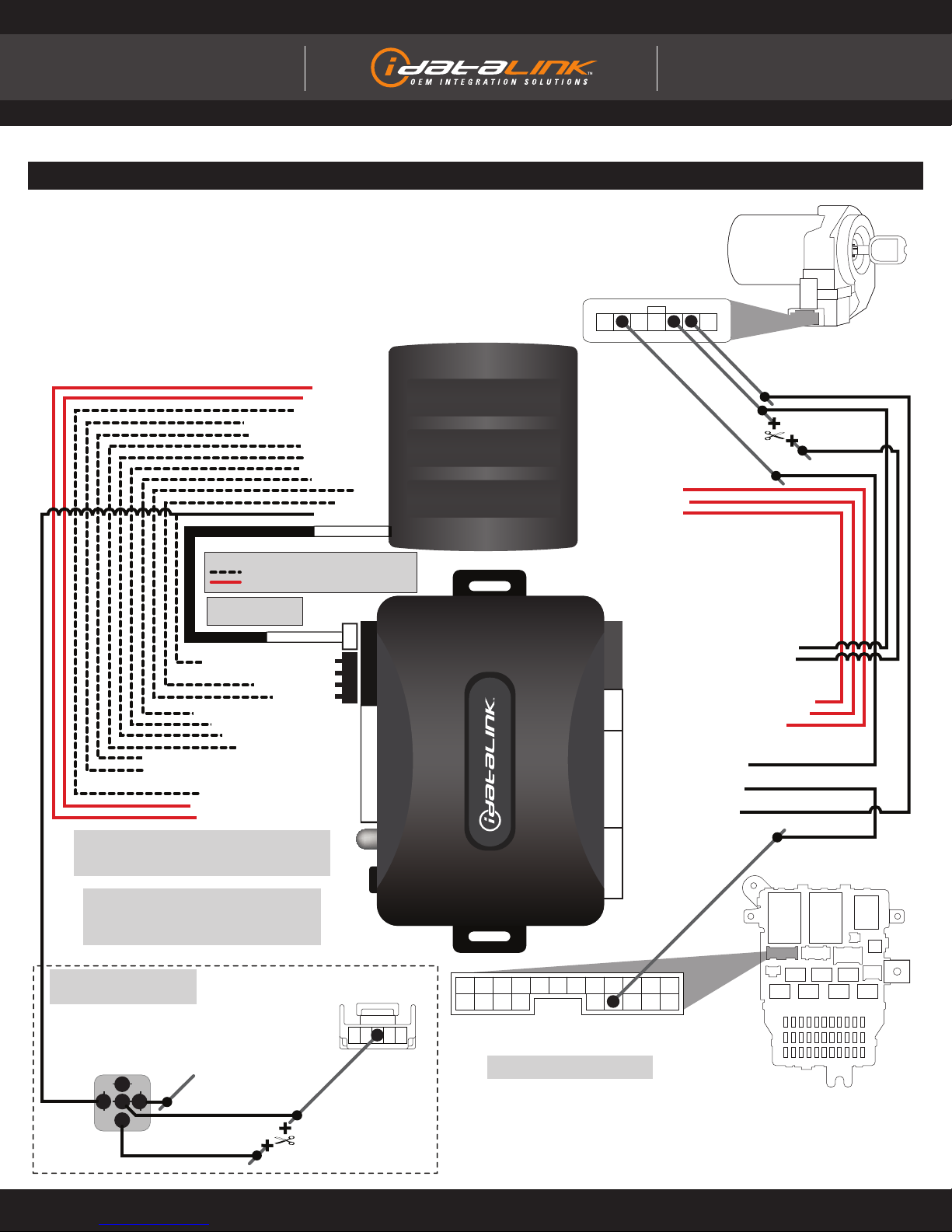
TYPE 3 - WIRING DIAGRAM
Page 9 of 11 ADS-AL(DL)-HA1-EN 20160808
INSTALL GUIDE
Automotive Data Solutions Inc. © 2016
ALL IN ONE
Honda/acura
1122334455
1415161718 10111213192021
23 1456789
11 22 33 44 55 66 77
4
56
2
3
87A
87
85 86
30
KEYLESS MODULE - ABOVE BRAKE PEDAL
GREEN CONNECTOR
DATA
SECURITY LIGHT
<- REQUIRED
<- REQUIRED
<- REQUIRED
<- REQUIRED
<- REQUIRED
<- REQUIRED
<- REQUIRED
<- REQUIRED
<- REQUIRED
<- REQUIRED
<- REQUIRED
<- REQUIRED
GWR (-) INPUT - BLUE/WHITE
LOCK/ARM (-) INPUT - GREEN/BLACK
GROUND (-)
GROUND (-)
GWR (-) OUTPUT
GWR (-) OUTPUT
LOCK (-) OUTPUTLOCK (-) OUTPUT
UNLOCK (-) OUTPUT
UNLOCK (-) OUTPUT
12V (+)
12V (+)
12V (+) - RED
12V (+) - RED
GROUND - BLACK
GROUND - BLACK
(NC) WHITE
(NC) WHITE
UNLOCK (-) INPUT - BLUE/BLACK
TRUNK (-) INPUT - RED/WHITE
TRUNK (-) OUTPUT
TRUNK (-) OUTPUT
DISARM (-) INPUT - BROWN
DISARM (-) OUTPUT
DISARM (-) OUTPUT
LEFT SLIDING DOOR (-) INPUT - PURPLE/YELLOW
LEFT SLIDING DOOR (-) OUTPUT
RIGHT SLIDING DOOR (-) INPUT - PURPLE/BLACK
RIGHT SLIDING DOOR (-) OUTPUT
(NC) WHITE
(NC) WHITE
STARTER (+) INPUT - BLACK/WHITE
STARTER (+) OUTPUT
STARTER (+) OUTPUT
E-BRAKE STATUS (-) OUTPUT - GREEN
E-BRAKE (-) INPUTE-BRAKE (-) INPUT
TACH (AC) OUTPUT - PURPLE/WHITE
TACH (AC) INPUTTACH (AC) INPUT
YELLOW/BLACK - DOOR STATUS (-) OUTPUTYELLOW/BLACK - DOOR STATUS (-) OUTPUT
BROWN/RED (NC)
BROWN/RED (NC)
BLUE/RED (NC)
BLUE/RED (NC)
YELLOW/RED - TRUNK STATUS (-) OUTPUT
YELLOW - HOOD STATUS (-) OUTPUT*
BROWN/YELLOW (NC)
BROWN/YELLOW (NC)
ORANGE/BLACK - KEY DATA
ORANGE/WHITE (NC)
ORANGE/WHITE (NC)
ORANGE - DOORLOCK DATA
DOORLOCK DATA
PINK/BLACK (NC)PINK/BLACK (NC)
BLUE/YELLOW (NC)
BLUE/YELLOW (NC)
GREEN/RED (NC)
GREEN/RED (NC)
GREEN/YELLOW (NC)
GREEN/YELLOW (NC)
GRAY/RED (NC)
GRAY/RED (NC)
PINK - IGNITION (+) INPUT
21 PIN CONNECTOR
LOCATED AT DRIVER’S SIDE FUSEBOX
WHITE/BLACK - SECURITY LIGHT INPUT
WHITE/RED - SECURITY LIGHT OUTPUT
WHITE (NC)
WHITE (NC)
GRAY/YELLOW (NC)
GRAY/YELLOW (NC)
REQUIRED ->
OPTIONAL ->
OPTIONAL ->
HOOD STATUS (-) INPUTHOOD STATUS (-) INPUT
TRUNK STATUS (-) INPUT
DOOR STATUS (-) INPUT
REFER TO WIRING CROSS REFERENCE
CHART FOR WIRE COLOR
NOT REQUIRED IN DATA MODE (1-WAY)
NOT REQUIRED IN DATA MODE (2-WAY)
LEGEND
USE DATA MODE
OR HARDWIRE MODE
DATA MODE
DATA MODE
REMOTE STARTER
WARNING
AS MODULE PROGRAMMING PROCEDURE WILL ONLY
FUNCTION WITH THE VEHICLE’S MASTER KEY,
IT IS IMPORTANT TO OBTAIN ALL VALID KEYS IN ORDER
TO IDENTIFY THE MASTER KEY.
NOTE
SINCE THE MODULE INCLUDES A ‘DISARM INPUT’ FEATURE,
BOTH ‘UNLOCK BEFORE START’ AND ‘LOCK AFTER START’
FEATURES ARE NOT REQUIRED.
IGNITION 1 (+)
IGNITION 2 (+)
12V (+)
CONNECTION IS ONLY REQUIRED
IF REMOTE START CONTROL
FROM OEM REMOTES IS DESIRED.
Doc. No.: ##29247##

U.S. Patent No. 8,856,780
MODULE PROGRAMMING PROCEDURE
5Module Programming
Procedure completed.
4Turn key to OFF position.
OFF
1Insert key into ignition.
2Turn key to ON position.
ON
INSTALLATION MODE SELECTION
1Press and release
programming button
to select installation mode. 2Press and hold
programming button
until LED turns solid GREEN
to register selection.
!After registration, follow Factory Reset Procedure to
change installation mode and restart this procedure.
LED fl ashes (1X) once = DATA MODE
LED fl ashes (2X) twice = STANDARD HARDWIRE MODE
3Wait, LED will turn solid GREEN
for 2 seconds.
Page 10 of 11 ADS-AL(DL)-HA1-EN 20160808
INSTALL GUIDE
Automotive Data Solutions Inc. © 2016
ALL IN ONE
Honda/acura
Doc. No.: ##29247##

U.S. Patent No. 8,856,780
LED STATUS
DIAGNOSTICS
DURING PROGRAMMING DURING REMOTE START WITH IGNITION OFF
Flashing RED Missing/wrong information from
fi rmware or vehicle Incorrectly programmed Incorrectly programmed or connected
Solid RED Waiting for more vehicle information Incorrectly programmed Not programmed waiting for more
vehicle information
Flashing GREEN Additional steps required to complete
programming
Correctly programmed and
operational
False ground when running status
from remote starter
Solid GREEN then OFF Correctly programmed Reset in progress Reset in progress
OFF No activity or already programmed Invalid ground when running status
from remote starter
At rest and ready for a remote start
sequence
MODULE DIAGNOSTICS
FACTORY RESET PROCEDURE
7Repeat programming procedure.
!Failure to follow procedure may result with a DTC or a
CHECK ENGINE error message.
1DISCONNECT all connectors
from module EXCEPT the black
4-PIN standard or optional data
connector.
6RECONNECT all connectors.
2DISCONNECT black 4-PIN
standard or optional data
connector.
4When LED fl ashes red,
RELEASE programming button.
5LED will turn solid red for 2
seconds.
RESET COMPLETED.
3PRESS AND HOLD programming
button while connecting either
4-PIN standard or optional data
connector.
IDENTIFY VEHICLE YEAR
1 Locate the Vehicle Identifi cation Number (VIN), identify the 10th
character then match it to its corresponding year.
4 Y 1 N53 A 5 T A L 8 D 5 R 0 X
Æ
A1980 L1990 Y2000 A2010
B1981 M1991 12001 B2011
C1982 N1992 22002 C2012
D1983 P1993 32003 D2013
E1984 R1994 42004 E2014
F1985 S1995 52005 F2015
G1986 T1996 62006 G2016
H1987 V1997 72007 H2017
J1988 W1998 82008 J2018
K1989 X1999 92009 K2019
Æ
Page 11 of 11 ADS-AL(DL)-HA1-EN 20160808
INSTALL GUIDE
Automotive Data Solutions Inc. © 2016
ALL IN ONE
Honda/acura
Doc. No.: ##29247##
Table of contents
Other iDataLink Car Alarm manuals

iDataLink
iDataLink maestro Rr User manual

iDataLink
iDataLink maestro Rr User manual

iDataLink
iDataLink ADS-TBSL-PL User manual

iDataLink
iDataLink ADS-AL(DL)-SUB2-EN User manual

iDataLink
iDataLink COM-AL(RS)-TL2-EN User manual

iDataLink
iDataLink ADS-DL-CH6 User manual

iDataLink
iDataLink ADS-DLSL-CH1 User manual
Popular Car Alarm manuals by other brands

AVS
AVS 24V S5 quick start guide

Clifford
Clifford XL1000 owner's manual

Audiovox
Audiovox Prestige Platinum APS-410 owner's manual

Avital
Avital Diablo 2 owner's manual

Brazel's RV Performance
Brazel's RV Performance UltraTrac UTF53V8R instructions

Megalarm
Megalarm MEGA 450 Installation & operation instructions