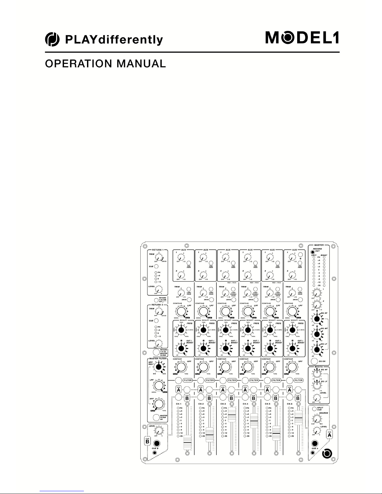
PlayDifferently Model 1 User manual


Limited One Year Manufacturer’s Warranty
Allen & Heath warrants the PLAYdierently branded hardware product and accessories contained in the original
packaging against defects in materials and workmanship when used in accordance with PLAYdierently user manual,
technical specicaons and other PLAYdierently product published guidelines for a period of ONE (1) YEAR from the date
of original purchase by the end-user purchaser ("Warranty Period").
This warranty does not apply to any non-PLAYdierently branded hardware products or any soware, even if packaged
or sold with PLAYdierently branded hardware except for the power supply supplied with the product or as an approved
spare.
Repair or replacement under the terms of the warranty does not provide right to extension or renewal of the warranty
period. Repair or direct replacement of the product under the terms of this warranty may be fullled with funconally
equivalent service exchange units.
This warranty is not transferable. This warranty will be the purchaser’s sole and exclusive remedy and neither
Allen & Heath nor its approved service centres shall be liable for any incidental or consequenal damages or breach of
any express or implied warranty of this product.
Condions of Warranty
The equipment has not been subject to misuse either intended or accidental, neglect, or alteraon other than as described
in the User Guide or Service Manual, or approved by Allen & Heath. The warranty does not cover fader wear and tear. Any
necessary adjustment, alteraon or repair has been carried out by an authorised PLAYdierently distributor or agent.
The defecve unit is to be returned to the place of purchase, an authorised PLAYdierently distributor or agent with proof
of purchase. Please discuss this with the distributor or the agent before shipping. Units returned should be packed in the
original carton to avoid transit damage.
Check with your PLAYdierently distributor or agent for any addional warranty informaon which may apply. If further
assistance is required please contact pdsupport@allen-heath.com
Any changes or modicaons to the equipment not approved by Allen & Heath could void the compliance of the product
and therefore the user’s authority to operate it.
PLAYdierently MODEL 1 complies with the European Electromagnec Compability direcves
2014/30/EU and the European Low Voltage direcves 2014/35/EU .
Any changes or modicaons to the equipment not approved by PLAYdierently could void the compliance of the product
and therefore the users authority to operate it.
MODEL 1 User Guide Issue 1
Copyright © 2016 PLAYdierently. All rights reserved
www.playdierently.org/
Allen & Heath Limited
Kernick Industrial Estate, Penryn, Cornwall, TR10 9LU, UK
www.allen-heath.com

Introduction
MODEL 1 is a 6 channel professional mixer designed for use in the club environment by professional DJs and producers
but is equally at home in a small studio or as a compact outside broadcast desk that does not require microphone inputs.
It is unique in oering six fully featured input channels plus two stereo returns in an industry standard “10” format and
has many features not currently available on any comparable device, such as Input pre-amplier drive control, hybrid
Filter/swept Bell EQ, Dual Cue system, Mixer and Cue linking system, and a fully balanced “Tascam format DB25”
connector system for easy interfacing to external soundcards.
MODEL 1 is a purely analogue mixer and features technology normally found on the nest classic studio desks, such as
a fully balanced mix buss, zero crossing detecon for seamless Filter roung and high voltage dierenal power rails.
MODEL 1 is also internally fully modular.
1
INDEX
Introducon.....................................................................................1
Front Panel Overview.......................................................................2
Return Secon .................................................................................3
Master Filter ...................................................................................4
Main Channel Strip ..........................................................................5
Contour and Sculpt EQ .....................................................................6
Master Secon.................................................................................7
Headphone Cue System ...................................................................8
Drive Control ...................................................................................9
Rear Panel Overview......................................................................10
Rear Panel connecons - Outputs ..................................................11
Rear Panel connecons - Inputs ....................................................12
Mixer linking..................................................................................13
Power Supply.................................................................................15
Block Diagram................................................................................16
Specicaons.................................................................................17

Front Panel Overview
2

Return Section
Descripon
The Return secon is located on the upper le-hand side of the front panel and
consists of two basic stereo channels for use as return inputs from external eects
processors. Connecon to the Return channels is via 4 x 1/4” TRS Jack sockets
mounted on the rear panel, however the Return channels can also be fed from the
DB25 connector DSUB IN 2 - see page 12 for details.
TRIM - Adjusts the level of the return signal. Each Return input pre-amplier is
equipped with a Hard-Limiter circuit and an excess of gain (+28dB) allowing the
return signal to be driven into distoron (as an eect). Turning the Trim control clock-
wise beyond the “0” and into the regain marked “DRIVE” will progressively distort the
signal unl it reaches maximum clipping. See page 9 for more informaon on Drive.
CUE - Routes the pre-level signal to both the Cue A and Cue B monitor systems.
Return Meters - Provides a visual indicaon of each Return signal level. The Peak (PK)
LED will illuminate at signal levels above +8dBu. This is set lower than on the main
channels due to the xed Drive circuit - note that signal levels above PK will acvate
the distoron circuits.
LEVEL - A rotary fader to adjust the amount of the Return signal fed into the main Mix.
RETURN 1-2 LOW CUT - Acvates a lter that aenuates the low frequency response
on both Return 1 and Return 2. The lter has a slope of 6dB per octave and is set at
320Hz (-3dB).
RETURN 1-2 TO MASTER FILTER - This routes both Return 1 and Return 2 to the
Master Filter secon. This switch is controlled by the zero-crossing detecon system
so can be used as a performance eect.
3
Frequency response of Returns with Low Cut switch acve

Master Filter
Descripon
The Master Filter secon consists of a High-Pass Filter (HPF), a Low-Pass Filter (LPF),
and a Resonance control (RES) to adjust the sharpness of the High-Pass lter. Unlike a
Voltage-Control Filter system, (VCF) the lter elements are passive in order to
minimise distoron and eliminate DC voltage breakthrough and because the lter is
passive there is also zero thermal frequency dri. The Master Filter can be used as a
swept frequency performance eect, or as pre-set frequency mix tool to instantly cut
the low or high frequencies of any channel routed to the Filter.
HPF RES - Adjusts the sharpness (Q) of the High-Pass Filter. Set to minimum the HPF
will have a smooth roll o with a low Q. Turning the control clockwise will
progressively increase the Q of the HPF and the gain at the cut-o point - see graph
below for illustraon. Because high Q levels at low frequency can damage the PA
system, high Q sengs are automacally reduced as the HPF control is turned counter
clockwise.
LPF - Progressively aenuates the high frequency content as it is rotated counter
clockwise. A virtually at frequency response up to about 20kHz is achieved with the
control fully clockwise. With the control set fully counter clockwise all frequencies
above 500Hz will be progressively aenuated. The Q of this lter is xed and is not
eected by the resonance control.
HPF - Progressively aenuates the low frequency content as it is rotated clockwise.
A at frequency response down to 30Hz is achieved with the control fully counter
clockwise. With the control set fully clockwise all frequencies below 1kHz will be
aenuated. The Q of this lter is adjusted by the Resonance control.
MASTER FILTER ON - Turns the Master Filter ON. This switch is controlled by the zero-
crossing detecon system so can be used as a performance eect. The zero crossing
system minimises audible clicks and switching arfacts when roung channels to the
Master Filter or switching the lter ON.
4
This graph illustrates how the resonance of the High-Pass Filter is automacally
reduced as the frequency is lowered

Main Channel strip
Descripon
MODEL1 has six idencal main channel strips, each equipped with 2 auxiliary sends,
Input drive control, a unique hybrid EQ lter system, Dual Cues, and a high quality
60mm twin rail fader. The input to each channel is via an RCA connector on the rear
panel, or via the fully balanced DB25 system (see page 12). Channels 3, 4, and 5, are
also equipped with an RIAA pre-amplier for use with turntables.
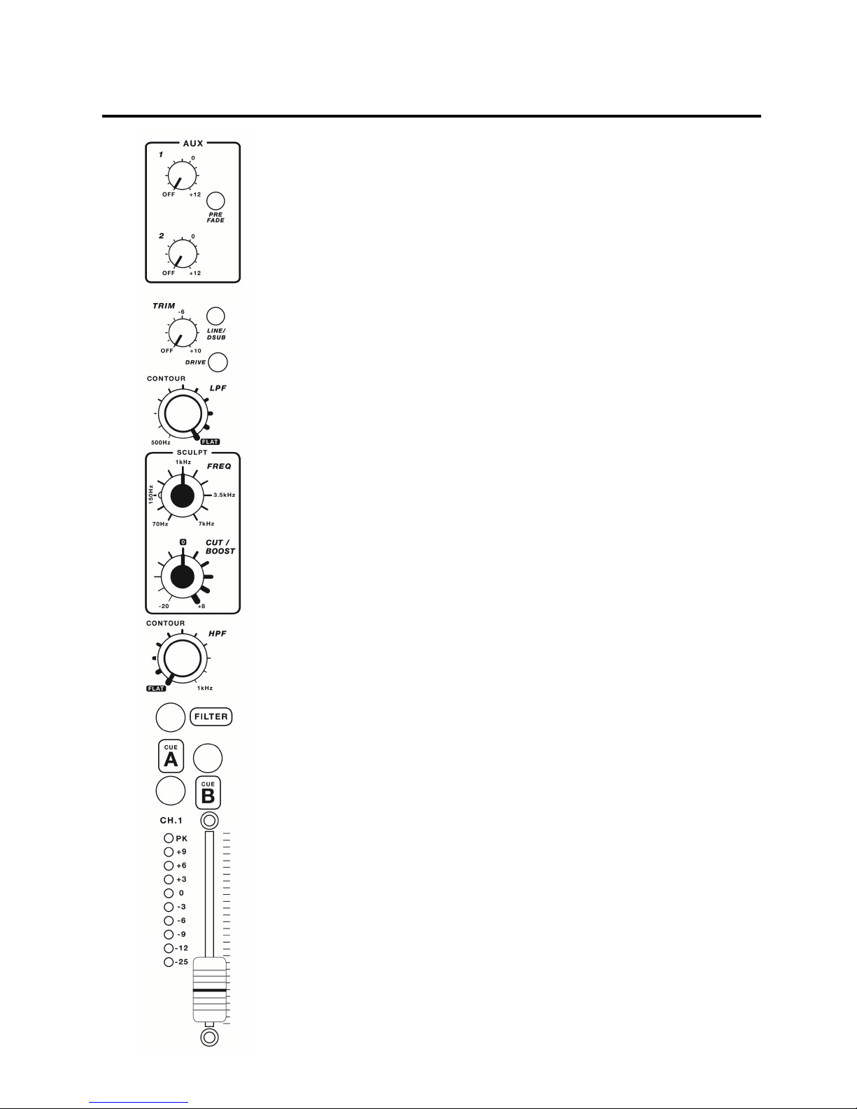
AUX Sends - The two AUX controls send the channel signal to the Auxiliary mix output
jack sockets (and the DB25 Out) for use with external eects processors or, in some
applicaons, local monitors. The PRE FADE switch selects whether AUX 1 sources its
signal Pre or Post the channel fader; default is post fader, (switch up posion). AUX 2
is always post fader, though there is an internal opon to allow AUX 2 to be switched
Pre or Post fader along with AUX 1.
LINE/PHONO/DSUB - This switch selects which input connector the channel signal is
sourced from. The default (switch up posion) sources the signal from its associated
RCA connector on the rear panel. Pressing the switch routes the signal from the DSUB
(DB25) connector system - see page 12. Channels 3, 4, and 5 can be congured for
use with turntables (Phono) by selecng the small red buon on the rear panel,
situated below its associated earth binding post. If this buon is pressed the LINE/
PHONO/DSUB switch cap will glow red, (only in the up posion), to indicate that this
channel has been congured as a turntable input.
DRIVE - This unique control varies the maximum signal level the channel input pre-
amplier can pass (headroom) before it is driven into clipping (distoron). With the
control fully counter clock-wise the channel headroom is unaected, and signal levels
of > +20dBu will remain clean. As the drive control is rotated clockwise input
headroom is progressively reduced, unl at maximum rotaon the pre-amplier will
start to clip at signal levels above –4dBu. The sha of the drive control is illuminated
and will light red to give a visual indicaon of the clip funcon. See page 9 for more
informaon on the drive control.
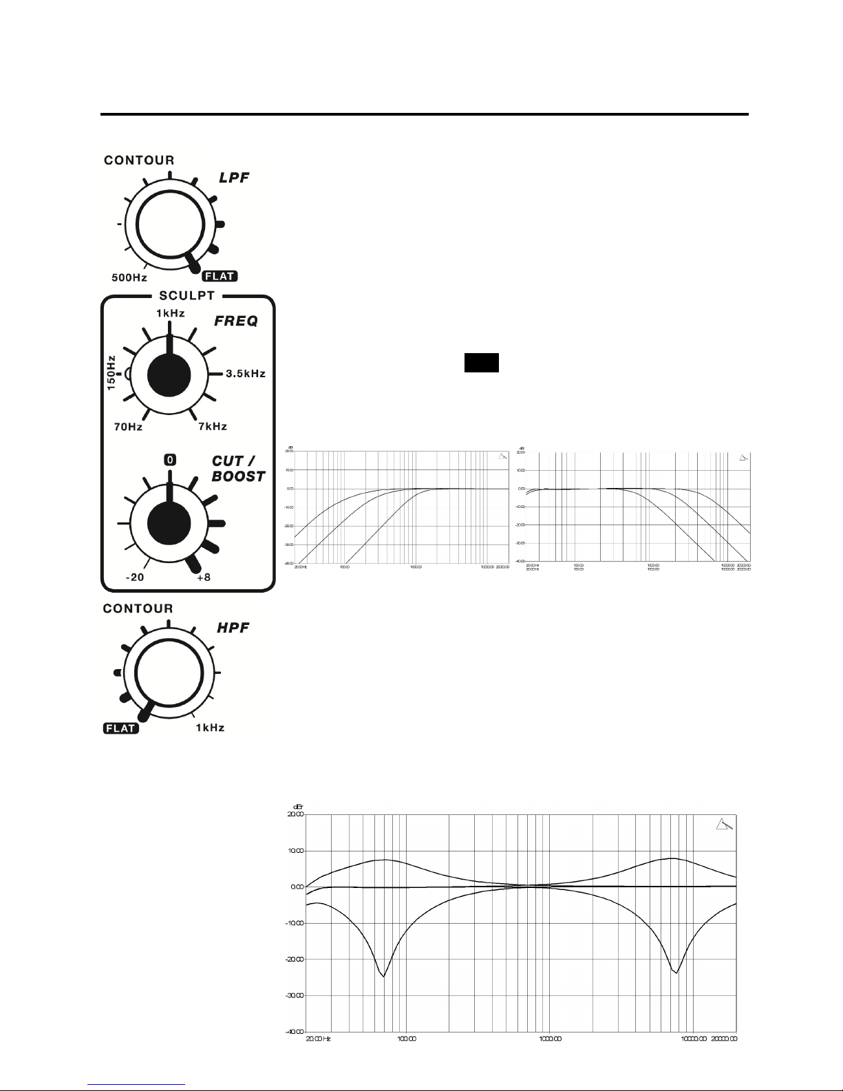
CONTOUR/SCULPT - Unique Hybrid EQ. See page 6 for details.
FILTER - This switch routes the channel signal through to the Master Filter secon, see
page 4 for more informaon on the Master Filter. This switch is controlled by the zero
-crossing detecon system so can be used as a performance eect.
CUE A, CUE B - MODEL 1 is equipped with two independent Cue systems, CUE A and
CUE B. CUE A sends the channel pre-fader, post-EQ, signal to the right headphone
monitor secon, and CUE B to the le headphone monitor. Both Cue systems have an
auto-cancel feature, where selecng one Cue will automacally cancel the previous
selecon.
VCA FADER - The 60mm fader controls the DC level for the channel VCA (voltage
control amplier). These twin rail faders have been carefully chosen to ensure long life
and smooth operaon, and feature a heavy feel for greater precision.
5

Contour and Sculpt
Descripon
MODEL 1 provides a unique alternave to the standard type of xed frequency EQ,
which we feel oers greater creavity and the ability to perform smoother mixes.
Whereas a standard EQ has three or four controls providing cut or boost at a xed
frequency, MODEL 1 ulises a combinaon of high and low pass lters plus a wide
frequency range, swept equaliser, with asymmetric cut and boost.
CONTOUR - As the name implies these two controls allow you to “contour” the
frequency range of the audio signal. They consist of low Q, High-Pass and Low-Pass
lters designed not to add colour to the sound as they are swept across their
frequency range. Due to the low Q , these lters only cut, they do not boost, and are
shown in the posion to a give a frequency response.
The two graphs below illustrate how the frequency response is gently rolled o as
these controls are operated, and show the high degree of out-of-band aenuaon
they oer, cung the high or low frequency content of the audio signal.
SCULPT - “SCULPT” is a semi-parametric swept bell lter, and consist of two controls,
FREQ which sets the centre frequency and CUT/BOOST which adjusts the gain or
aenuaon at this frequency. The level of cut/boost is asymmetric; maximum boost
is limited to +8dB, while the cut is extended to -20dB.
Sculpt has a wide Q and a frequency range that covers almost seven octaves.
The Boost/Cut control is detented in the centre 0 posion to indicate a at frequency
response. The FREQ control isn’t detented and can be swept smoothly across its
range.
6
HPF LPF
FLAT
This graph shows the Cut/Boost response of Sculpt at Max/Min frequency

Master Section
Descripon
The Master secon includes the two Mix level controls, the Master EQ, main buss
metering, record output and the Booth monitor secon.
RECORD OUT - 3.5mm TRS Jack socket feeds the post Master EQ signal as a pre-
fader record output. Nominal level is –6dBu.
LEFT/RIGHT - Two, ten point peak reading LED meters provide visual indicaon of the
mix buss level. Although MODEL 1 has a considerable 28dB of headroom and is
unlikely to suer from clipping due to high signal levels, it is recommended to keep
the average signal level between 0 and +6. Occasional peaks to +9 is acceptable but
operaon with the PK LED ON is best avoided due to the possibility of damaging any
connected PA systems or clipping soundcards, record devices etc.
Play into the red and orange but avoid operang in the white!
MASTER 1, 2 - These controls set the output level for the two main mix outputs.
Master 1 controls the XLR outputs and Master 2 the TRS outputs.
MASTER EQ - Three-Band asymmetric EQ aects all mix outputs, including Booth and
Record. The EQ ON switch is controlled by zero-crossing detecon circuitry which
allows it to be used as a performance eect, as well as a frequency correcon tool.
The response of the Master EQ is shown below.
BOOTH - This secon controls the level and frequency response of the Booth
outputs. The Booth secon incorporates a 2-Band equaliser allowing the user to adjust
the frequency response of the Booth monitors to suit their own preference.
This graph shows the response of the Booth EQ.
7

Headphone Cue system
Descripon
MODEL 1 has two independent Cue systems, A and B. Cue A routes to the right hand
side headphone monitor and the Cue B routes to the le hand headphone monitor.
The dual Cue system makes it much easier for two DJs to perform on the mixer
together as each can select a separate channel to monitor without interfering with the
other performer’s monitoring. This dual system also allows for Cue interacon
between two mixers linked together. See page 13 for details of mixer linking.
Each headphone monitor is equipped with both 1/4” and 3.5mm TRS jack sockets.
CUE A has an auto-cancel funcon, meaning that selecng one channel Cue will
automacally turn o the previous selecon.
CUE B does not auto-cancel, meaning that each channel Cue operates independently
of the other Cue switches.
SPLIT CUE/SOURCE - Split Cue works in conjuncon with the Source control. When
the Split Cue switch is up the Source Control adjusts the level balance between the
Cue and Mix Busses. When the switch is pressed down the Source control pans
between the Cue signal in the le earphone and the Mix signal in the right earphone.
Level - Sets the headphone volume level.
Warning - The headphone ampliers are capable of driving sensive headphones to
very high sound pressure levels (SPL) which could result in permanent hearing
damage!
8
Specicaon
Maximum output power
Headphone A 850mW RMS into 45 Ohms 1kHz
Headphone B 500mW RMS into 100 Ohms 1kHz
Headphone Impedance range 30 Ohms to 150 Ohms

Drive Control
Descripon
MODEL 1 incorporates a unique feature on every input, the Drive control. This control
allows the user to adjust the level at which the channel pre-amplier clips the input signal,
thus creang harmonic distoron as an eect. This is achieved by adjusng the conducon
threshold of circuitry in the feedback loop of the pre-amplier by rotang the “Drive”
control. The Drive control incorporates an LED which illuminates the transparent sha to
indicate when the clip threshold has been reached.
The Drive control and Trim work in combinaon with each other and the amount of
distoron is dependant on several factors; the level of the input signal, the posion of the
Trim and the posion of the Drive. With the Drive control fully counter clockwise the
distoron circuitry is disabled and the channel can be run cleanly well beyond the level at
which the Peak LED lights. With the control fully clockwise, any signal level above
approximately -4dBu will trigger the distoron circuits.
The Drive control is also linked to the channel fader VCA and automacally adds make-up
gain at extreme clip levels, therefore it is normal behaviour for there to be a discrepancy
between the Channel and Master buss metering signal levels. Post –fader level also
inuences brightness of the Drive LED illuminaon.
Fixed level Drive circuitry is built into the Return input pre-ampliers, and can be triggered
by driving the Return signal level beyond that which lights the Peak LEDs
9
Driving the signal level higher results in greater
compression of the signal peaks.
This trace shows the signal level at the clip threshold
with the peaks being slightly rounded or “so clipped”
which will add warmth and strong 2nd harmonics.
This trace shows two signals, one running through the
drive circuit and one not. As the clip threshold has not
been reached, both signals are idencal.
This shows the signal very heavily clipped, virtually to a
square wave.
PRE-AMP
Clip Level
Signal Level

Rear Panel
10

Rear Panel Connections - Outputs
MASTER 1 - Main mix outputs for direct connecon to the system PA.
Balanced XLR, convenonally congured for:
Pin 1 = Ground
Pin 2 = Posive Phase
Pin 3 = Negave Phase
Nominal output level 0dBu, maximum output level +28dBu.
11
MASTER 2 - Secondary mix outputs for feeding a separate zone or PA.
Impedance balanced 1/4” TRS Jack sockets.
Nominal output level 0dBu, maximum output level +23dBu.
BOOTH - Output to the Booth Monion system.
Impedance balanced 1/4” TRS Jack sockets.
Nominal output level 0dBu, maximum output level +23dBu.
AUX 1, 2 - Outputs to external eects units or local monitor system. These signals are also sent
to the DSUB output connector.
Impedance balanced 1/4” TRS Jack sockets.
Nominal output level -2dBu, maximum output level +23dBu.
DSUB OUT - Conforms to the TASCAM DB25 connector standard and allows mulple channels to
be sent fully balanced down a single connector for rapid connecon to external soundcards. The
DSUB Output can also be used to feed the main House PA, bypassing the Mix 1 Level control if
desired.
Balanced TASCAM DB25
Nominal output level +4dBu, maximum level +28dBu.
DSUB OUT Pinout
1 = Mix Le
2 = Mix Right
3 = Aux 1 Le
4 = Aux 1 Right
5 = Aux 2 Le
6 = Aux 2 Right
7 = Cue B Le (Post Level)
8 = Cue B Right (Post Level)
H = Hot (+)
Tip!
DSUB OUT channels 7-8 can be congured as a third FX send using the Cue B phones to adjust the level, and the Cue B Cue
switches to choose the channels to send from.

Rear Panel Connections - Inputs
RETURN 1,2 - TRS Jack inputs for the two Return channels. These Jacks are “normalled” to the
DSUB2 IN connector, therefore if nothing is plugged into these sockets the Returns source their
signal from the DSUB system.
Input impedance = 5K Ohms
Maximum signal input level +23dBu.
12
RCA Inputs - These are the default inputs to all six channels. On channels 3, 4, and 5 these inputs
can be congured for use with turntables by pressing the small red buons located below each
earth binding post. Channels that are congured for turntables (phono) will show the input
selector switch illuminang red.
Input impedance = 5K Ohms
Maximum signal input level +26dBu
DSUB IN 1,2 - Conforms to the TASCAM DB25 connector standard and allows mulple channels
to be sent fully balanced down a single connector for rapid connecon to external Line Level
devices. In a xed installaon these connectors are ideal for connecng mulple CD players,
soundcard etc, leaving the RCA connectors free for guest DJs to use without disconnecng the
House system.
Balanced TASCAM DB25
Nominal input level +4dBu, maximum level +28dBu.
DSUB IN 1 Pinout
1 = Channel 1 Le
2 = Channel 1 Right
3 = Channel 2 Le
4 = Channel 2 Right
5 = Channel 3 Le
6 = Channel 3 Right
7 = Channel 4 Le
8 = Channel 4 Right
H = Hot (+)
C = Cold (-)
G = Ground
PHONO - Press this switch to congure the channel for use with vinyl turntables.
Nominal level 5 - 10mV 1kHz. Maximum input level 108mV 1kHz
Input impedance 47K Ohms. Input capacitance 250pF
DSUB IN 2 Pinout
1 = Channel 5 Le
2 = Channel 5 Right
3 = Channel 6 Le
4 = Channel 6 Right
5 = Return 1 Le
6 = Return 1 Right
7 = Return 2 Le
8 = Return 2 Right

Mixer Linking
MODEL 1 incorporates a unique system that allows mulple mixers to be linked together, either for use with two or
more performers, or as a way to expand the number of channels.
When Linked together the mixers share a common mix buss so only one set of outputs are needed for feeding the PA
and Booth monitors. In addion, the two Cue systems are joined allowing interacve cueing between mulple
performers.
The illustraon below shows a typical link scenario:
13
Connect Link Out on Mixer 2 to Link In on Mixer 1
Performer 1 uses Cue A
Mixer 2Mixer 1
Performer 2 uses Cue B
Mixer 1 feed to Booth Monitors
Mi
Linking two mixers
In this setup Performer 1 and 2 each have their own individual Cue system, but if Performer 1 (using
Cue A) wants to send a Cue signal to Performer 2, they can by selecng a Cue B, and visa versa for
Performer 2.
IMPORTANT! - When linking two mixers together, one will need to be assigned to feed its buss signal through the Link
Cable and on to the main PA and Booth Monitor connected to the other mixer.
In the above diagram it is Mixer 2 that will need to be assigned.
To assign the mixer, turn it over and locate the small 3mm hole underneath the back right hand side rubber foot. Peel
back the foot to expose the hole and using a thin bladed tool, (small screwdriver or similar), press in the switch located
just below the base panel. It is a good idea to check that this switch on the other mixer (Mixer 1) is not selected, i.e.
switched out.
If the mix signal is not being passed through to the other mixer it is likely that this switch has not be
assigned correctly on one of the mixers.
Locaon of assign switch

Mixer Linking continued
In order to link mixers you will need a 9 pin female to female DSUB cable. An inexpensive computer RS232 cable would
probably suce, (as long as it is connected pin 1 to pin1, pin 2 to pin 2 etc.), as all Mix buss connecons are fully
balanced, however for best performance we would strongly recommend using an audio grade cable.
14
LINK OUT Pin connecons 1 = Mix Out Le Hot +
2 = Mix Out Right Hot +
3 = Mix Out Le Cold -
4 = Mix Out Right Cold -
5 = Ground
6 = Cue B IN Right
7 = Cue B IN Le
8 = Cue A OUT Right
9 = Cue A OUT Le
LINK IN Pin connecons 1 = Mix IN Le Hot +
2 = Mix IN Right Hot +
3 = Mix IN Le Cold -
4 = Mix IN Right Cold -
5 = Ground
6 = Cue B OUT Right
7 = Cue B OUT Le
8 = Cue A IN Right
9 = Cue A IN Le

Power Supply
MODEL 1 is powered by an external 90W 24V universal voltage PSU. There are many advantages to powering the
mixer in this way, rstly it frees up internal and rear panel space for extra circuitry for greater funconality in a compact
format, it reduces heat build up inside the mixer, it removes the danger of electrical shock in case of liquid spills, and it
virtually eliminates mains hum elds for beer noise performance. It also allows the addion of a unique feature (on
such a compact mixer) of powering with dual supplies, a feature usually only found on premium live sound and recording
consoles.
Internally, the 24 volts from the external supply, is converted to just under +/- 20V for the analogue power rails using
high frequency switching technology, giving MODEL 1 some of the highest signal headroom of any professional mixer,
irrespecve of its applicaon.
15
The power supply shipped with the MODEL 1 has been carefully selected to
ensure reliable operaon over extended periods, and in most environmental
condions - do not use any other type of supply as it could damage the mixer or
impair its performance.
A single supply is perfectly adequate to power the MODEL 1, and this supply can
be plugged into either PSU 1 or PSU 2 sockets. However in certain applicaons
having a second supply powering the mixer can oer greater security, such as at
a fesval where each supply is powered from separate mains phases. In the
event of one phase going down the other supply will automacally take over
powering the mixer.
When connecng the PSU to the mixer, ensure that the FLAT face of the plug is
towards the le, looking from the rear. Make sure the pins are lined up and
push the plug fully into the socket unl it latches. This is a locking connector
and is released by pulling back the spring loaded sleeve on the plug, which
allows the lock to release. NEVER plug out the connector by pulling on the
power lead as this could damage the locking mechanism.
Make sure the rear panel POWER SWITCH is in the OFF posion before
connecng or disconnecng the power supply.
Correct orientaon of the
power lead connector with
the FLAT facing Le

Block Diagram
16

Specifications 17
Maximum output level +28dBu Balanced, +23dBu Unbalanced
Output Impedance 50R Balanced, 68R Unbalanced
Noise Line in to Line out Unity -90dBu Un-weighted, 22Hz to 20kHz
Residual Noise -100dBu Un-weighted, 22Hz to 20kHz
Dynamic range > 112dB
Frequency Response 20Hz - 40kHz +0/-2dB
Distoron (THD+N) 0.008% Line In to Mix 1 out, 0dBu Unity Gain
Control Aenuaon Beer than 80dB
Inter-channel Crosstalk < -100dB
Le/Right Crosstalk -80dB 1kHz
Maximum Headphone Output 850mW RMS into 45 Ohms (Cue A)
Power consumpon 50W maximum
Weight 5.40kG (Packed 9.10kG)
Dimensions L 37cm x W 32cm x H 11.5cm (Packed L 62cm x W 45cm x H 26cm)
Mixer Dimensions

Other manuals for Model 1
1
Table of contents
Popular Recording Equipment manuals by other brands

Honeywell
Honeywell ERX user manual

360 Systems
360 Systems DigiCart ex E-3000 owner's manual

Aiwa
Aiwa XC-RW500 Service manual

Johnson Controls
Johnson Controls Metasys Integrator MIG3500 Series installation instructions

Stereoping
Stereoping SPRING REVERB manual

Swan Analytical Instruments
Swan Analytical Instruments AMI Option USB Interface V1 Installation instruction