Balluff BNI IOL-302-000-Z026 User manual

BNI IOL-302-000-
Z026
BNI IOL-302-S01-
Z026
User’s G
uide

Balluff Network Interface / IO-Link BNI IOL-302-xxx-Z026
www.balluff.com
1 Notes for the user
1.1
About this guide 2
1.2
Structure of the guide 2
1.3
Typographical conventions 2
1.3.1
Enumerations 2
1.
3.2
Actions 2
1.3.3
Syntax 2
1.3.4
Cross references 2
1.
4
Symbols 2
1.
5
Abbreviations 2
2 Safety
2.1
Intended use 3
2.2
General safety notes 3
2.3
Meaning of the warnings 3
3 Getting started
3.1
Connection overview 4
3.
2
Mechanical connection 5
3.3
Electrical connection 5
3.3
.1
IO-Link interface 5
3.3
.2
Supply voltage connection 5
3.3
.3
Sensor / Actuator interface 6
4 IO-Link interface
4.1
IO-Link data 7
4.2
Process data / Input data 7
4.3
Process data / Output data 8
4.4
Parameter data / Request data 9
4.5
Error 11
4.6
Events 11
5 Technical data
5.1
Dimensions 12
5.2
Mechanical data 12
5.3
Electrical data 12
5.4
Operating conditions 12
5.5
LED indicators 13
Appendix
Product ordering code 14
Order information 14
Scope of delivery 14

Balluff Network Interface / IO-Link BNI IOL-302-xxx-Z026
www.balluff.com
2
1Notes for the user
1.1
About this guide
This guide describes the Balluff Network Interface BNI IOL-302-xxx-Z026 for the application as
peripheral in-/ output module to establish connection of binary standard sensors or actuators. Hereby
it is about an IO-Link device which communicates by means of IO-Link protocol with the
superordinate IO-Link master assembly.
1.2
Structure of the
guide The guide is organized so that the sections build on one another:
Section 2: Basic safety information.
Section 3: The main steps for installing the device.
Section 4: IO-Link, parameter and process data for the device.´
Section 5: Technical data for the device.
1.3
Typographical
conventions The following typographical conventions are used in this guide.
1.3.1
Enumerations
Enumerations are shown in list form with bullet points:
- Entry 1,
- Entry 2.
1.3.2
Actions
Action instructions are indicated by a preceding triangle. The result of an action is indicated
by an arrow.
Action instruction 1.
⇒Action result.
Action instruction 2.
1.3.3 Syntax
Numbers:
−Decimal numbers are shown without additional indicators (e.g. 123),
−Hexadecimal numbers are shown with the additional indicator
hex
(e.g. 00
hex
).
1.3.4 Cross references Cross references indicate where additional information on the topic can be found (see section 5
„Technical data”).
1.4
Symbol
s
Note, Tipp
This symbol indicates general notes.
Note!
This symbol indicates a security notice which must be observed.
1.5
Ab
breviations
BNI Balluff Network Interface
I/O port Standard input / output port
DPP Direct Parameter Page
IOL IO-Link
EMC Electromagnetic Compatibility
FE Function earth
SPDU Service Protocol Data Unit

Balluff Network Interface / IO-Link BNI IOL-302-xxx-Z026
www.balluff.com
3
2Safety
2.1
Intended use
This guide describes the Balluff Network Interface BNI IOL-302-xxx-Z026 for the application as
peripheral in-/ output module to establish connection of binary standard sensors or actuators. Hereby
it is about an IO-Link device which communicates by means of IO-Link protocol with the
superordinate IO-Link master assembly.
2.2
General safety
notes Installation and start up
Installation and start up are to be performed only by trained specialists. Any damage resulting from
unauthorized manipulation or improper use voids the manufacturer’s guarantee and warranty.
The device complies with EMC Class A. Such equipment may generate RF noise. The operator must
take precautionary measures accordingly.
The device must be powered only using an approved power supply (see section 5 “Technical data”).
Only approved cable may be used.
Operating and testing
The operator is responsible for observing local prevailing safety regulations.
When defects and non-clearable faults occur in the device, take it out of service and secure against
unauthorized use.
Approved use in ensured only when the housing is fully installed.
2.3
Meaning of the
warnings Note!
The pictogram used with the word “Caution” warns against a possible hazardous situation
affecting the health of persons or resulting in equipment damage. Ignoring these warnings
can result in injury or equipment damage.
•Always observe the described measures for preventing this danger.

Balluff Network Interface / IO-Link BNI IOL-302-xxx-Z026
www.balluff.com
4
3Getting started
3.
1
Connection
overview
Figure 3-1: Connection overview BNI IOL-302-xxx-Z013
1 Mounting hole
2 Label
3 Supply voltage connection
4 Status LED: communication / module
5 Standard I/O port 1
6 Standard I/O port 3
7 Standard I/O port 5
8 Standard I/O port 7
9 Mounting hole
10 Pin/Port LED: Signal status
11 Standard I/O port 6
12 Standard I/O port 4
13 Standard I/O port 2
14 Standard I/O port 0
15 Status LED: sensors/ actuators supply
16 Status LED: module supply
17 IO-Link interface
18 Ground connection
1
14
13
4
5
6
7
8
9
10
11
12
16
17
18
2
3
15

Balluff Network Interface / IO-Link BNI IOL-302-xxx-Z026
www.balluff.com
5
3 Getting started
3.
2
Mechanical
connection The BNI IOL-302-xxx-Z026 modules are attached by using 2 M6 screws and 2 spacers.
3.3
Electrical
connection
The BNI IOL-302-xxx-Z026 modules require two separate supply voltage connection. The supply
voltage of the module is provided through the IO-Link interface by the host IO-Link Master. The
power for the sensors and actuators is provided by the 7/8” connector.
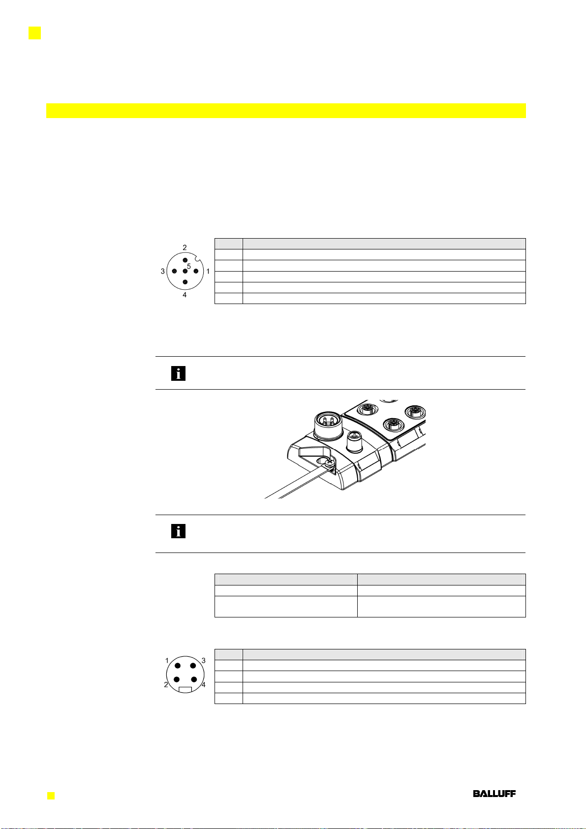
3.3.1 IO-Link interface
IO-Link (M12, A coded, male)
Pin Function
1 Power supply controller, +24V, max 1,1A
2 not connected
3 GND, reference potential
4 C/Q, IO-Link data transmission channel
5 FE, function earth
Connecting the
hub Connection protection ground to FE terminal, if present.
Connect sensor/actuator supply.
Connect the incoming IO-Link line to the hub.
Note:
A standard 3 wire sensor cable is used for connection to the host IO-Link master.
Function earth
Figure 3-2: FE connection
Note:
The FE connection from the housing to the machine must be low-impedance and kept as
short as possible.
Module versions
Hub versions Digital Port
BNI IOL-302-000-Z026 16 In-/ Outputs, configurable
BNI IOL-302-S01-Z026 16 In-/ Outputs, configurable, with single
channel monitoring
3.3.2. Supply voltage Power In (7/8“, male)
connection
Pin Function
1 Power supply actuators, +24V
2 Power supply sensors, +24V
3 GND, Reference potential sensor supply
4 GND, Reference potential actuator supply

Balluff Network Interface / IO-Link BNI IOL-302-xxx-Z026
www.balluff.com
6
3 Getting started
3.3.3 Sensor-Actuator Standard I/O port (M12, A coded, female)
interface
Pin Function
1 +24V, 300mA
2 Input 2 / Output 2
3 GND
4 Input 1 / Output 1
5 FE
Note!
For the digital sensor inputs follow the input guideline per EN61131-2, type 2.
Note!
Outputs: Maximum 2A per output.
Total current of actuator supply is maximum 9A
Note!
Unused I/O port socket must be fitted with cover cap to ensure IP67 protection rating.

Balluff Network Interface / IO-Link BNI IOL-302-xxx-Z026
www.balluff.com
7
4 IO-Link interface
4.1
IO
-
Link d
at
a
BNI IOL-302-000-Z026
Data transmission rate COM2 (38,4 kBaud)
Frame type 1
Minimal cycle time 3 ms
Process data cycle time 12 ms, 3 ms, at minimal cycle time
Process data length 2 Bytes input, 2 Bytes output
BNI IOL-302-S01-Z026
Data transmission rate COM2 (38,4 kBaud)
Frame type 1
Minimal cycle time 3 ms
Process data cycle time 24 ms, at minimal cycle time
Process data length 6 Bytes input, 2 Bytes output
4.2
Proc
ess data
/
Input data
BNI IOL
-
3
02
-
000
-
Z0
26
Byte 0 Byte 1
7 6 7 6 7 6 7 6 7 6 7 6 7 6 7 6
Input 7.0
Input 6.0
Input 5.0
Input 4.0
Input 3.0
Input 2.0
Input 1.0
Input 0.0
Input 7.1
Input 6.1
Input 5.1
Input 4.1
Input 3.1
Input 2.1
Input 1.1
input 0.1
BNI IOL
-
302
-
S01
-
Z0
26
Byte 0 Byte 1
7 6 5 4 3 2 1 0 7 6 5 4 3 2 1 0
Input 7.0
input 6.0
Input 5.0
Input 4.0
Input 3.0
Input 2.0
Input 1.0
Input 0.0
Input 7.1
Input 6.1
Input 5.1
Input 4.1
Input 3.1
Input 2.1
Input 1.1
Input 0.1
Byte 2 Byte 3
7 6 5 4 3 2 1 0 7 6 5 4 3 2 1 0
Short circuit port 7
Short circuit port 6
Short circuit port 5
Short circuit port 4
Short circuit port 3
Short circuit port 2
Short circuit port 1
Short circuit port 0
-
-
-
-
-
Under voltage UA
Untder voltage US2
Under voltage US1
Signal port (x):
x.0: Pin 4,
X.1: Pin 2
Signal port (x):
x.0: Pin 4,
X.1: Pin 2
Short circuit on
port x between
Pin 1 and Pin 3
Short circuit Port x = 1
where
x=0...7

Balluff Network Interface / IO-Link BNI IOL-302-xxx-Z026
www.balluff.com
8
4 IO-Link interface
Byte 4 Byte 5
7 6 5 4 3 2 1 0 7 6 5 4 3 2 1 0
Short circuit Port 7.0
Short circuit Port 6.0
Short circuit Port 5.0
Short circuit Port 4.0
Short circuit Port 3.0
Short circuit Port 2.0
Short circuit Port 1.0
Short circuit Port 0.0
Short circuit Port 7.1
Short circuit Port 6.1
Short circuit Port 5.1
Short circuit Port 4.1
Short circuit Port 3.1
Short circuit Port 2.1
Short circuit Port 1.1
Short circuit Port 0.1
Note:
Actuator short circuit: overload or short circuit of the output signal against 0V.
4.3 P
roc
ess
data
/
Output data
BNI IOL
-
302
-
xxx
-
Z026
Byte 0 Byte 1
7 6 5 4 3 2 1 0 7 6 5 4 3 2 1 0
Output 7.0
Output 6.0
Output 5.0
Output 4.0
Output 3.0
Output 2.0
Output 1.0
Output 0.0
Output 7.1
Output 6.1
Output 5.1
Output 4.1
Output 3.1
Output 2.1
Output 1.1
Output 0.1
Signal port (x):
x.0: Pin 4,
X.1: Pin 2
Actuator short circuit at
Signal port on port x
Short circuit port x.0=Pin4
Short circuit port x.1=Pin2

Balluff Network Interface / IO-Link BNI IOL-302-xxx-Z026
www.balluff.com
9
4 IO-Link interface
4.4 Parameter
data
/
Request data
DPP SPDU Object name Length Range Default value
Index Index Sub-
Index
Identification data
0x07
Vendor ID 2 Byte
read only
0x0378
0x08
0x09
Device ID 3 Byte 0x05070F
0x05070E
0x0A
0x0B
0x10 0 Vendor name 7 Byte BALLUFF
0x11 0 Vendor text 15 Byte www.balluff.com
0x12 0 Product name 20 Byte BNI IOL-302-000-Z026
BNI IOL-302-S01-Z026
0x13 0 Product ID 7 Byte BNI 0050
BNI 0051
0x14 0 Product text 22 Byte Sensor/Actor hub metal
0x16 0 Hardware Revision 1 Byte
0x17 0 Firmware Revision 23 Byte
Parameter data
0x40 0
1-16 Inversion 2 Byte 0-FFFF 0x0000
0x42 0
1-8 Fault state Pin4 2 Byte 0-FFFF 0x0000
0x43 0
1-8 Fault state Pin2 2 Byte
0-FFFF 0x0000
0x44 0
1-16 Power monitoring 2 Byte 0-FFFF -
0x45 0
1-16 Actuator short circuit 2Byte 0-FFFF -
BNI IOL-302-xxx-Z026
Inversion
Byte 0
Byte 1
7
6
5
4
3
2
1
0
7
6
5
4
3
2
1
0
Inversion 7.0
Inversion 6.0
Inversion 5.0
Inversion 4.0
Inversion 3.0
Inversion 2.0
Inversion 1.0
Inversion 0.0
Inversion 7.1
Inversion 6.1
Inversion 5.1
Inversion 4.1
Inversion 3.1
Inversion 2.1
Inversion 1.1
Inversion 0.1
Subindex
16 15 14 13 12 11 10 9 8 7 6 5 4 3 2 1
Inversion port (x):
x.0: Pin 4,
x.1: Pin 2
Inversion
0: normal
1: inverted

Balluff Network Interface / IO-Link BNI IOL-302-xxx-Z026
www.balluff.com
10
4 IO-Link interface
Fault state Pin 4
Byte 0
Byte 1
7
6
5
4
3
2
1
0
7
6
5
4
3
2
1
0
Fault state 3.0
Fault state 2.0
Fault state 1.0
Fault state 0.0
Fault state 7.0
Fault state 6.0
Fault state 5.0
Fault state 4.0
Subindex
4 3 2 1 8 7 6 5
Fault state Pin 2
Byte 0
Byte 1
7
6
5
4
3
2
1
0
7
6
5
4
3
2
1
0
Fault state 3.1
Fault state 2.1
Fault state 1.1
Fault state 0.1
Fault state 7.1
Fault state 6.1
Fault state 5.1
Fault state 4.1
Subindex
4 3 2 1 8 7 6 5
Power monitoring
Byte 0
Byte 1
7
6
5
4
3
2
1
0
7
6
5
4
3
2
1
0
Short circuit Port 7
Short circuit Port 6
Short circuit Port 5
Short circuit Port 4
Short circuit Port 3
Short circuit Port 2
Short circuit Port 1
Short circuit Port 0
-
-
-
-
-
Under voltage UA
Under voltage US2
Under voltage US1
Subindex
16 15 14 13 12 11 10 9 8 7 6 5 4 3 2 1
Actuator short circuit
Byte 0
Byte 1
7 6 5 4 3 2 1 0 7 6 5 4 3 2 1 0
Short circuit
Port 7.0
Short circuit
Port 6.0
Short circuit
Port 5.0
Short circuit
Port 4.0
Short circuit
Port 3.0
Short circuit
Port 2.0
Short circuit
Port 1.0
Short circuit
Port 0.0
Short circuit
Port 7.1
Short circuit
Port 6.1
Short circuit
Port 5.1
Short circuit
Port 4.1
Short circuit
Port 3.1
Short circuit
Port 2.1
Short circuit
Port 1.1
Short circuit
Port 0.1
Subindex
16 15 14 13 12 11 10 9 8 7 6 5 4 3 2 1
Note:
Actuator short circuit: overload or short circuit of the output signal against 0V.
Fault state port (x)
00 – 0
01 – 1
10 – Latest state
11 – Not defined
Fault state port (x)
00 – 0
01 – 1
10 – Latest state
11 – Not defined
Short circuit on
port x between
pin 1 und pin 3
Short circuit port x = 1
Actuator short circuit at
signal port on port x
Short circuit Port x.0=Pin4
Short circuit Port x.1=Pin2

Balluff Network Interface / IO-Link BNI IOL-302-xxx-Z026
www.balluff.com
11
4 IO-Link interface
4.5 Error
Error Code
Additional Code
Device application
error Index not available
0x80 0x11
Device application
error Subindex not available
0x80 0x12
Device application
error Value out of range
0x80 0x30
4.6 Events
Cl
ass / Qualifier
Code ( high + low)
Mode
Type
Instance
Appears Error AL Device Hardware Supply Supply low voltage US1
0xC0 0x30 0x03 0x5000 0x0100 0x0010 0x0002
0xF3 0x5112
Disappears
Error AL Device Hardware Supply Supply low voltage US1
0x80 0x30 0x03 0x5000 0x0100 0x0010 0x0002
0xB3 0x5112
Appears Error AL Device Hardware Supply Supply low voltage UA
0xC0 0x30 0x03 0x5000 0x0100 0x0010 0x0004
0xF3 0x5114
Disappears
Error AL Device Hardware Supply Supply low voltage UA
0x80 0x30 0x03 0x5000 0x0100 0x0010 0x0004
0xB3 0x5114
Appears Error AL Device Hardware Supply Supply low voltage US2
0xC0 0x30 0x03 0x5000 0x0100 0x0010 0x0005
0xF3 0x5115
Disappears
Error AL Device Hardware Supply Supply low voltage US2
0x80 0x30 0x03 0x5000 0x0100 0x0010 0x0005
0xB3 0x5115
Appears Error AL Device Hardware Supply Supply periphery
0xC0 0x30 0x03 0x5000 0x0100 0x0060
0xF3 0x5160
Disappears
Error AL Device Hardware Supply Supply periphery
0x80 0x30 0x03 0x5000 0x0100 0x0060
0xB3 0x5160
Appears Error AL Device Hardware Power Output Stages
0xC0 0x30 0x03 0x5000 0x0400 0x0010
0xF3 0x5410
Disappears
Error AL Device Hardware Power Output Stages
0x80 0x30 0x03 0x5000 0x0400 0x0010
0xB3 0x5410

Balluff Network Interface / IO-Link BNI IOL-302-xxx-Z026
www.balluff.com
12
5Technical data
5.1
Dimensions
Figure 5-1: Dimensions BNI IOL-302-xxx-Z013
5.2 Mechanical
Housing material Die-cast zinc housing
d
at
a
IO-Link port M12, A coded, male
Supply voltage connection 7/8” male, 4 poles
I/O-ports M12, female, 5 poles
Enclosure rating per IEC 60529 IP 67 (only when plugged in and threaded in)
Dimensions (B x H x T in mm) 68 x 181,5 x 32,4
Weight ca. 500 gr.
5.3 Electrical
d
at
a
Supply voltage 18...30.2 V DC, per EN 61131-2
Ripple < 1%
Current draw without load <= 90 mA
5.4
Operating
Operating temperature -5 °C ... 70 °C
conditions
Storage temperature -25 C ... 70 °C
EMC EN 61000-4-2/3/4/5/6 Severity level 2B/3A/4B/2B/3A
Shock/ Vibration EN 60068-2-6, EN 60068-2-27
EN 60068-2-29, EN 60068-2-64

Balluff Network Interface / IO-Link BNI IOL-302-xxx-Z026
www.balluff.com
13
5Technical data
5.5
LED indi
cators
Figure 5-2: Indication LEDs
Status LEDs
BNI IOL-302-xxx-Z013
LED Indicator Function
LED 1 Green / Red Supply module ok / Under voltage
LED 2 Green / Red Supply actuators ok / Under voltage
LED 3 Green / Red Supply sensors ok / Under voltage
LED 4 Green / Green flashing Communication error / Communication ok
LED I/O-ports
standard
Indicator Function LED Pin 2 / Pin 4
OFF Input signal / Output signal = 0
Yellow, static Input signal / Output signal = 1
Red Input port: KS, Short circuit
Output port: Imax, Over-current, Short circuit
Port/Pin LED:
Status input / output
ports
LED 1-4, Status LED

Balluff Network Interface / IO-Link BNI IOL-302-xxx-Z026
www.balluff.com
14
Appendix
Product ordering
code BNI IOL-302-xxx-Z026
Balluff Network Interface
IO-Link Interface
Functions
302 = 16 dig. Inputs/ Outputs
Versions
000 = Standard version
S01 = Single channel monitoring
Mechanical design
Z026 = Die-cast zinc housing, matte nickel plated
Bus connection and power supply: 1xM12 male, external thread
Power supply: 1x7/8“ male, external thread
I/O-Ports: 8xM12, female, 5-poles, internal thread
Order information
Product ordering code Order code
BNI IOL-302-000-Z026 BNI0050
BNI IOL-302-S01-Z026 BNI0051
Scope of delivery BNI IOL… consists of the following components:
•IO-Module
•4 filler plugs M12
•Ground connection-band
•Screw M4x6
•20 Labels
•User’s guide

Balluff Network Interface / IO-Link BNI IOL-302-xxx-Z026
www.balluff.com
15
www.balluff.com
Balluff GmbH
Schurwaldstrasse 9
73765 Neuhausen a.d.F.
Germany
Tel. +49 7158 173-0
Fax +49 7158 5010
Nr.
884703 E •Issue 1107 •Subject to modification
This manual suits for next models
1
Table of contents
Other Balluff Recording Equipment manuals

Balluff
Balluff BNI IOL-106-000-Z012 User manual

Balluff
Balluff BNI IOL-719-002-Z012-C10 User manual

Balluff
Balluff BNI DNT-104-000-Z004 Supplement

Balluff
Balluff BNI IOL-314-S52-P012 User manual

Balluff
Balluff PROFINET BNI PNT-508-055-P067 User manual

Balluff
Balluff BNI PNT-565-W01-K079 User manual

Balluff
Balluff BNI IOL-717-002-E023 User manual

Balluff
Balluff BNI IOW-560-W01-K022 User manual