PLUSLITE ARKIWASH-PL018 User manual

ARKIWASH-PL018 User Manual Page 2
ARKIWASH-PL018
Synopsis
Thank you for purchasing the ARKIWASH-PL018 by Pluslite Products. Every ARKIWASH-PL018 has been
thoroughly tested and has been shipped in perfect operating condition. Carefully check the ship- ping carton for
damage that may have occurred during shipping. If the carton appears to be damaged, carefully inspect your
fixture for any damage and be sure all accessories necessary to operate the unit has arrived intact. In the case
damage has been found or parts are missing, please contact our toll free customer support number for further
instructions. Do not return this unit to your dealer without first contacting customer support.
Introduction: The ARKIWASH-PL018 is a DMX intelligent, IP rated LED par fixture. This fixture can be used in a
stand alone mode or connected in a Master/Slave configuration. This par has multiple operating modes: RGBW
dimmer mode, Static Color mode, Auto Run mode, Color Macro mode, and DMX control. This product is intended to
beusedbyprofessionallytrainedpersonnel only and is not suitable for private use.
These instructions contain important safety information regarding the use and maintenance of this unit. Please keep
this manual with the unit, for future reference.
Caution! There are no user serviceable parts inside this unit. Do not attempt any repairs yourself, doing so will void
your manufactures warranty. In the unlikely event your unit may require service please contact Più39.
PLEASE recycle the shipping carton when ever possible.
⚫
Multi Colors Dimmer
⚫Multi Operating Modes
⚫
Linear Dimming 0-100%
⚫
DMX-512 protocol
⚫
IP65 Locking 3-Pin XLR ConnectionsIn/Out
⚫
Two DMX Modes: 4 Channel Mode, 6 Channel Mode, 8 Channel Mode,40 Channel Mode
⚫Multiple Unit Power Linking
Included:
1 x IP65 Locking Power Cable

ARKIWASH-PL018 User Manual Page 3
ARKIWASH-PL018
Warranty Registration
ARKIWASH-PL018
Installation
ARKIWASH-PL018
Safety Guidelines
The ARKIWASH-PL018 carries a 2 year limited warranty. Please fill out the enclosed warranty card to
validate your purchase. All returned service items whether under warranty or not, must be freight pre-
paid and accompany a return authorization (R.A.) number. The R.A. number must be clearly written on
the out- side of the return package. A brief description of the problem as well as the R.A. number must
also be written down on a piece of paper included in the shipping carton. If the unit is under warranty,
you must provide a copy of your proof of purchase invoice. You may obtain a R.A. number by
contacting our customer support team on our customer support number. All packages returned to the
service department not displaying a R.A. number on the outside of the package will be returned to the
ship- per.
The unit should be mounted using a mounting clamp (not provided), affixing it to the mounting
bracketthatisprovidedwiththeunit.Alwaysensurethat the unitisfirmlyfixedto avoidvibration and
slipping while operating. Always ensure that the structure to which you are attaching the unit is
secure and is able to support a weight of 10 times the unit’s weight. Also, always use a safety cable
that can hold 12 times the weight of the unit when installing the fixture.
The equipment must be installed by a professional, and it must be installed in a place where it is out
of the reach of people’s grasp.
Ensure ALL connections and end caps are properly sealed with a non-conductive dielectric
grease (available at most electrical suppliers) to prevent water ingress/condensation and/or
corrosion
⚫
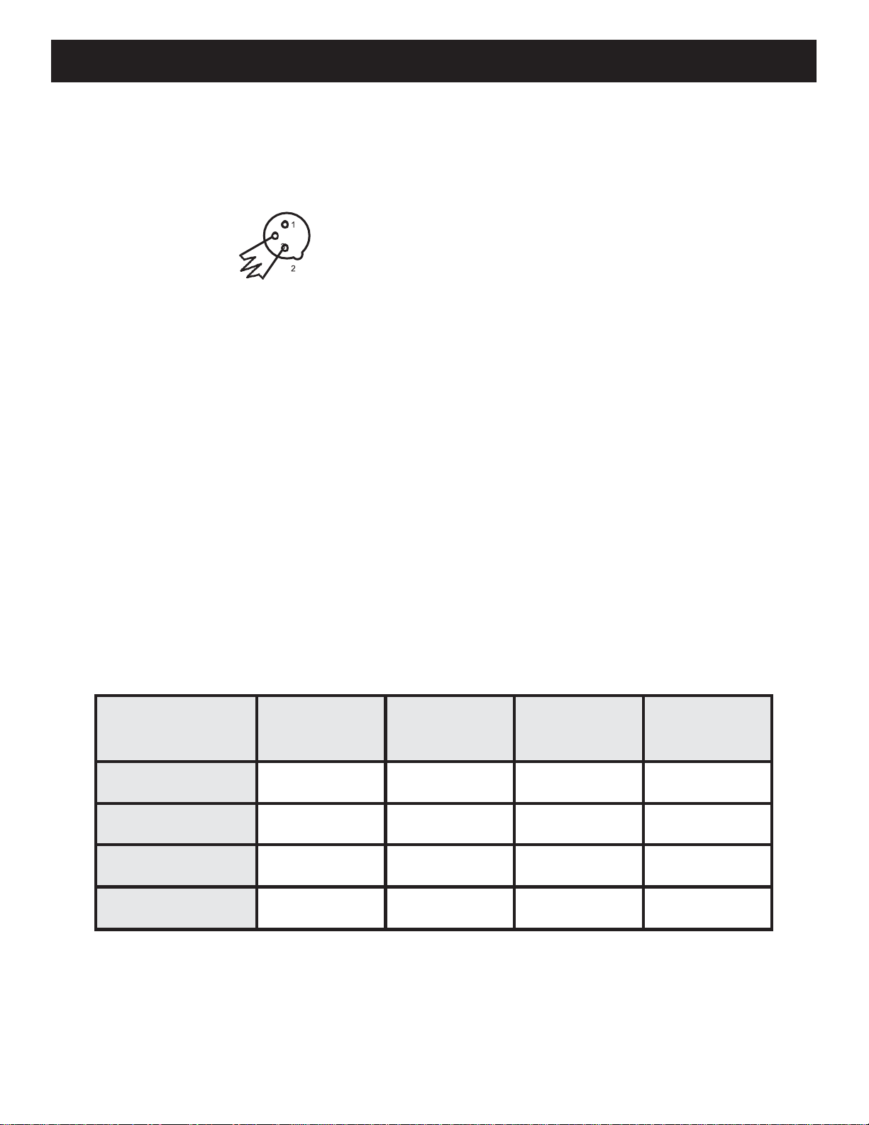
Do not attempt to operate this unit if the power cord has been frayed or broken. Do not attempt to
remove or break off the ground prong from the electrical cord. This prong is used to reduce the risk of
electrical shock and fire in case of an internal short.
⚫
Disconnect from main power before making any type of connection.
⚫
Do not remove the cover under any conditions. There are no user serviceable parts inside.
⚫
Never operate this unit when it’s cover isremoved.
⚫
Never plug this unit in to a dimmerpack
⚫
Alwaysbesuretomountthisunitin anareathatwillallowproperventilation.Allowabout6”
(15cm) between this device and a wall.
⚫
Do not attempt to operate this unit, if it becomes damaged.
⚫
During long periods of non-use, disconnect the unit’s mainpower.

ARKIWASH-PL018 User Manual Page 4
⚫
Always mount this unit in safe and stable matter.
⚫
Power-supplycordsshouldberoutedsothattheyarenotlikelytobewalkedonorpinchedby
itemsplaceduponor againstthem,paying particularattentiontothepointtheyexitfrom theunit.
⚫
Cleaning -The fixture should be cleaned only as recommended by the manufacturer. See page24
for cleaning details.
⚫
Heat -The appliance should be situated away from heat sources such as radiators, heat registers,
stoves, or other appliances (including amplifiers) that produce heat.
⚫
The fixture should be serviced by qualified service personnel when:
A.
The power-supply cord or the plug has been damaged.
B.
Objects have fallen, or liquid has been spilled into the fixture.
C.
The fixture does not appear to operate normally or exhibits a marked change in performance.
D.
The fixture has fallen and/or subjected to extreme handling.

18P Hex IP
IP Notice
ARKIWASH-PL018
IP65 Notice
ARKIWASH-PL018 User Manual Page 5
IP65 RATED
An
IP
rated lighting fixture
is
one, which
is
commonly installed in outdoor
environments and has been designed with an enclosure that effectively
water. The
International Protection (IP)
rating system
is
commonly
expressed as
"IP"
(Ingress Protection) followed by two numbers (i.e. IP65)
where the numbers define the degree of protection. The first digit
(Foreign Bodies Protection) indicates the extent of protection against
particles entering the fixture and the second digit (Water Protection)
indicates the extent of protection against water entering the fixture. An
IP65 rated lighting fixture
is
one, which has been designed and tested to
protect against the ingress of dust (6) and low-pressure water jets from
any direction(5).
MAR
I
NE/COAS
T
AL ENV
I
RONMEN
TI
NS
T
ALLAT
I
ONS!
Please note although this fixture is IP rated, the fixture is NOT suitable for
marine and/or coastal environment installations.
Installing this fixture in amarine
and/or coastal environment may
cause corrosion and/or excessive wear to the
interior and/or
exterior components of the fixture. Damages and/or performance
issues resulting from installation in a marine and/or coastal
environment will
void the manufactures warranty and will NOT be
subject to any warranty claims
and/or repairs.

ARKIWASH-PL018
Layout
ARKIWASH-PL018 User Manual Page 6
ARKIWASH-PL018 back
figure
IP65 Locking Power
Connection In/Out
IP65 Locking Singal
3P Connector In/Out
LCD Display
FUNC button
Up button
Down button
Enter button

DMX Set Up
ARKIWASH-PL018 User Manual Page 7
ARKIWASH-PL018
DMX Set Up
DMX-512: DMX is short for Digital Multiplex. This is a universal protocol used as a form of communication
between intelligent fixtures and controllers. A DMX controller sends DMX data instructions from
the controller to the fixture. DMX data is sent as serial data that travels from fixture to fixture via the
DATA “IN” and DATA “OUT” XLR terminals located on all DMX fixtures (most controllers only have a
DATA “OUT” terminal).
DMX Linking: DMX is a language allowing all makes and models of different manufactures to be
linked together and operate from a single controller, as long as all fixtures and the controller are DMX
compliant. To ensure proper DMX data transmission, when using several DMX fixtures try to use the
shortest cable path possible. The order in which fixtures are connected in a DMX line does not
influence the DMX addressing. For example; a fixture assigned a DMX address of 1 may be placed
anywhere in a DMX line, at the beginning, at the end, or anywhere in the middle. When a fixture is
assigned a DMX address of 1, the DMX controller knows to send DATA assigned to address 1 to that
unit, no matter where it is located in the DMX chain.
Data Cable (DMX Cable) Requirements (For DMX Operation): The ARKIWASH-PL018 can be
controlled via DMX-512 protocol. The ARKIWASH-PL018 has 4 DMX channel modes. The DMX
address is set on the back panel of the ARKIWASH-PL018. Your unit and your DMX controller require a
standard 3-pin XLR connector for data input and data output. We recommend Accu-Cable DMX cables.
If you are making your own cables, be sure to use standard 110-120 Ohm shielded cable (This cable
may be purchased at almost all pro lighting stores).
Notice:
Be sure to follow figures two and three when making your own cables. Do not use the ground
lug onthe XLR connector.Do not connect thecable’s shield conductor to the ground lug or allowthe
shieldconductortocome incontact withtheXLR’s outercasing.Groundingtheshieldcouldcausea
short circuit and erraticbehavior.
DMX512 OUT
3-PIN XLR DMX512 IN
3-PIN XLR
Figure 1
Figure 2
XLR Pin Configuration
Pin 1 = Ground
Pin 2 = Data Compliment (negative)
Pin 3 = Data True (positive)
COMMON
1 DMX + 1
2DMX -
2

DMX Set Up
ARKIWASH-PL018 User Manual Page 8
ARKIWASH-PL018
DMX Set Up
Special Note: Line Termination.Whenlongerrunsof cableareused,youmayneedto useaterminator
on the last unit to avoid erratic behavior. A terminator is a 110-120 ohm 1/4 watt resistor which is connected
between pins 2 and 3 of a male XLR connector (DATA + and DATA -). This unit is inserted in the female
XLR connector of the last unit in your daisy chain to terminate the line. Using a cable terminator will
decrease the possibilities of erratic behavior.
Termination reduces signal errors and
avoids signal transmission problems
and interference. It is always advisable
to connect a DMX terminal, (Resistance
120 Ohm 1/4 W) between PIN 2 (DMX-)
and PIN 3 (DMX +) of the last fixture.
Figure 3
All fixtures should be given a DMX starting address when using a DMX controller, so the correct fixture
responds to the correct control signal. This digital starting address is the channel number from which
thefixturestartsto“listen” tothedigitalcontrolsignalsentoutfromtheDMXcontroller.Theassignment of this
starting DMX address is achieved by setting the correct DMX address on the digital control display on
thefixture.
You can set the same starting address for all fixtures or a group of fixtures, or set different addresses
for each individual fixture. Setting all fixtures to the same DMX address will cause all fixtures to react in
the same way, in other words, changing the settings of one channel will affect all the fixtures
simultaneously.
If you set each fixture to a different DMX address,each unit willstart to “listen” to the channel number you
have set, based on the quantity of DMX channels of each fixture. That means changing the settings of one
channel will only affect the selected fixture.
In the case of the ARKIWASH-PL018, when in 8 channel mode you should set the starting DMX
addressof the first unit to 1, the second unit to 9 (8 + 1), the third unit to 17 (8 + 9), and so on. (See chart
below for more details.)
Channel Mode
Unit 1
Address
Unit 2
Address
Unit 3
Address
Unit 4
Address
4 channels
1
5
9
13
6 channels
1
7
13
19
8 channels
1
9
17
25
40 channels
1
41
81
121

ARKIWASH-PL018
DMX Traits & Values
ARKIWASH-PL018 User Manual Page 9
4CH
describe
parameter
CH1
R dimmer 0-100%
0~255
CH2
G dimmer 0-100%
0~255
CH3
B dimmer 0-100%
0~255
CH4
W dimmer 0-100%
0~255
6CH
describe
parameter
CH1
Main Dimmer
0~255
CH2
R dimmer 0-100%
0~255
CH3
G dimmer 0-100%
0~255
CH4
B dimmer 0-100%
0~255
CH5
W dimmer 0-100%
0~255
CH6
Dimmer Mode
Macro 1
Macro 2
Macro 3
……
Macro 16
0~15
16~31
32~47
48~63
……
240~255
10CH
describe
parameter
CH1
Main Dimmer
0~255
CH2
Strobe Speed(slow->fast)
0~255
CH3
Dimmer Mode
Auto Mode1
Auto Mode2
Auto Mode3
……
Auto Mode24
0~10
11~20
21~30
31~40
……
241~250

ARKIWASH-PL018
DMX Traits & Values
ARKIWASH-PL018 User Manual Page 10
Sound Mode
251~255
CH4
Mode Speed
0~255
CH5
R dimmer 0-100%
0~255
CH6
G dimmer 0-100%
0~255
CH7
B dimmer 0-100%
0~255
CH8
W dimmer 0-100%
0~255
40CH
describe
parameter
CH1
R1 dimmer 0-100%
0~255
CH2
G1 dimmer 0-100%
0~255
CH3
B1 dimmer 0-100%
0~255
CH4
W1 dimmer 0-100%
0~255
CH5
R2 dimmer 0-100%
0~255
CH6
G2 dimmer 0-100%
0~255
……
……
……
CH39
B10 dimmer 0-100%
0~255
CH40
W10 dimmer 0-100%
0~255

ARKIWASH-PL018
System Menu
ARKIWASH-PL018 User Manual Page 11
Software Version < V1.05
Note 1: In FAN AUTO mode, when the temperature is above 50°, the fan will automatically start cooling until
it drops below 50°
Note 2: Press ENTER to save the data and press and hold to see the current lamp board temperature
LCD Display
describe
parameter
Mode:DMX
Addr:001
DMX Mode/Master-Slave
Mode/DMX Address Set
1~512
Mode:CH
04CH
DMX Mode/Master-Slave
Mode/DMX Channels Set
4/6/8/40
Mode:Led
Mode:01
Led Effect Mode
1~24
Mode:SP
Mode:70
Led Effect Mode Speed
0~99
Mode:BE
Sound:15
Sound Mode
0~20
Mode:Dim
LedR:255
R Dimmer
0~255
Mode:Dim
LedG:255
R Dimmer
0~255
Mode:Dim
LedB:255
R Dimmer
0~255
Mode:Dim
LedW:255
R Dimmer
0~255
Mode:ST
Speed:0
Strobe Speed(slow->fast)
0~99
Mode:Fan
AUTO
FAN SET
AUTO/OPEN/CLOS
E

ARKIWASH-PL018
Pixel Zone Control
ARKIWASH-PL018 User Manual Page 12
ARKIWASH-PL018
Master-Slave Configuration
FUNCTION : Mode Setting Key
UP :Parameter Settings Key.parameters add
DOWN : Parameter Settings Key. parameters sub
ENTER : Data Save Key, temperature display
Master-Slave Configuration:
This function will allows you to link units together to run in a Master-Slave set-up. In a Master-Slave
set up one unit will act as the controlling unit and the others will react to the controlling units built-in
programs. Any unit can act as a Master or as a Slave however, only one unit can be programmed to
act as the “Master.”
Master-Slave Connections and Settings:
1.
Daisy chain your units via the XLR connector on the rear of the unit. Use standard XLR data cables
to link your units together. Remember that the Male XLR connector is the input and the Female
XLR connector is the ouput. The first unit in the chain (master) will use the female XLR connector
only. The last unit in the chain will use the male XLR connector only.
2.
Connect the first “Slave” unit to the“Master.”

ARKIWASH-PL018
Pixel Zone Control
ARKIWASH-PL018 User Manual Page 13
This fixture features pixel zone control. See the diagram below, which illustrates the specific pixel
zone set up
Pixel 1
Pixel 1
Pixel 10

Dimmer Mode Chart
ARKIWASH-PL018 User Manual Page 14
ARKIWASH-PL018
Dimmer Curve Chart
ARKIWASH-PL018
Dimmer Mode Chart
DIMMER
100%
50%
10%
0%
0 Sec
Dimming Mode
Ramp Effect
0 sec Fade Time
1 sec Fade Time
255
0
255
0
Rise Time (ms)
Down Time (ms)
Rise Time (ms)
Down Time (ms)
Standard (default)
0
0
0
0
Stage
780
1100
1540
1660
TV
1180
1520
1860
1940
Architectural
1380
1730
2040
2120
Theatre
1580
1940
2230
2280
Time
(ms)
Rise
Time
Down
Time

ARKIWASH-PL018
Dimensional Drawing
ARKIWASH-PL018 User Manual Page 15
*NOT TO SCALE

Technical Specifications
ARKIWASH-PL018 User Manual Page 16
ARKIWASH-PL018
Trouble Shooting
ARKIWASH-PL018
Cleaning
ARKIWASH-PL018
Multiple Unit Power Linking
With this feature you can connect the fixtures to one another using the power input and out
-
put sockets. The maximum that can be connected is 8 fixtures @ 120V and 15 fixtures @ 240V.
After the maximum connected fixtures you will need to use a new power outlet.
NOTE: USE CAUTION WHEN POWER LINKING OTHER FIXTURES TO THE ARKIWASH-PL018
AS THE
POWER CONSUMPTION OF OTHER LIGHTING FIXTURES WILL VARY!
Listed below are a few common problems the user may encounter, with solutions.
Unit not responding to DMX:
1. Check that the DMX cables are connected properly and are wired correctly (pin 3 is “hot”; on
some other DMX devices pin 2 may be ‘hot’). Also, check that all cables are connected to the right
connectors; it does matter which way the inputs and outputs are connected.
Due to fog residue, smoke, and dust cleaning the internal and external optical lenses must be car-
ried out periodically to optimize light output.
1.
Use normal glass cleaner and a soft cloth to wipe down the outside casing.
2.
Clean the external optics with glass cleaner and a soft cloth every 20 days.
3.
Always be sure to dry all parts completely before plugging the unit back in.
Cleaning frequency depends on the environment in which the fixture operates (i.e. smoke, fog resi-
due, dust, dew).

Technical Specifications
ARKIWASH-PL018 User Manual Page 17
Model: ARKIWASH-PL018
Voltage:
LEDs:
IP Rating:
Working Position:
Power Draw:
Power Linking:
Weight:
Dimensions:
Colors:
DMX Channels:
Warranty:
100V ~ 240V/50~60Hz
40 x 12W 4-in-1 CREE LED’s
IP65
Any safe working position
400W
8 Fixtures
Max.@120V
15 FixturesMax.@240V
12Kgs.
466 x 123 x 338mm
RGBW Color Mixing
4 DMX Modes,6 Channel Mode,
8 DMX Modes,40 Channel Mode
2 Years
ARKIWASH-PL018
Multiple Unit Power Linking
Please Note: Specifications and improvements in the
design of this unit and this manual are subject to change
without any prior written notice
https://www.piu39av.com/pluslite-lighting/
Table of contents
Popular Light Fixture manuals by other brands

AVE
AVE ECLIPSE CLUB 1000MKII user manual

Philips
Philips 6910104PH Instruction leaflet

Westfalia
Westfalia 90 05 36 Original instructions

Inter-lux
Inter-lux Sattler Sky Assembly instruction

Elgo
Elgo HERMETIC ECO 120-2 Installation and operating manual

Lucci LEDlux
Lucci LEDlux 229150 installation instructions

Anslut
Anslut 423-260 Assembly instructions

Larson Electronics
Larson Electronics EPL-WPLED-100W-RT instruction manual

FONESTAR
FONESTAR MOV-18L instruction manual

Lightolier
Lightolier SL301A specification

Chauvet
Chauvet LX 5 Quick reference guide

Cooper Lighting
Cooper Lighting Metalux Micro-Bay Luminaire Brochure & specs