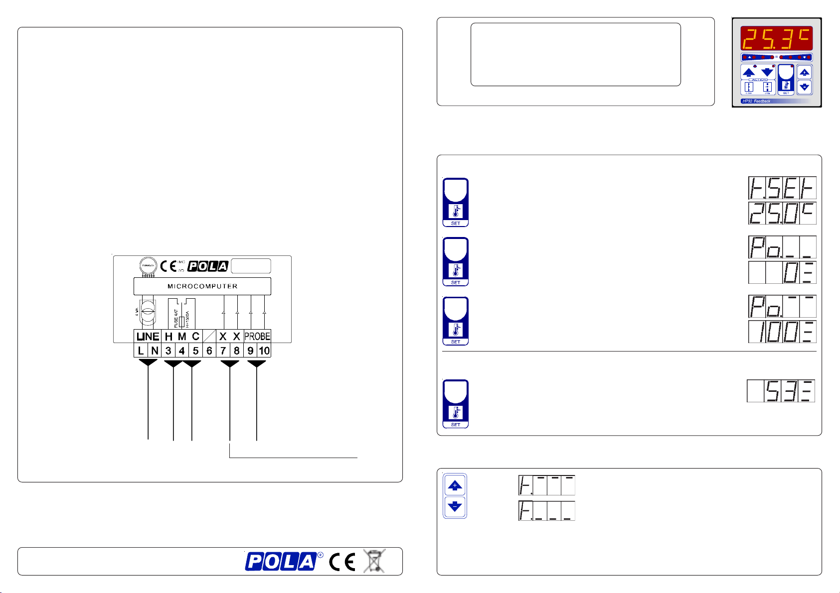
PRESET PROGRAMS (Bootstrap)
This processor is already programmed with the following (variable) settings.
To return to these settings at any time you may:
Power off the processor, press SET key and keep it pressed giving power on:
boot message will be displayed (release now SET key).
t.SEt=25.0° Po._ _= 0 Po.- -=100 .
The COSt values are shown in COSt Programming
*1) For more details see Operative Diagram.
*2) Reached SET temperature (SET key in Run Mode) flap position is that value (0is
fully closed).
*3) If swing occurs when searching for the position during flap operation (due to
mechanicalgearmotorhisteresis),itraisesthePcn.1settingvalueuntiliseliminated.
*4)Thatvalues canbeenteredinmanualorautomaticmodeareset byInitprocedure.
*5) tEnP =0 : °C Temperature range.
tEnP =1 : °F Temperature range.
*6) You can correct the readings on the various sensors (+ or -).
COSt PROGRAMMING (System constants)
t.SEt. with Pct.1=0
100
90
80
70
60
50
40
30
20
10
0
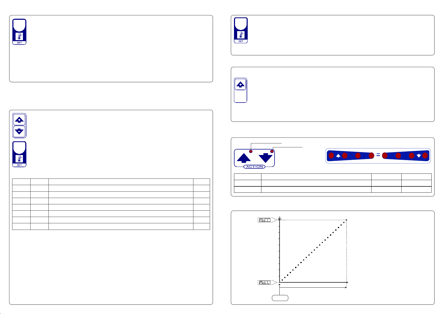
OPERATIVE DIAGRAM
ProP °Ambient temperature
% Opening Flap
FLAP POTENTIOMETER INITILIZATION PROCEDURE (Init)
Connectthepotentiometerofanyvalue(max10Kohm,recommended1Kohm).
It must be applied to the flap motor.
Having done this, proceed as follows to record the potentiometer values.
Press SET key for at least 5 seconds: when Init message will be displayed for
more than one second release SET key. HP32 closed the flap (light CLOSE
flashes) and the potentiometer resistance value is displayed.
Whentheflaphavecompletelyclosed,pressSETtorecordthevalue:atthispoint HP32
openstheflap(lightOPENflashes)andthepotentiometerresistancevalueisdisplayed.
When the flap have completely opened, press SET to record the value.
HP32 then returns automatically to the Run mode.
.sseM eulaV gninaeM etoN
PorP °0.4 egnarlanoitroporPC° 1*
1.tcP 0TESotpalfnoitisoP% 2*
1.ncP 5egnarlartueN% 3*
LC.oP 0noitisopdesolcpalfnirotsiserretemoitnetoP 4*
PO.oP 9999 noitisopnepopalfnirotsiserretemoitnetoP 4*
PnEt 1= noitatneserpererutarepmeT 5*
Et.dA °0.0 )-ro+(noitcerrocerutarepmetrosnesC° 6*
These settings refer to the operation mode of the system and must be made on
initial startup. Press - / + at the same time for at least one second: the message
C.O.S.t. will be displayed.
Press than repeatedly SET until the message regarding the chosen variable is
displayed (see table below) : value of variable and message will be displayed.
Press + or - to set a new value and then press SET to confirm.
The next system constant will then appear.
You can press SET for at least 2 seconds to exit and return to the Run Mode.
In some start-up conditions may be useful to work in "manual" mode:
Powerofftheprocessor,press + keyandkeepitpressedgivingpoweron:HAnd
message will be displayed (release now + key).
Push + until is displayed number required to be handed (see table) and push
SET for activing relay.
Pushing again + for increase relay number previous relay is disactivated.
You can press SET key for a least two seconds to escape and return to the
Run Mode.
MANUAL MODE
STATUS INDICATION LAMPS
Lamp. Meaning N°Relay Contatcts
CLOSE Close (Heat) On 1 3-4
OPEN Open (Cool) On 2 4-5
ON OPEN (COOL)
ON CLOSE (HEAT)
Swinging Ambient / Set temperature (t.SEt) indicator