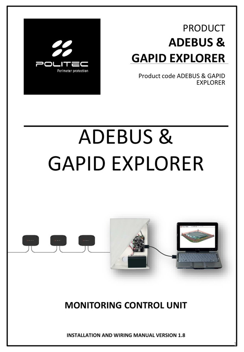
Politec ADEBUS User manual

PRODUCT
ADEBUS
ADEBUS
Product code ADEBUS
MONITORING CONTROL UNIT
INSTALLATION AND WIRING MANUAL VERSION 2.1
1

Table of contents
2
ADEBUS
1.Introduction…………………………………………………………………………………………........................................4
2.Product description…………………..………………………………………………………….………………………….…..4
3.General warnings…………………………………………………………………………………………………………………...….5
3.1 Additional warnings for devices powered by mains voltage
3.2 Installation warnings
4.List of main components………….………………………………………………………………………………………………..6
4.1 The control unit
5.Description of the boards ………………………………………………………………………………………………………… 7
5.1 ADEBUS SC - Adebus motherboard
5.2 ADEBUS ESP - Expansion board with 16 relay outputs for Adebus
5.3 ALPO2B
6.Preparation for installation ………………………………………………..…………………………………………………....10
6.1 Preparing the components before installation
6.2 It is advisable to carry out
7.Connections……………………………………………………………………………..…................................................12
7.1 Adebus internal connections
7.2 Barrier connections - Adebus
7.3 Examples of cable connections
8.Installation and first access - DEFAULT STATIC IP 192.168.1.222 …………..…………………………….....13
8.1 Access via Ethernet port
8.2 Factory settings
8.3 Adebus Explorer software installation and start-up
8.4 Main screen
8.5 Working Path
8.6 Site Creation
8.7 Configuration Mode
8.8 Address Setup
8.9 System Configuration
8.10 Adding or replacing barrier
8.11 Popup
9.Access to the columns - Adebus Explorer ……………………………....………..……………………………........ 18
9.1 Key
9.2 Column Detail
9.3 New Configuration
9.4 Input/Output Associations
9.5 Polarity
10.Events archive …………………....……………………………………………………..............................................21
POLITEC | INSTALLATION MANUAL - VER.2.1

Table of contents
3
ADEBUS
11.Appendix A - WEB page .………………………. ………………………. ………… ..… .. .22
11.1 Column Detail
11.2 Column Status
11.3 Output Configuration / Output Polarity
11.4 Network Configuration
12.Appendix B - configuration and barrier statuses ……………………………….… .. …… .24
12.1 Status
12.2 Analogue Values
12.3 Configuration
13.Appendix C - Special Input …………………………………………………… ..…………………………………………… ..... 27
13.1 Connection in barrier
13.2 Enabling and software status
13.3 Output configuration
14.Appendix D - Sectioning ….…………… .. ……………………………………………… ..... 29
14.1 Enabling in pairs - Sectioning
14.2 Area configuration - Sectioning
14.3 Software configuration - Sectioning
15.Technical characteristics …………….……………………………………………. ………… .30
16.Product disposal ………….………………. …………………………………. ……….….…. ..31
POLITEC | INSTALLATION MANUAL - VER.2.1

MAX 1 Km MAX 1 Km
MAX 32 Columns
1.Introduction
4
ADEBUS POLITEC | INSTALLATION MANUAL - VER.2.1
Congratulations on having purchased the Politec monitoring control unit.This appliance
guarantees long-lasting and reliable operation if installed correctly.For correct and effective use,
it is necessary to read this instruction manual carefully.
The barriers and the monitoring control unit have been designed to detect intrusions
and activate the alarm; it is not a device that prevents intrusion.Politec is not
responsible for damage, injury or loss caused by accidents, theft, force majeure
(including momentary lightning-induced overcurrent), abuse, improper or incorrect
use, faulty installation or inadequate maintenance.
2. Product description
ADEBUS is a monitoring control unit
for the management of up to 32
columns (MANA SMA, PARVIS MES
SMA, SANDOR PLUS SMA) divided
arbitrarily into 2 branches
(expandable) using both the serial
ports Com0 and Com1.Adebus
manages, supervises and configures
every individual column reachable
through a TCP/IP connection.
This system is ideal for managing
the perimeter protection of large
areas.
The main features of this system
are:
•Each column and beam can be
configured and verified in real
time: all operations can be
performed locally or remotely via
WEB;
•Configuration of each relay
output associated with any
event.
•Storing and downloading up to
32000 events on aPC.
Warnings
Mounting, installation of the barrier and connection to the mains must be carried out
by expert and qualified personnel, in compliance with rules and regulations applicable
to electrical systems.

3.General warnings
5
ADEBUS
This installation manual contains important information regarding safety for installation: it is
necessary to read all the instructions before proceeding with the installation.
Keep this manual for future use.
•If you have any questions or doubts during installation, do not carry out any operations and contact
the support service.
•Use of these products for purposes other than those specified in these instructions is prohibited.
•You must not make any change to the components of the product unless stated in the manual in
order not to void the warranty; such operations can only lead to malfunctions; Politec assumes no
liability for malfunctions or damage due to modified products.
•Depending on the specific situation of use, check for the need for additional devices: detectors or
signalling devices.
•During installation, mounting and use of the product, make sure no foreign objects (solids, metals
or liquids) are able to penetrate inside the open devices.
•Manufacturer's liability:Politec assumes no liability for failures resulting from incorrect installation;
lack of maintenance, incorrect assembly or use.
•Politec is also not liable for incorrect or incomplete operation of the product or failure to detect
intrusion.
•Warranty (summary of conditions):Politec guarantees its products for a period of 2 years from the
production date.The warranty is applied to those purchasing directly from Politec; there is no
warranty for the end user who, in the event of breakdowns or faults, must contact the installer or
dealer.
•The warranty excludes aesthetic parts as well as parts subject to normal wear and parts subject to
normal consumption such as batteries and accumulators.
3.1 Additional warnings for devices powered by mains voltage
This manual is intended only for technical personnel qualified to install such devices.
•Assessing the hazards that may occur during installation and use of the system, in order to achieve
complete safety, it is necessary that installation takes place in full compliance with applicable laws,
methods, rules and regulations.
•Before accessing the internal terminals of the product, it is necessary to disconnect all the power
circuits.
•If automatic circuit breakers or fuses trip, before resetting them it is necessary to identify the fault
and repair it.
3.2 Installation warnings
•Check that all the material to be used is in excellent condition and suitable for use.
•Before proceeding with the installation, check the environmental class of the products in the
"technical specifications" chapter.
•Check, by comparing with the values shown in the paragraph "technical specifications".
•Do not place the system components close to heat sources as they could be damaged.
•Each product has its own operating principle: check the instructions for choosing the right position
in the respective instruction manual.
POLITEC | INSTALLATION MANUAL - VER.2.1

N
o.
COMPONENT CODE
DESCRIPTION
1
ADEBUS
Adebus motherboard
2
ADEBUS ESP
Expansion board with 16
relay outputs
3
ADEBUS S2 BOARD
4
TRANSF
LAR22S
18/24 Vac transformer
5
ALPO2B
Power supply board
6
BATTERY (not
included)
17 Ah Battery
compartment
7
TAMPER
6
ADEBUS
4.1 The control unit
The box contains the following components and accessories.
When opening the package, check that everything has been included.
POLITEC | INSTALLATION MANUAL - VER.2.1
4
6
1
7
4.Main components list
2
5
3

No
.
COMPONENT
1
Serial input line COM0
2
Serial input line COM1
3
0
-12 Vdc input
4
LAN socket
5
Relay outputs block
6
Inputs
7
Relay expansion connection
8
RS485
Adebus S2 board
7
ADEBUS
5.1 ADEBUS SC - Adebus motherboard.
Control board, to which RS485 is connected for barriers, Adebus Esp and LAN port
POLITEC | INSTALLATION MANUAL - VER.2.1
1
3
5
2
4
6
7
8
5.Board Description

8
ADEBUS
5.2 ADEBUS ESP - Adebus ESP Relay board
Interface board between configured relay outputs and universal alarm control unit
POLITEC | INSTALLATION MANUAL - VER.2.1
4
5
3
1
2
No.
COMPONENT
1
0
-12 Vdc input
2
Relay outputs block 1
-8
3
Output connector to next
expansion board
4
Relay outputs block 9
-16
5
Input connector from CA 230
motherboard
6
Input connector from previous
expansion board
6

No
.
COMPONENT
1
18 Vac input
2
24 Vac input
3
24 Vac output
4
0
-13.8 Vdc outputs
5
Battery 12V
- 17Ah output
6
Signalling outputs
7
10 A fuse (24 Vac)
8
3 A fuse (12 Vac)
9
ADEBUS
5.3 ALPO2B - Power supply board.
POLITEC | INSTALLATION MANUAL - VER.2.1
1
5
6
3
4
7
8
2

6.Preparation for installation
10
ADEBUS
6.1 Preparing the components before installation
Since the communication between the barriers and the monitoring control unit takes place by wire, it
is advisable to firstly check that all the parts of the control unit and sensors and any accessories are
present before beginning the installation.
6.2 It is advisable to carry out in the following ORDER:
•The installation of the control unit application on a PC
•The assembly and wiring of the barriers on the perimeters to be protected;
•Alignment and functional verification of all barriers in the field without the use of software;
•Taking note of the serial numbers of the individual barriers;
•Site creation from Adebus Explorer software;
•Barrier addressing;
•System start-up via WEB page, System Configuration menu and individual column flags;
•Adebus output configuration;
•Barrier configuration;
Before proceeding with the installation, it is necessary to check the integrity of the product, the
adequacy of the model chosen and the suitability of the environment intended for installation:
• Check that all conditions of use fall within the "limits of use" and in the "Technical specifications of
the product".
• Check that the environment chosen for the installation is compatible with the total footprint of the
product.
• Check that the surface chosen for the installation of the product is solid so as to ensure stable fixing
and that it is adequately protected from possible impacts or atmospheric agents.
POLITEC | INSTALLATION MANUAL - VER.2.1

7.Connections
ADEBUS
7.1 Adebus internal connections
It is necessary to make the power supply connections for all the boards present, Adebus SC and
Adebus ESP respecting the polarity.Also check the connection between the Adebus board and Adebus
ESP
POLITEC | INSTALLATION MANUAL - VER.2.1
+12Vdc
7.2 Adebus- barrier connections
Connect the columns to the Adebus SC board using the dedicated shielded double twisted cable.It is
mandatory to connect the synchronism cables between one column and another for the barrier to
work correctly. MES9C board Barrier 1 MES9C board Barrier 2
Adebus board
Braid
Green
White
Red
Black
11
In the example,
synchronism is
connected via a red-
black cable, the BUS
signal on a green-white
cable, the braids
positioned in the
negative

7.3 Examples of cable connection
Up to 2 branches of serial bus can be used.The RS485 bus must not be connected in a star-shaped
manner and the loop must never be closed.Synchronism will be a closed loop if and only if the barriers
form a closed perimeter protection.
ADEBUS POLITEC | INSTALLATION MANUAL - VER.2.1
12
ADEBUS
ADEBUS
ADEBUS
ADEBUS
ADEBUS
ADEBUS
synchronism
bus
RS485 CABLE MANA SMA
E.g.Synchronism
connects all the
columns in a
loop.Bus connects
Adebus and all
the columns
E.g.Synchronism
connects all the
columns.Bus
connects Adebus
and all the
columns
E.g.Synchronism
connects all the
columns.Bus
connects Adebus
and all the
columns

8.Installation and first access - DEFAULT STATIC IP 192.168.1.222
13
ADEBUS
8.1.Access via Ethernet port.
The ADEBUS system is managed via a LAN port with a static IP address.The system can be accessed
remotely by activating the public IP address and opening the dedicated ports (port forwarding).For full
use of the system it is necessary to use the Adebus Explorer software and the web page located on
ports 8000 and 80 respectively.
POLITEC | INSTALLATION MANUAL - VER.2.1
8.2 Factory settings.
Static IP Address:192.168.1.222
Username: admin
Password: admin
Board reset procedure:
•Short-circuit pin3-4 by means of
jumpers with the power off
•Switch on and wait a couple of
seconds
•Remove jumpers
•Switch on again
8.3 Adebus Exlporer software installation and start-up
•The software is compatible with all versions of
Windows 7 and above.Install the software via the
setup.exe file
•Connect the PC to the Adebus SC board via ethernet
cable.
•Set Static IP address on PC via network board
settings.E.g.192.168.1.223

14
ADEBUS POLITEC | INSTALLATION MANUAL - VER.2.1
8.4 Main screen
At start-up, the program presents the available functions, the use of which is illustrated below.
Proceed in the order listed by the software.
8.5 Working Path
It allows you to change the working folder of the
program where the database of events and sites
downloaded in .sdf format is created.These
folders can be edited via the Settings menu,
Working folders.
By copying the database file and the site plan
image file it is possible to manage the systems
from different PCs.

15
ADEBUS POLITEC | INSTALLATION MANUAL - VER.2.1
8.6 Site Creation
Through the "SITE EDITOR" menu, it is possible to create\edit the installation under management
New Site:
•Site Name
•IP address
•Serial
•Site plan image (.jpg,
.png only)

16
ADEBUS POLITEC | INSTALLATION MANUAL - VER.2.1
8.7 Configuration Mode
By selecting the site via the
drop-down menu, access the
"CONFIGURATION MODE" menu
without connecting to the site.
FILE →Configuration mode
•Using the right
mouse button,
create the columns
to be inserted on
the map and name
them.e.g. column
3, southwest
barrier
•To simplify the
display, arrows can
be created to
identify the
sections.(visual
purpose only)
•Complete the
entire perimeter by
entering all the
columns present
8.8 Address Setup
It is necessary to address the
columns by associating the
serial number with the address
(1-32)
•Connect to the site via the
«Connect» button
•Via the Utility menu, select
«Address Setup»: Utility ->
Address Setup
•Select the COM port where
the column to be addressed
is connected (COM0-COM1)
•Enter the 6-digit serial
number on the base of the
column and on the
motherboard E.g. 015476
•Select the unique address
from 1 to 32

17
ADEBUS POLITEC | INSTALLATION MANUAL - VER.2.1
8.9 System Configuration from
WEB PAGE
Access the "System
Configuration" menu via the
web page
Flag all the barriers addressed
and click on "Save Config".In
this way, you "START" the active
communication between
Adebus and barriers.
E.g.
COM0: columns 1-2-3-4
COM1: columns 5-6
Section "Sectioning columns
association", used only if you
have purchased the SECTORING
package.
8.10 Adding or replacing barrier
To add a column at a later date or replace a column\ MES9012 motherboard, before addressing it
is necessary to interrupt the communication between Adebus and the barriers.
•Remove the flags from ALL the columns using the "System Configuration" web page
•Perform new addressing via Adebus Explorer software and «ADDRESS SETUP»
•Re-activate ALL flags in System Configuration
8.11 Popup
It is possible to enable alarm\tamper\offline popups.These Popups are used only if there is a PC
always connected to the Adebus, otherwise the display of the Popups takes place for all the events
previously recorded but not yet on the PC

18
ADEBUS POLITEC | INSTALLATION MANUAL - VER.2.1
9.2 Column Detail
Position on a column using the mouse and by double clicking you can access any online column
on the site.
9.Access to the columns - Adebus Explorer
Access the site via Adebus Explorer software and connect using the «Connect» button
9.1 Key
•Green: column in rest status
•Light blue: column in
tamper status
•Red: column in alarm status
•X: OFFLINE column
•Yellow: low 12V power
supply in column.
Current status
read only
Current configuration
read only
New configuration
write

19
ADEBUS POLITEC | INSTALLATION MANUAL - VER.2.1
9.3 New Configuration
The "ADMIN" user can change the configurations present in the column by acting on the flags in
the right section enabling\disabling beams, AND functions, etc.
E.g.Configuration:
4 beams active
Sectioning
Crossing
Management via software
Speed (Intervention time) =
50ms
N.B.:Soft.Config is the
configuration via software
and has priority over the
dip configuration present
on the board in the column
E.g. New configuration
enabling S.Low function
(disqualification from fog)
N.B.: to send the
configuration, click on SEND
E.g.Current status:
barrier in alarm with beams
1-2-3, antimask
Alignment level good only
for beam 4.
N.B.:Good alignment value
for beam > 5.3V
The Force HW config button restores the hardware configuration set with the DIP switches on the
barrier board.
The Copy button copies the current configuration of the barrier in the New Configuration section
and by selecting the desired options it is possible to configure the barrier
The Advanced button is dedicated to a reserved section that is not accessible

20
ADEBUS POLITEC | INSTALLATION MANUAL - VER.2.1
9.4 Input/Output associations
It is possible to associate each recorded event to a relay output/open collector present on the
Adebus and on the Adebus ESP boards.In the Outputs item inside the "New Configuration" it is
possible to have access to these settings.
Association of
events
recorded by
the column
Special INPUT
association
linked in
column
For Sectoring
package only
Adebus-column
communication
loss
9.5 Polarity
It is possible to invert the polarity of each individual output present on Adebus.
OUTPUTS DESCRIPTION
1 … 7
Adebus SC outputs.
101 … 116
Adebus ESP 1 expansion board outputs.
201 … 216
Adebus ESP 2 expansion board outputs.
301 … 316
Adebus ESP 3 expansion board outputs.
401 … 416
Adebus ESP 4 expansion board outputs.
501 … 516
Adebus ESP 5 expansion board outputs.
601 ... 616
Adebus ESP 6 expansion board outputs.
1001 ... 1032
Barrier outputs (1001 = barrier 1, ..., 1032= barrier 32).
1099
All outputs of the barriers.
Typically single relays are used for ALARM, SIGNAL LOW outputs of each column.
While a shared relay is used for TAMPER and OFFLINE outputs for all columns.
The relays work with OR logic if a relay is associated with outputs of several columns:
the relay is energised if at least one output changes status.
Other manuals for ADEBUS
1
Table of contents
Other Politec Control Unit manuals
Popular Control Unit manuals by other brands

Norgren
Norgren VR10 Installation & Maintenance Instruction

Truma
Truma Panel MES Module A Operating instructions & installation instructions

VitaLight
VitaLight 576841 user manual

Samsung
Samsung MIM-B16 instruction manual

Honeywell
Honeywell ADEMCO 4100SM Installation and setup guide

TruSens
TruSens HC-SR505 manual