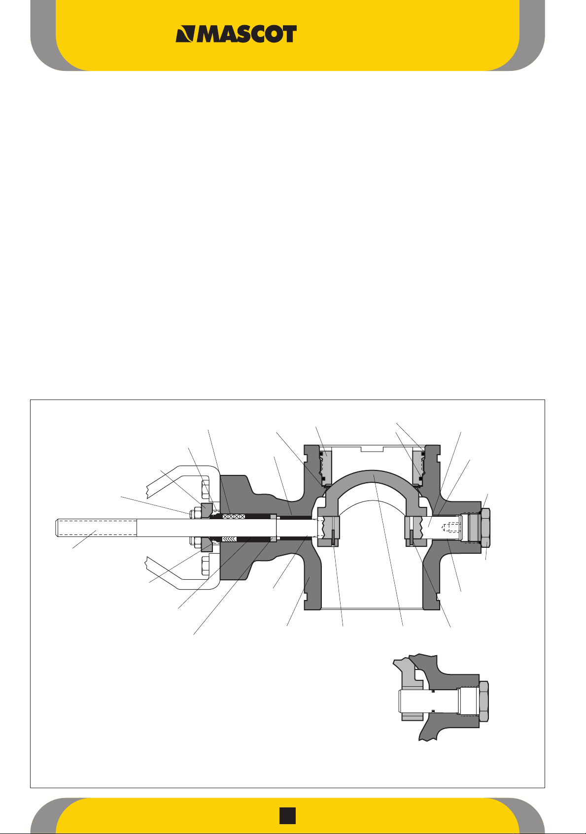
MASCOT VFlo Guide

CAUTION :
1. Use pressure relief valves for high pressure
piping.
2. Use explosion proof valves/accessories for
dangerous media piping.
3. Use fire safe valves for piping where chances of
fire by external means.
4. Use seismic proof valves where chances of
earthquake are frequent.
5. Check whether locaon of the valve mounng is
of the same service/applicaon as specified on
the marking plate.
Installation, Operation,
Maintenance Instructions
VFlo
Control Valves

VFlo Control Valves
2
GENERAL INFORMATION
The instructions presented below are for helping in un-packing,
installing and performing maintenance as and when needed on
Mascot VFlo ball valves. The manual should be thoroughly
reviewed by Product users and maintenance personnel before
performing any operation on the valve. Separate maintenance
instructions cover additional features (such as actuators, special
accessories, fail-safe systems, etc.).
For information on Mascot positioners, refer to the appropriate
Mascot Installation, Operation and Maintenance instructions.
Please follow the procedures laid down to avoid possible injury
to personnel or damage to valve parts. Any modification in this
product, or using non-factory or inferior parts, employing
maintenance procedures other than prescribed can affect
performance adversely; moreover, it can be dangerous to
personnel and equipment, and also void existing warranties.
WARNING : It is mandatory to follow standard industry safety
practices. Personal protective and lifting devices must be used
as specified.
Note : The onus of choosing the proper fastener material lies on
the customer. The supplier cannot know what the valve service
conditions or environment might exist. The standard body bolting
material for Mascot's is B7/2H. For applications above 800° F
and with stainless steel or alloy body valves B8 (stainless steel) is
optional. It is up to the customer therefore to consider the
material's resistance to general corrosion and stress corrosion
cracking. Every mechanical equipment needs periodic inspection
and maintenance. The details on fastener materials can be
obtained from your local Mascot representative or factory.
Unpacking
First step is to check packing list against the materials
received during the unpacking of the valve. Each shipping
container has lists describing the valve and accessories.
For lifting the valve from the shipping container, lifting straps
need to be positioned to avoid damage to tubing and
mounted accessories. Where valves are provided with a lifting
ring, please use the same for lifting. Valves up through 8-inch
may be lifted by the actuator lifting ring. Larger valves can be
lifted using lifting straps or hook through the yoke legs and
outer end of the body.
WARNING : During lifting of a valve with lifting straps
through the yoke legs, one must have in mind that the
center of gravity may be above the lifting point and
support must be given to prevent the valve from rotating.
Serious injury to personnel or damage to nearby
equipment can take place if proper attention is not paid to
this factor.
On observation of damage in transit, shipper should be
contacted immediately.
The Mascot representative is always at your service whenever
needed.
Quick-Check
Before beginning, check the control valve as per the steps
mentioned below:
By making the appropriate instrument signal change, verify
for full stroke. The position indicator plate is mounted on the
actuator transfer case for observation. Position of the
indicator plate should change in a smooth, rotary fashion.
CAUTION : The full torque load of the actuator cannot be
taken by the VFlo valve shaft. The shaft could twist and/or
shear if the ball were to seize and full torque continued.
There should be no leaks in the air connections. Any leaky
lines should be repaired by tightening or replacement.
Tighten of the packing nuts is to be done to slightly over
finger-tight and evenly.
CAUTION : Over tightening of packing nuts can cause
excessive packing wear and high shaft friction and shaft
rotation will be adversely affacted. Every short time valve
has been in operation, check the packing nuts to ensure
they are torqued properly. Do correction if necessary. Any
leaking in the packing box should be corrected by
tightening the packing nuts. The tightening should be only
enough to stop leakage.
In case of air failure, for observing the valve failure mode,
position the valve to mid-stroke and shut off the air supply to
the actuator or disconnect the instrument signal to the
positioner. The actuator indicator plate should move to either
fail/open or closed position. If not, the "Reversing the
Actuator Action" section in the actuator maintenance
instructions needs to be referred.
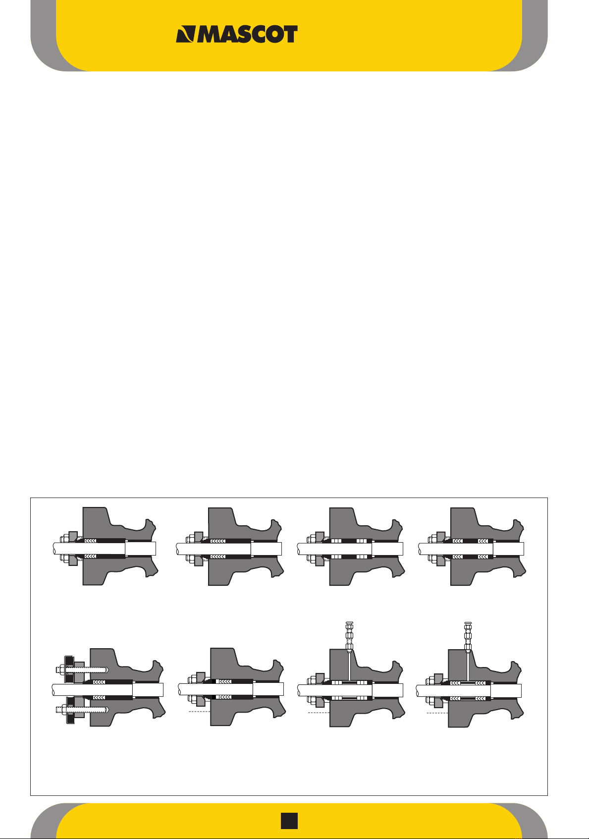
*Torque values are recommended for low and intermediate
strength bolting per ANSI B16.5 5.3.2. Higher torques may be
used with high strength bolting (ANSI B16.5 5.3.1). For all
cases the user must verify the selected bolting's ability to seat
the joint under expected operating condition. Higher strength
bolting and torque values are needed for long thrubolted
joints than shorter flanged bolting - depending on operating
conditions. **Lengths are based on ANSI B16.5 stud bolts and
raised face ends.
2.
3.
4.
1.
2.
3.
4.
1.
Table 1 : Flange Bolting Specificatiions
Valve ANSI Bolt** Torque* (ft. Lbs.)
Size Class Length Low Intermediate
(Inches) Rating (Inches) Strength Strength
150 2.5 23 61
1 300 3.0 46 122
600 3.5 46 122
150 2.75 23 61
11/2 300 3.5 82 218
600 4.25 82 218
150 3.25 46 122
2 300 3.5 46 122
600 4.25 46 122
150 3.5 46 122
3 300 4.25 82 218
600 5.0 82 218
150 3.5 46 122
4 300 4.5 82 218
600 5.75 132 353
150 4.0 82 218
6 300 5.5 132 353
600 6.75 199 531
150 4.25 82 218
8 300 6.25 199 531
600 7.5 296 789
150 4.5 132 353
10 300 6.25 199 531
600 8.5 420 1119
150 4.75 132 353
12 300 6.75 296 789
600 8.75 420 1119

VFlo Control Valves
3
PREVENTIVE MAINTENANCE
Twice yearly, operation should be checked for trouble free
performance. For the preventive maintenance, follow the steps
that are presented below:
These steps can be very well performed while the valve is in line
and, in some cases, without interrupting service. Refer to the
"Disassembly" and "Reassembly" section if an internal problem is
suspected with the valve.
Tighten flange bolting if signs of gasket leakage through the
body and line flanges are observed (See Table I for
specifications.)
Observe whether any corrosive fumes or process drippings
are damaging the valve.
Valve should be cleaned and areas of severe oxidation
painted.
Packing nuts should be tightened as necessary to prevent
Gland leakage.
CAUTION : Over tightening of packing can cause
excessive packing wear and high shaft friction, which may
retard shaft rotation.
Where the valve is supplied with a lubricator, lubricant supply
and level needs attention. Ensure proper supply and level of
the lubricant.
Where possible, stroke valve and observe for smooth, full-
stroke operation by looking at the position indicator plate
mounted on the transfer case. An internal valve problem is
indicated by unsteady movement of the plate.
In case of a positioner being present, its calibration needs to
be checked by observing the actuator position indicator plate
and gauges. The positioner needs calibration to the correct
range.
In case an actuator is attached, the appropriate maintenance
instructions for preventive maintenance need to be referred.
Where possible, remove the air supply to observe the
actuator stroke plate for correct fail-safe action.
Ensure fastening of all valve accessories, brackets and
bolting.
The exposed portion of the valve shaft must be free from dirt
or foreign material.
I case an air filter is present, the cartridge needs to be
checked and if necessary, replacement needs to be done.
Removing Valve From Line
To remove the valve from the line, in cases where an internal
problem is suspected proceed as mentioned below:
WARNING : Line must be depressurized to atmospheric pres-sure.
All process fluids should be drained. If caustic or hazardous materials
are present, decontaminate the valve. This is very important as it will
prevent any possible injury.
1.
2.
3.
4.
5.
6.
7.
8.
9.
10.
11.
Figure 1: 3", 12" and 16" VFlo Body Assembly with Rotating Post Design
Note : Item numbers correspond to bill of material of Valve. Please refer to it for specific part numbers.
StationaryPostDesign
Packing
(Item No. 88)
PackingStud
(Item No. 109)
Gland Flange
(Item No. 80)
Packing Nut
(ItemNo. 117)
Shaft
(ItemNo. 51)
RetainerRetainerO-rings
(ItemNo.30)(ItemNo.59)
(ItemNo.56)
Seals*
ShaftBearing
(ItemNo.83)
PostBearing
(ItemNo.84)
ShaftO-ring
(ItemNo.62)
(optional)
O-ring
(Item No.61)
Post
(ItemNo.123)
Post O-ring
(Item No. 64)
(optional)
Plug
(Item No. 122)
BodyShaft PinBall
(ItemNo. 1)(ItemNo.52)(ItemNo.50)
Post Pin
(Item No. 121)
Packing Follower
(ItemNo. 87)
PackingSpacer
(Item No. 93)
ThrustBearing
(Item No. 53)
(*See Figure 4 for seal configurations and item numbers.)

VFlo Control Valves
4
Support the valve with a hoist or some means.
Line bolting should be removed. Do not push or pull on the
valve or actuator to pry line flanges apart.
Valve needs to be slided from the line, carefully. Do not twist
the valve or it will cause damage to the gasket surfaces.
Slowly relieve air pressure from the actuator on complete
removal of valve from the line.
Removing Actuator From Body
The design of the 3 to 12-inch VFlo valves permits disassembly
without removing the Mascot actuator. However, it is advisable
to remove the actuator. Follow the proper actuator installation,
operation, maintenance instructions, and proceed as follows:
Before disconnecting it from the body assembly, support the
actuator assembly.
The spring compression is to be released by loosening the
actuator adjusting screw.
Remove the actuator transfer case cover bolts, carefully pry or
slide the cover plate from the transfer case, then loosen the
linkage bolt - On Mascot actuators.
The bolts connecting the yoke to the body subassembly need
to be removed.
The entire actuator assembly should be slided off the shaft. To
loosen it from the shaft splines, it may be required to wedge
the splined lever arm apart.
DISASSEMBLY AND REASSEMBLY
Disassembling the Body
Although not necessary, it is advisable to remove the actuator
from the body assembly to disassemble 3 to 12-inch bodies. It is
necessary to loosen the valve shaft (On valves) from the actuator
prior to body disassem-bly. Figures 1, 2 and 5 should be
referred to and below mentioned procedure must be followed :
Seal retainer and seals removal
Screw-in style - Loosening the retainer by turning it
counterclockwise and removing it from the body. (A special
cross-wrench tool is available with the factory and can be
ordered. Refer Table IV.) Remove the metal seals. The soft seal
needs to be removed, if applicable.
Lock-ring style - certain valve designs have a retaining ring
held in with set screws. For removing it, the set screws in the
lock ring need removal, then the re-taining ring is to be
removed, lock ring and seal retainer finally. The retaining ring
can be forced out using a flat-headed screwdriver and pliers -
if the lock ring set screws do not loosen. Remove the seals.
By removing both packing nuts, remove the gland flange.
Removing the studs is not necessary.
On rotating post designs, both the shaft and post pins need
to be driven into the center of the shaft and posted until the
outward end of the pin clears the ball. Care should be
exercised not to damage the post or shaft. Pins must be then
punched out of the shaft and posted when they are removed
from the valve. Remove the shaft plug, O-ring and finally the
rotating post. For removing the post, insert a bolt in the jack
screw hole, tapped in the post.
On stationary post designs, drive the shaft pin into the
center of the shaft until the outward end of the pin clears the
ball splines. Care should be taken, not to damage the shaft.
After the shaft is removed, the pin can then be punched out
of the shaft. The anti-rotation clamp must be removed. The
post and the post O-rings should be removed.
From 3 through 12-inch designs, for removal, the shaft needs
to be pulled through the outboard end of the body. On 1
through 2-inch designs, removal of the shaft is by pulling it
out through the inboard end of the body
CAUTION : Care must be taken during disassembly so
that the splined end of valve shaft does not get damaged.
1.
2.
3.
4.
1.
2.
3.
4.
5.
1.
2.
3.
4.
Packing
(Item No. 88)
Packing Stud
(Item No.109)
Gland Flange
(ItemNo.80)
Packing Nut
(ItemNo.117)
Shaft
(ItemNo.51)
Packing Follower
(ItemNo.87)
Packing Spacer
(ItemNo.93)
Post
(ItemNo.123)
PostO-ring
(ItemNo.64)
(optional)
Inboard End
Shaft Bearing
(ItemNo.83)Retainer O-rings
(ItemNo.59)
(ItemNo.56)
Retainer
(ItemNo.30)
Plug
(Item
No. 122)
O-ring
(ItemNo.61)
PinBallPost Bearing
(ItemNo.52)(ItemNo. 50)(Item No. 84)
Thrust Bearing
(Item No. 53)
Body
(Item No. 1)
Seals*
Figure 2: 1" & 2" VFlo Body Assembly
(*See Figure 4 for seal configurations and item numbers.)
Note : Item numbers correspond to bill of material of Valve. Please refer to it for specific part numbers.

VFlo Control Valves
5
Rotate the ball inside the body in a way so that the non-
splined end of the ball is toward the back port of the valve.
Remove the ball straight out of the body. If needed, on
stationary post designs remove the post bear-ing from the ball
by pushing it out with a press.
CAUTION : The sealing surface of the ball should not be
galled or scratched when re-moving it from body. Scratches
lead to excessive leakage and wearing of the seal.
Employing a bronze dowel with the appropriate diameter,
push the packing and bearings out of the body. The packing
must be pushed out of the body from the center of the valve.
(Refer Table IV for optional shaft/post bearing tool.)
Reassembling the Body
For the reassembling of the body subassembly, refer to Figures 1
or 2, 3, 4, and 5 and proceed as mentioned below :
All parts must be cleaned and all O-rings and soft seals must
be replaced.
The ball sealing surface must be smooth and free of scratches
and scoring.
CAUTION : Keep the seal surfaces clean and free of
damage. Damaged or dirty surfaces cause excessive seat
wear and high torque re-quirements.Prompt replacement of
damaged balls should be done.
The shaft and post are to be inspected for galled surfaces or
scratches. To achieve optimum performance, VFlo shafts and
posts are given a very smooth finish. Replace the shaft or
contact the factory representative if damage exists.
NOTE : Replacing the ball does not require replacing the shaft as
ball and shaft are interchangeable.
We recommended the use of a press to install new bear-ings
in the body and/or ball. (If needed, an optional post/
bear-ing tool is available from the factory. Refer Table IV.) The
ends of the body bear-ings should be flush with the inside of
the body - an indication of correct installation.
The ball is to be position in the body by lowering it, splined
hole first, into the back of the body. Rotate the ball surface
toward the front of the body so that the splined hole is
towards the packing box
CAUTION : Whilst, Replacing it in body be extremely
careful not to scratch or gall the sealing surface of the ball.
Scratches may cause excessive leakage and wearing of
seal
For 3 through 12-inch designs, the shaft is to be inserted
through the outboard end of the body and through the
splined inch designs, insert the shaft through the inboard end
of body and through the packing box into the splined hole of
the ball. (For 1 -inch body designs, before installing the shaft,
the thrust bearing, packing spacer, packing, and packing
follower must be inserted.)
The positioning of the shaft is to be such that the pin hole in
the shaft and ball are in alignment. (Certain shafts have a
half circle mark and line on the end. Align the line mark with
the pin and the half circle symbol with the ball.) The shaft pin
needs to be installed and driven firmly into place so that half
in the shaft and half is in the ball.
On rotating post designs, the post is to be inserted through
the outboard end of the body and into the hole of the ball.
(For 1 through 2-inch valves sizes, before installing post,
insert thrust bearing.) The post must be positioned so that the
pin hole in the post and ball are aligned. (For 6 through 12-
inch valve sizes, make certain that the ball pin hole is aligned
with the smallest diameter pin hole in the post. Some posts
have a half circle mark on the end. This half circle mark
needs to be aligned with the ball.) The post pin is to be
installed and driven firmly into place so that half is in the post
and half is in the ball. To torque the plug, refer Table Il.
5.
6.
1.
2.
3.
4.
5.
6.
7.
8.
Figure 3 : VFlo Packing Configurations
Standard
Single "V"
Standard
Twin Square
Twin "V"
Twin Square
with Lubricator
Twin "V"
with Lubricator
SafeGuard / SureGuard
Fire-safe Option
SafeGuard Live-loading
SureGuard
(packing studs
rotated 45 degrees) (live-loading omitted)

6
On stationary post designs, make sure that the lubrication of
the post and post threads is proper and done with a high
tem-perature bearing grease (or as required by the
application) before installation. The post O-ring needs to be
replaced and then reinstall the post. To torque the post, refer
Table Il. The anti-rotation clamp kit should be installed.
Over the splined end of the shaft and into the body, slide the
thrust bearing, packing spacer, Packing, and packing
follower. Most packing configurations are presented in Figure
3. (1-inch designs refer to Step 6.)
NOTE : New packing is to be used whenever rebuilding the
packing box.
CAUTION : The sealing on V-ring packing takes place at
the feather edge, so it is necessary to avoid damage to
that edge.
The gland flange is and packing nuts are to be reinstalled
and left loose.
CAUTION : Over tightening the packing can cause
excessive packing wear and shaft friction, which may
impede shaft rotation.
The valve needs to be placed on a flat surface with the
threaded (retainer) port facing up and the shaft is to be pulled
toward the actuator until it is fully against the thrust bearing.
For 3 through 12-inch designs, the ball surface must facing
up and position the ball as close as possible in the center of
the body's inside diameter. (The pinned connection between
the ball and shaft is not a tight connection; the design
includes a consid-erable amount of axial play between the
ball and shaft.)
For 1 through 2-inch designs, make sure the ball surface is
facing up and pull on the shaft until the post is fully against
the thrust bearing. (The ball does not self center. There will be
no axial play between the ball and shaft.)
Replace the soft and/or metal seal rings, as applica-ble to the
application. (Refer to Figure 4.)
In case of soft seal applications, insert the soft seal ring,
followed by the two metal seal rings into the body.
In case of metal seal applications, insert the two metal seal
rings into the body. (There is only one seal ring for 1"
designs.)
For screwed-in retainer designs, replace the O-rings in the
retainer (except on high temperature valves, which do not use
O-rings). Figure 1 or 2 should be referred. The retainer
threads and rings are to be lubricated and reinstall the
retainer in the front of the body. Torque the seal retainer
according to Table III.
For some 10 and 12-inch valves where the retainer is held in
place with set screws, reinsert the lock ring into the body. The
words "Ball Side" facing toward the ball. The lock ring has
"Ball Side" and "Port Side" marked on it. Insert the retaining
ring into the inner groove of the body. Make sure it is fully
seated. The lock ring set screws need to be evenly tightened
to a torque of 225 inch-pounds.
Once the seal retainer is in tight, the packing nuts need to be
tightened just over finger-tight. Packing nuts should be
tightened sufficiently to prevent stem leakage.
CAUTION : Over tightening of packing causes excessive
packing wear and high shaft friction, which may retard
shaft rotation.
Remounting the Actuator
Prior to initiation of the mounting of a Mascot actuator on the
valve body, verify that the ball rotation matches the actuator
rotation and complies with the air failure requirements. Method
for mounting the actuator is presented below :
9.
10.
11.
12.
13.
14.
15.
16.
Valve Stationery Rotating
Size Designs Designs
(Inches) Post Shaft Plug
1, 11/2,N/A 50
2 175 85
3, 4 300 150
6, 8 500 250
10, 12 600 300
Table II : Post/Shaft Plug Torques (Ft.-Lbs)
Valve Torque Valves Torque
Size Value Size Value
(Inches) (ft.-Lbs.) (Inches) (ft.-Lbs)
1, 11/2, 2 150-175 8, 10 650-700
3 250-300 12 900-950
4, 6 550-600 - -
Table III : Screwed-in-Retaineer Torques
Figure 4: Seat Configurations
* Two metal seals required for shaft upstream
Soft lateM*lauD
Retainer/
Flow Ring
(Item No. 30)
Ball
(Item No. 50)
Ball
(Item No. 50)
Body
(Item No. 1)
Body
(Item No. 1)
Metal Seal
(Item No. 20)
Retainer
(Item No. 30)
Soft Seal
(Item No. 21)
Soft Seal
(Item No. 21)
Ball
(Item No. 50)
Retainer
(Item No. 30)
Body
(Item No. 1)
Metal Seal
(Item No. 20)
Ball
Metal Seal
(Item No. 20)
Body
(Item No. 1)
Retainer
(Item No. 30)
Ball
(Item No. 50)
Bi-directional Metal
VFlo Control Valves

VFlo Control Valves
7
Entire actuator assembly is to be slided onto the shaft.
The yoke needs to be bolted to the valve body.
The actuator lever arm should be positioned on the shaft so
the actuator stem is centered in the transfer case.
The linkage bolt should be firmly tightened. Bolt the transfer
case cover plate into place.
Alignment of the stroke indicator plate to be done on the end
of spline lever so that it accurately indicates position of ball.
CAUTION : Without the cover plate installed; never apply
air to the actuator otherwise, the unsupported shaft is likely
to sustain damage.
The valve is to be installed in the line as outlined in the
"Installation" section.
Table IV: Optional VFlo Tools
Valve Retainer Shaft/Post
Size Tool Bearing Tool
1 87377 76891
11/2 87530 76509
2 76112 76509
3 62295 75970
4 62294 75970
6 62296 81978 / 81974
8 62336 81978 / 81974
10 81775 76550 / 76551
12 81034 76550 / 76551
1.
2.
3.
4.
5.
6.
Gland Flange Stud (Item No. 109)
Gland Flange Nut
(Item No. 117)
Half Ring
(Item No. 11)
Body
(Item No. 1)
Shaft (Item No. 51)
End Plug (Item No. 122)
End Plug O-ring (Item No. 61)
Post (Item No. 123)
Half Ring
(Item No. 11)
End Flange
(Item No. 10)
Post Pin
(Item No. 121)
Post Bearing
(Item No. 84)
Shaft Pin
(Item No. 52)
Ball
(Item No. 50)
Shaft Bearing
(Item No. 83)
Yoke Bolt (Item No. 107)
Packing
(Item No. 88)
End Flange
(Item No. 10)
Seal Rings
(Item No. 20)
Soft Seal Insert (Item No. 21)
Retainer O-ring (Item No. 56)
Retainer O-ring (Item No. 59)
Seal Retainer (Item No. 30)
Packing Spacer (Item No. 93)
Thrust Bearing (Item No. 53)
Packing Follower (Item No. 87)
Gland Flange (Item No. 80)
Figure 5: Exploded Body Subassembly, 3", 12" and 16" VFlo
Note : Item numbers correspond to bill of material of Valve. Please refer to it for specific part numbers.
Failure Probable Cause Corrective Action
Valve moves to failure position, excessive air 1. Failure of actuator O-ring 1.Replace actuator stem O-ring
bleeding from transfer case 2. Failure of sliding seal assembly 2.Repair or replace stem adapter / linkage assembly
Jerky shaft rotation 1. Overtightened packing 1.Retighten packing box nuts to slightly over finger-tight
2. Improper adjustment of lever arm on shaft causing arm 2. Readjust lever arm (see step 1 in the
to contact transfer case thus failing to convert torque. “Remounting Actuator” section)
3. Cylinder wall not lubricated 3.Lubricate cylinder wall with silicone lubricant
4. Worn piston O-ring allowing piston to gall on cylinder wall 4. Replace O-ring; if galling has occurred replace all damaged parts
5. Worn actuator stem O-ring causing ctuator stem to gall on stem collar 5. Replace O-ring; if actuator stem is galled replace it
6. Worn (or damaged) shaft bearings, shaft bearings or packing followers 6. Disassemble and inspect parts; replace any worn or damaged parts
Excessive leakage through seal 1. Improper adjustment of external stroke stops 1. See “Adjusting External Stroke Stops” section
2. Worn or damaged seat 2. Replace seat
3. Damaged ball seating surface 3. Replace disc and shaft
4. Improper handwheel adjustment acting as limitstop 4. Adjust handwheel until disc seats properly
5. Ball not centered in body I.D. 5. Center ball; replace damaged seals.
Leakage through line flanges 1. Dirty line gasket surfaces 1. Clean gasket surfaces and reinstall valve
2. Improper torque on line flanges 2. Tighten line flanges evenly and completely (see Table 1 for proper torque)
3. Flange or pipe misalignment 3.Realign flanged ends with piping.
4. Warn Gaskets 4.Replace Gaskets
Leakage through packing box 1. Loose packing box nuts 1. Tighten packing box nuts to slightly over finger-tight
2. Worn or damaged packing 2. Replace packing
3. Dirty or corroded packing 3. Clean body bore and stem, replace packing
Valve slams, won’t open, or 1. Improper valve installation 1. See step 2 in “Installation” section and
causes severe water hammer correct flow direction
Shaft rotates, ball remains open or closed 1. Broken shaft 1.Replace shaft
Actuator operates, shaft does not rotate 1. Broken internal actuator parts 1. Refer to appropriate actuator Maintenance Instructions
Troubleshooting VFlo Valve

MASCOT VALVES PVT. LTD.
166 / 167, G I D C, Naroda, Ahmedabad : 382330.India
Phone : +91 79 22821619/22823369, Fax : +91 79 22822430
Email : info@mascotvalves.com / web : www.mascotvalves.com
Table of contents
Other MASCOT Control Unit manuals
Popular Control Unit manuals by other brands

Clack Valve
Clack Valve WS1.25 Operation and instruction manual

Samson
Samson 3354 Mounting and operating instructions

AQUATROL
AQUATROL POWERFLO AQT-315 Service manual

System Sensor
System Sensor M501MAP Installation and maintenance instructions

Texas Instruments
Texas Instruments DLP NIRscan EVM user guide

CALEFFI
CALEFFI 513 Series manual