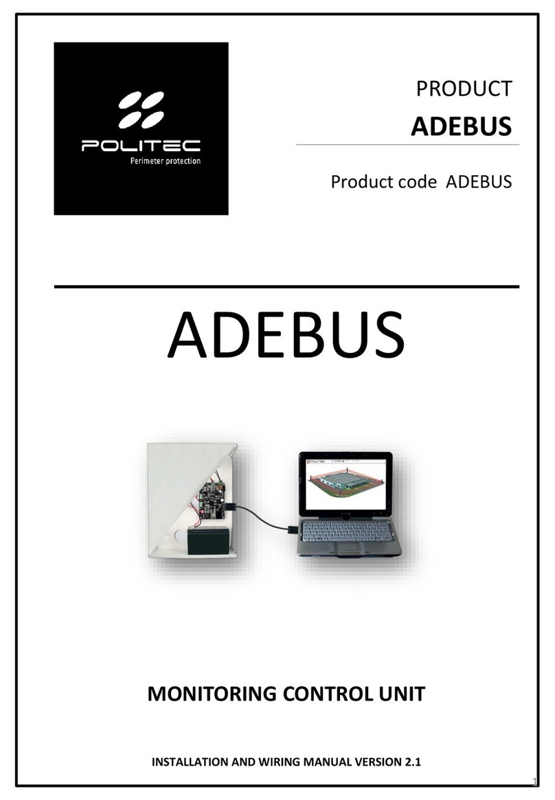
Politec ADEBUS User manual

PRODUCT
ADEBUS &
GAPID EXPLORER
ADEBUS &
GAPID EXPLORER
Product code ADEBUS & GAPID
EXPLORER
MONITORING CONTROL UNIT
INSTALLATION AND WIRING MANUAL VERSION 1.8
1

Table of contents
2
ADEBUS & GAPID EXPLORER
1.Introduction…………………………………………………………………………………………………………………………………...3
2.Product description …………………………………………………………………………………………….………………….. 3
3.General warnings……………………………………………………………………………………………………………………….…. 4
3.1 Additional warnings for devices powered by mains voltage
3.2 Installation warnings
4.List of main components ………………………………………………………………………………………………………………..5
4.1 The control unit
4.2 Gapid SR
5.Description of the boards ……………………………………………………………………………………………………………… 7
5.1 ALPO1B - Power supply board
5.2 ADEBUS G - Adebus motherboard
5.3 ADEBUS ESP - Expansion of 16 relay outputs for Adebus
5.4 ADEBUS INTERFACE
6.Preparation for installation …………………………………....…………………………………………..………………………...10
6.1 Preparing the components before installation
6.2 It is advisable to carry out
7.Sensor mounting …………………………………………………………….……………………………………………………………...11
8.Relay output connections.…………………………………....…………………………………………………………………………13
9.Gapid SR sensor …………………………….…………………………………………………………………………..……….......14
10.Installation method ………………………………………………....……………………………………………………………….….15
11.Connection of sensors to the control unit ................................................................……………………... 17
12.First access to the Adebus G board via IP address 192.168.1.222 ……………………………………….....……..18
13.Gapid Explorer installation …………………………………………………….………………………………………………........19
14.First start-up ………………………………………………………………………………………………….……………………...........21
14.1 Main screen
14.2 Working path
14.3 Site creation
14.4 Site configuration
14.5 Single sensor configuration
14.6 Operating condition
15.Configuration and management via web. …………………………………..………….………………………….….….... 30
16.Archive ............................................................................................................................................... 31
16.1 Description of events
17.Settings………………………………………………………………………………………………………………………………………….32
17.1 Enable pop up
17.2 Reset Adebus G board
17.3 Advanced configurations - Group
17.4 Advanced configurations - Gapid SR
17.5 Advanced configurations - System configuration
17.6 Advanced configurations - Send group structure
17.7 Advanced configurations - Logout
18.Gapid SR Technical specifications……………………………………………………………………………………………..... 42
18.Adebus Gapid Technical specifications……………………………………………………………………………………..... 43
20.Product disposal.…………………………………………………………………………………………………………………..….….44
POLITEC | INSTALLATION MANUAL - VER.1.8

1.Introduction
3
ADEBUS & GAPID EXPLORER POLITEC | INSTALLATION MANUAL - VER.1.8
Congratulations on having purchased the Politec monitoring control unit.This appliance
guarantees long-lasting and reliable operation if installed correctly.For correct and effective use,
it is necessary to read this instruction manual carefully.
The sensor and the monitoring control unit have been designed to detect intrusions
and activate the alarm; it is not a device that prevents intrusion.Politec is not
responsible for damage, injury or loss caused by accidents, theft, force majeure
(including momentary lightning-induced overcurrent), abuse, improper or incorrect
use, faulty installation or inadequate maintenance.
2. Product description
The Adebus & Gapid Explorer is a monitoring control unit for the management of up to 128
sensors divided arbitrarily into 2 branches (expandable) using both the serial ports Com0 and
Com1.Adebus Gapid manages, supervises and configures every single Gapid SR (or groups)
combined with Adebus hardware boards, set up with the appropriate firmware, reachable
through a TCP/IP connection.
This system is ideal for sensor management for perimeter protection of large areas.
It is equipped with an internal algorithm system that allows multiple sensors to be installed on
the same site in different applications and realtime management of every single vibration.The
main features of this system are as follows:
•Detection of each alarm of the individual group or sensor.
•Ability to interact on all system parameters, to know and change the status of the sensors
(single or group);
•Each sensor, single or in group, can be configured and verified in real time: all operations can
be performed locally or remotely via WEB;
•Store and download up to 32000 events on aPC.
Warnings
Mounting, installation of the barrier and connection to the mains must be carried out
by expert and qualified personnel, in compliance with rules and regulations applicable
to electrical systems.

3.General warnings
4
ADEBUS & GAPID EXPLORER
This installation manual contains important information regarding safety for installation: it is
necessary to read all the instructions before proceeding with the installation.
Keep this manual for future use.
•If you have any questions or doubts during installation, do not carry out any operations and contact
the support service.
•Use of these products for purposes other than those specified in these instructions is prohibited.
•You must not make any change to the components of the product unless stated in the manual in
order not to void the warranty; such operations can only lead to malfunctions; Politec assumes no
liability for malfunctions or damage due to modified products.
•Depending on the specific situation of use, check for the need for additional devices: detectors or
signalling devices.
•During installation, mounting and use of the product, make sure no foreign objects (solids, metals
or liquids) are able to penetrate inside the open devices.
•Manufacturer's liability:Politec assumes no liability for failures resulting from incorrect installation;
lack of maintenance, incorrect assembly or use.
•Politec is also not liable for incorrect or incomplete operation of the product or failure to detect
intrusion.
•Warranty (summary of conditions):Politec guarantees its products for a period of 2 years from the
production date.The warranty is applied to those purchasing directly from Politec; there is no
warranty for the end user who, in the event of breakdowns or faults, must contact the installer or
dealer.
•The warranty excludes aesthetic parts as well as parts subject to normal wear and parts subject to
normal consumption such as batteries and accumulators.
3.1 Additional warnings for devices powered by mains voltage
This manual is intended only for technical personnel qualified to install such devices.
•Assessing the hazards that may occur during installation and use of the system, in order to achieve
complete safety, it is necessary that installation takes place in full compliance with applicable laws,
methods, rules and regulations.
•Before accessing the internal terminals of the product, it is necessary to disconnect all the power
circuits.
•If automatic circuit breakers or fuses trip, before resetting them it is necessary to identify the fault
and repair it.
3.2 Installation warnings
•Check that all the material to be used is in excellent condition and suitable for use.
•Before proceeding with the installation, check the environmental class of the products in the
"technical specifications" chapter.
•Check, by comparing with the values shown in the paragraph "technical specifications".
•Do not place the system components close to heat sources as they could be damaged.
•Each product has its own operating principle: check the instructions for choosing the right position
in the respective instruction manual.
POLITEC | INSTALLATION MANUAL - VER.1.8

N
o.
COMPONENT CODE
DESCRIPTION
1
ADEBUS G
Adebus motherboard
2
ADEBUS ESP
Expansion of 16 relay
outputs
3
INTERFACE BOARD
4
TRASF
LAR22S
18/24 Vac transformer
5
ALPO1B
Power supply board
6
BATTERY (not
included)
17 Ah Battery
compartment
7
TAMPER
5
ADEBUS & GAPID EXPLORER
4.1 The control unit
The box contains the following components and accessories.
When opening the package, check that everything has been included.
POLITEC | INSTALLATION MANUAL - VER.1.8
4
6
1
3
7
4.Main components list
2
5

No
.
COMPONENT
1
Screw 3x7
2
Gapid SR cover
3
Serial CS board
4
Screw 3x20
5
Gapid SR container
6
Fixing plate
7
Cable
glands
6
ADEBUS & GAPID EXPLORER
4.2 Gapid SR
The box contains the following components and accessories.
When opening the package, check that everything has been included.
POLITEC | INSTALLATION MANUAL - VER.1.8
1
5
6
2 3
4
7

No
.
COMPONENT
1
18 Vac input
2
24 Vac input
3
24 Vac output
4
0
-13.8 Vdc outputs
5
Battery output
6
10 A fuse (24 Vac)
7
3 A fuse (12 Vac)
8
3 A fuse (battery)
5.Board Description
7
ADEBUS & GAPID EXPLORER
5.1 ALPO1B - Power supply board.
POLITEC | INSTALLATION MANUAL - VER.1.8
1
5
6
2
3
4
7
8

No
.
COMPONENT
1
Serial input line COM1
2
Serial input line COM2
3
0
-12 Vdc input
4
LAN port
5
Relay outputs block
6
Inputs
7
Relay expansion connection
8
ADEBUS & GAPID EXPLORER
5.2 ADEBUS G - Adebus motherboard.
POLITEC | INSTALLATION MANUAL - VER.1.8
16 3
7
2
4
5

No.
COMPONENT
1
0
-12 Vdc input
2
Relay outputs block 1
-8
3
Output connector to next
expansion board
4
Relay outputs block 9
-16
5
Input connector from CA 230
motherboard
6
Input connector from previous
expansion board
9
ADEBUS & GAPID EXPLORER
5.3 ADEBUS ESP - Expansion of 16 relay outputs for Adebus.
POLITEC | INSTALLATION MANUAL - VER.1.8
1
6
3
2
4
5
No
.
COMPONENT
1
Serial input line COM1
2
Serial input line COM2
3
Adebus connection
1
2
3
5.4 ADEBUS INTERFACE

6.Preparation for installation
10
ADEBUS & GAPID EXPLORER
6.1 Preparing the components before installation
Since the communication between the sensors and the monitoring unit takes place by wire, it is
advisable to firstly check that all the parts of the unit and sensors and their possible accessories are
present before beginning the installation.
6.2 It is advisable to carry out:
•The installation of the control panel application on a computer
•The installation of the sensors on the perimeters to be protected;
•checking sensor operation using software
•the permanent fixing of each sensor;
•the preparation and carrying out of electrical connections.
In order to avoid errors, operating and installation problems, it is advisable to proceed as follows:
a) Place all the products with the package open on a table;
b) Test the functioning of the sensors;
c) Arrange (without fixing) the sensors in the planned points;
d) Check that each sensor responds from the application;
e) Permanently fix the sensors.
Before proceeding with the installation, it is necessary to check the integrity of the product, the
adequacy of the model chosen and the suitability of the environment intended for installation:
• Check that all conditions of use fall within the "limits of use" and in the "Technical specifications of
the product".
• Check that the environment chosen for the installation is compatible with the total footprint of the
product.
• Check that the surface chosen for the installation of the product is solid so as to ensure stable fixing
and that it is adequately protected from possible impacts or atmospheric agents.
POLITEC | INSTALLATION MANUAL - VER.1.8

7.Sensor mounting
11
ADEBUS & GAPID EXPLORER
Placement and installation height
This type of sensor has the optimal sensitivity of a diameter of 5 metres on all types of fences, metal
structures and gates.If the fence is supported by poles about 5 metres apart, position the sensor in the
centre of this distance, so as to place one in each "sector".
However, it is necessary to take into consideration the type of material of the fence since, depending
on whether it is loose mesh, electro-welded or with panels, the material will transmit a different
sensitivity.
POLITEC | INSTALLATION MANUAL - VER.1.8
Position the Gapid in the centre of the panel
or the mesh and screw it to the fixing plate
positioned on the other side.Tighten the
screws firmly to prevent the device from
moving.
Fasten the cable with cable ties to the fence or support
on which you have mounted the Gapid SR and wire the
sensors.
After calibration and programming, close the device
making sure that the gasket is well positioned inside
the special compartment and that the protective cover
closes well.
The Gapid SR can be connected to the net and to the
Adebus control unit only with the cable supplied which
is RS485.
The cable must be inserted in the two slots below: one
for input and one for output.
After that, wire the sensors.
The last sensor in line will only have the input cable.At
this point, unscrew the 4 screws of the cable gland
plate and replace the perforated gasket with the
supplied cap
WARNING:
Product warranty is invalid if there is any hole in the product profile or any component

8.Start-up
12
ADEBUS & GAPID EXPLORER
The ADEBUS system manages up to 256 Gapid SR divided into 2 branches (maximum length 750m
each) using both the serial ports Com1 and Com2 (for Com1 the ADEBUS S2 accessory is required),
On the other hand, using a single serial port it is mandatory to create a single branch of the RS485 bus,
without making further branches.In this case, however, 128 sensors can be used on the same branch.
The system is accessible via dedicated software and via the WEB
POLITEC | INSTALLATION MANUAL - VER.1.8
MAX 750m MAX 750m

9.Relay output connections
13
ADEBUS & GAPID EXPLORER
The condition of use of the contacts indicated on the board (NC, NO) refers to the relay in the rest
condition, if the relays are energised the operating condition is reversed.
N.B.:The connections of the Relay outputs are divided into 4 groups for each expansion board, and
the common ones are as follows:
C1-4 = common first 4 relays
C5-8 = common second 4 relays
C9-12 = common third 4 relays
C13-16 = common fourth 4 relays
POLITEC | INSTALLATION MANUAL - VER.1.8
C1-4
NO1
NC1
NO2
NC2
NO3
NC3
NO4
NC4
NO5
NC5
NO6
NC6
NO7
NC7
NO8
NC8
C5-8
C13-16
NC16
NO16
NC15
NO15
NC14
NO14
NC13
NO13
NC12
NO12
NC11
NO11
NC10
NO10
NC9
NO9
C9-12

10.Gapid SR sensor
14
ADEBUS & GAPID EXPLORER
Tamper
POLITEC | INSTALLATION MANUAL - VER.1.8
Signalling buzzer
(activated via software)
Ci
+
A
B
-
Co
+
A
B
-
Input Connector:
Connection to the previous
Gapid or the Adebus control
unit
Output Connector:Connection
to the next Gapid
Sensitivity adjustment trimmer:It is
generally used to check sensitivity in
the field.This sensitivity will be
overwritten via software.
The accelerometer sensor has a detection around 5m for a maximum of 7m, it can vary depending on
the fencing on which it is mounted.

10.Installation Method
15
ADEBUS & GAPID EXPLORER POLITEC | INSTALLATION MANUAL - VER.1.8
Mount the sensors equidistant from each other so that the vibrations they will receive are the same
for all sensors.Begin mounting the first sensors of each serial branch starting from the beginning of the
fencing.
N.B.:For correct operation, all sensors placed on the same side of a continuous fence must be
connected to the same branch as in the drawing below.
P
V
Panel 1 Panel 2

16
ADEBUS & GAPID EXPLORER POLITEC | INSTALLATION MANUAL - VER.1.8
Operating principles and applications
The system is designed for detection in the event of a breach, trespassing and cutting.
In the case of mounting on masonry, the system only detects an attempt at breaching.
In the case of mounting on netting, cut detection occurs when a potential intruder cuts the
netting/mesh and tries to pass through it.
In the case of non-welded netting/mesh mounting, it is necessary to use a panel sensor to have an
efficient level of protection against cutting.
The system works properly only if the fencing is stable and uniform.
Standard applications
-Light wire mesh panels: typical mounting in the centre of alternate panels, i.e. one yes, one no.If
vibrations are propagated considerably, it is possible the to mount one every three panels, i.e. one
yes and two no.
-Rigid wire mesh panel: typical mounting in the centre of alternate panels, i.e. one yes, one no.If
vibrations are not propagated very much, mount a sensor on each panel.
-Non-welded meshing: typical mounting near the anchoring post, mounting of a sensor on each
section for cutting detection.
-Rigid welded meshing: typical mounting in the centre of alternate sections, i.e. one yes, one no.If
vibrations are propagated considerably, it is possible to mount one every three panels, i.e. one yes
and two no.
-Anti-breach wall: depending on the structure of the wall, typically mount a sensor every 5m.
-Windows or internal applications: mount a sensor every 5m depending on the structure.

11.Connection of sensors to the control unit
17
ADEBUS & GAPID EXPLORER POLITEC | INSTALLATION MANUAL - VER.1.8
The connection of the Gapid SR sensors to the Adebus control unit must be made exclusively with the
serial cable («input and output» mode) following the diagram below:
Ci
+
A
B
-
Co
+
A
B
-
If required, make the
same connection for
COM2
Vdd
Braid Braid
R
Ci
+
A
B
-
Co
+
A
B
-
Ci
+
A
B
-
Co
+
A
B
-
BLACK
BraidBraid
WHITE
BLUE
RED
R
N.B.:Connect an R of 10k between Ci and power Positive on the first sensor of the line, do not close
the ring.
A BGnd

12.First access to the Adebus G board via IP address 192.168.1.222
18
ADEBUS & GAPID EXPLORER POLITEC | INSTALLATION MANUAL - VER.1.8
Connect the PC to the LAN connector of the ADEBUS G board with Ethernet cable.
The system is accessible via Gapid Explorer software or via the WEB.
N.B.: for the first access:
username: admin,
password: admin.
12.1 Overview via web

13.Gapid Explorer installation
19
ADEBUS & GAPID EXPLORER POLITEC | INSTALLATION MANUAL - VER.1.8
Install the supplied Gapid Explorer program using the WinXP.lnk.exe file.The program is compatible
with Windows 7 and newer versions.
13.1 Gapid Explorer
Gapid Explorer is a supervision and configuration program for Gapid SR sensors.
The software can be used in three different languages (English, Italian, French).
13.2 First access: direct PC connection - Adebus G
• Make direct connection with Static IP address.
• network connections (e.g. WINDOWS 7);
• with the left button of the mouse choose and click connection to the local network (LAN)

20
ADEBUS & GAPID EXPLORER POLITEC | INSTALLATION MANUAL - VER.1.8
With the left button of the mouse choose and click properties.Once the window is open, with the left
button of the mouse choose Internet Protocol and click Properties.
Choose, if not already selected, an IP address different from that of the ADEBUS G board (default is
192.168.1.222) for example the address 192.168.1.223 and click on Subnet mask so that the following
appears:255.255.255.0Save with OK.
Other manuals for ADEBUS
1
This manual suits for next models
1
Table of contents
Other Politec Control Unit manuals
Popular Control Unit manuals by other brands

Leroy-Somer
Leroy-Somer R 725A Connection and Adjustments

Allied Motion
Allied Motion SPECTRUM CONTROLS 1769 user manual

Simplex
Simplex MINIPLEX 4100ES Series quick start guide

PARCOL
PARCOL 1-6940 Series instruction manual

Desin Instruments
Desin Instruments DAS-8000 quick guide

Campbell
Campbell TEMP 120 product manual