
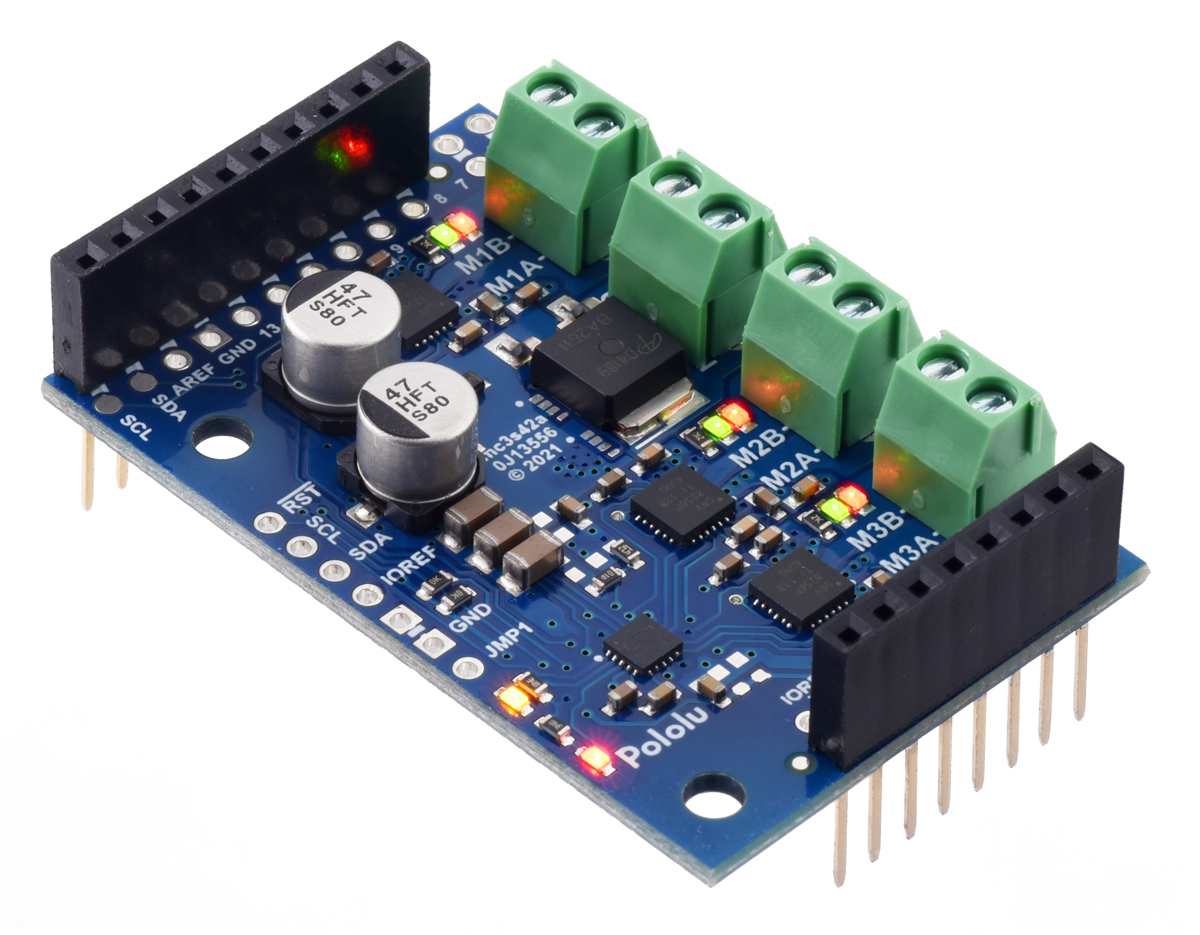
Pololu Motoron Motor
Controller User’s Guide
1. Overview . . . . . . . . . . . . . . . . . . . . . . . . . . . . . . . . . . . . . . . . . . . . . . 2
1.1. Available versions . . . . . . . . . . . . . . . . . . . . . . . . . . . . . . . . . . . . . . 4
2. Contacting Pololu . . . . . . . . . . . . . . . . . . . . . . . . . . . . . . . . . . . . . . . . . 11
3. Getting started . . . . . . . . . . . . . . . . . . . . . . . . . . . . . . . . . . . . . . . . . . 12
3.1. Choosing the power supply and motor . . . . . . . . . . . . . . . . . . . . . . . . . . 12
3.2. Connecting everything . . . . . . . . . . . . . . . . . . . . . . . . . . . . . . . . . . . 13
3.3. Enabling I²C on the Raspberry Pi . . . . . . . . . . . . . . . . . . . . . . . . . . . . . 16
3.4. Setting I²C addresses with a Raspberry Pi . . . . . . . . . . . . . . . . . . . . . . . . 17
3.5. Setting I²C addresses with an Arduino . . . . . . . . . . . . . . . . . . . . . . . . . . 18
3.6. Writing code . . . . . . . . . . . . . . . . . . . . . . . . . . . . . . . . . . . . . . . . 20
4. Motoron M3S256 pinout . . . . . . . . . . . . . . . . . . . . . . . . . . . . . . . . . . . . . 24
5. Motoron M3 256 pinout . . . . . . . . . . . . . . . . . . . . . . . . . . . . . . . . . . . . . 26
6. LED feedback . . . . . . . . . . . . . . . . . . . . . . . . . . . . . . . . . . . . . . . . . . 28
7. I²C interface . . . . . . . . . . . . . . . . . . . . . . . . . . . . . . . . . . . . . . . . . . . 30
8. Variable reference . . . . . . . . . . . . . . . . . . . . . . . . . . . . . . . . . . . . . . . . 32
9. Command reference . . . . . . . . . . . . . . . . . . . . . . . . . . . . . . . . . . . . . . . 51
10. Cyclic redundancy check (CRC) . . . . . . . . . . . . . . . . . . . . . . . . . . . . . . . . 66
11. Reset pin . . . . . . . . . . . . . . . . . . . . . . . . . . . . . . . . . . . . . . . . . . . . 67
Pololu Motoron Motor Controller User’s Guide © 2001–2022 Pololu Corporation
https://www.pololu.com/docs/0J84/all Page 1 of 67


