1
SWRU539–January 2019
Submit Documentation Feedback Copyright © 2019, Texas Instruments Incorporated
CC3235x SimpleLink™ Wi-Fi®LaunchPad™ Development Kit (LAUNCHXL-
CC3235x)
User's Guide
SWRU539–January 2019
CC3235x SimpleLink™ Wi-Fi®LaunchPad™
Development Kit (LAUNCHXL-CC3235x)
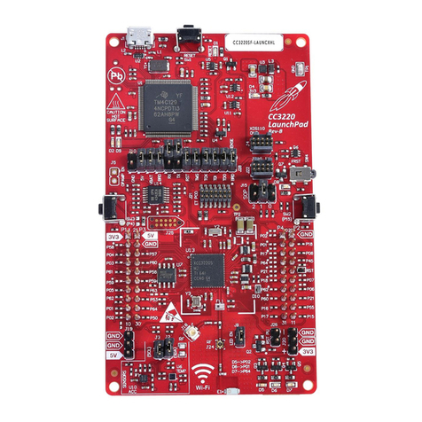
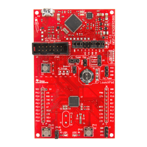
The CC3235 SimpleLink™ LaunchPad™ Development Kit (LAUNCHXL-CC3235x) is a low-cost
evaluation platform for Arm®Cortex®-M4-based MCUs. The LaunchPad (LP) design highlights the
CC3235 Dual Band (2.4 GHz and 5 GHz) wireless MCU system on a chip. The CC3235 LaunchPad™ kit
also features temperature and accelerometer sensors, programmable user buttons, RGB LED for custom
applications, and onboard emulator for debugging. The stackable headers of the LAUNCHXL-CC3235x
demonstrate how easy it is to expand the functionality of the LaunchPad™ kit. BoosterPack™ Plug-in
Modules allow for interfacing with other peripherals such as graphical displays, audio codecs, antenna
selection, environmental sensing, and more.
The CC3235S and CC3235SF devices are part of the SimpleLink™ microcontroller (MCU) ecosystem
which consist of Wi-Fi®, Bluetooth®low energy, Sub-1 GHz and host MCUs. All share a common, easy-to-
use development environment with a single core software development kit (SDK) and a rich tool set. A
one-time integration of the SimpleLink™ platform lets you add any combination of devices from the
portfolio into your design. The ultimate goal of the SimpleLink™ platform is to achieve 100% code reuse
when your design requirements change. For more information, visit www.ti.com/SimpleLink.
Contents
1 Introduction ................................................................................................................... 3
1.1 CC3235x LaunchPad™ Development Kit ....................................................................... 3
1.2 Key Features ........................................................................................................ 3
1.3 Kit Contents.......................................................................................................... 3
1.4 Regulatory Compliance ............................................................................................ 4
2 Hardware Description ....................................................................................................... 5
2.1 Block Diagram....................................................................................................... 6
2.2 Hardware Features ................................................................................................. 7
2.3 Connecting a BoosterPack™ ..................................................................................... 8
2.4 Wired Connections, Jumper Settings, Buttons, and LEDs .................................................... 9
2.5 Power ............................................................................................................... 18
2.6 Isolated Current Measurement of the CC3235 Device....................................................... 21
2.7 RF Connections ................................................................................................... 23
2.8 Assembly Drawing ................................................................................................ 25
List of Figures
1 CC3235 LaunchPad™ Board Overview.................................................................................. 5
2 CC3235 LaunchPad™ Block Diagram.................................................................................... 6
3 Pin 1 Marking on CC3235 LaunchPad™ (3v3 Tag) .................................................................... 8
4 Default Jumper Configuration for JTAG Lines........................................................................... 9
5 JTAG IN Connector........................................................................................................ 10
6 I2C Connections ............................................................................................................ 11
7 Power Jumpers J28, J23, J24, J18, J21, and J22..................................................................... 12
8 External Supply Connections and LED Enable Jumper............................................................... 13
9 SOP Jumpers (Default Setting Shown) ................................................................................. 14
10 UART Routed to USB COM Port......................................................................................... 15
11 UART Routed to 20-Pin Header Connector ............................................................................ 15
12 CC3235 BoosterPack™ Header Pin Assignments .................................................................... 17
