PolyVision CopyCam User manual

Exhibit X: Installation Guide
FCC ID: P6I-COPYCAM

Part Number 370-0112-01
©2002 PolyVision Corporation
All rights reserved
Printed in the USA
Installation Guide
Installguide_RevA_4.fm Page -1 Friday, January 18, 2002 11:05 AM

Information in this document is subject to change without notice.
Reproduction in any manner without written permission of
PolyVision Corporation is forbidden.
PolyVision Corporation reserves the right to make changes in
product design, or detail, and to discontinue any product or
material without notice.
CopyCam is a trademark of PolyVision Corporation, a Steelcase
Company.
The Bluetooth trademarks are owned by Bluetooth SIG, Inc., USA.
Installguide_RevA_4.fm Page 0 Friday, January 18, 2002 11:05 AM

1
TABLE OF CONTENTS
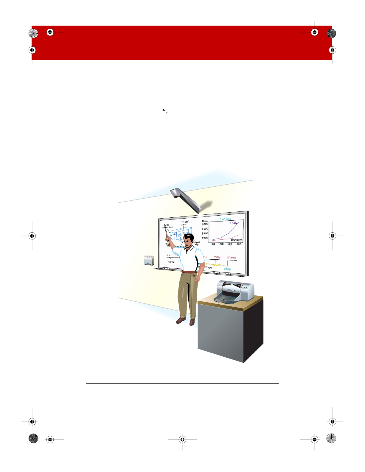
Overview . . . . . . . . . . . . . . . . . . . . . . . . . . . . . . . . . . . . . . . . . . . . . . . . . .3
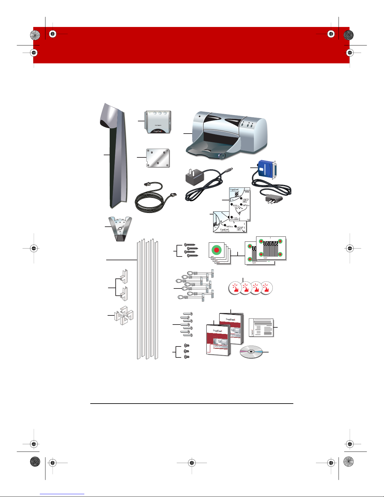
What Comes in the Box . . . . . . . . . . . . . . . . . . . . . . . . . . . . . . . . . . .4
Spatial Requirements . . . . . . . . . . . . . . . . . . . . . . . . . . . . . . . . . . . .6
Mounting the Control Pad and Camera Arm . . . . . . . . . . . . . . . . . . . . . . 7
Planning for Wiring. . . . . . . . . . . . . . . . . . . . . . . . . . . . . . . . . . . . . . .7
Mounting CopyCam Against the Wall . . . . . . . . . . . . . . . . . . . . . . . .8
Preparing to Install the Control Pad . . . . . . . . . . . . . . . . . . . . . . .8
Installing the Control Pad Mounting Plate . . . . . . . . . . . . . . . . . .8
Routing the Control Pad Cable . . . . . . . . . . . . . . . . . . . . . . . . . . 11
Locking the Control Pad in Place . . . . . . . . . . . . . . . . . . . . . . . . 12
Removing the Control Pad From its Mounting Plate . . . . . . . . . 13
Preparing to Install the Camera Arm. . . . . . . . . . . . . . . . . . . . . . 14
Installing the Camera Arm Mounting Plate. . . . . . . . . . . . . . . . . 14
Cable Routing and Connections in the Camera Arm . . . . . . . . . 17
Locking the Camera Arm in Place . . . . . . . . . . . . . . . . . . . . . . . . 18
Concealing Cables . . . . . . . . . . . . . . . . . . . . . . . . . . . . . . . . . . . .19
Routing Cables Within the Wall. . . . . . . . . . . . . . . . . . . . . . . . . . . .20
Installing and Testing the Printer . . . . . . . . . . . . . . . . . . . . . . . . . . . . . .23
About the Color Printer... . . . . . . . . . . . . . . . . . . . . . . . . . . . . . . . . .23
Installing the Printer. . . . . . . . . . . . . . . . . . . . . . . . . . . . . . . . . . . . .23
Testing the Printer . . . . . . . . . . . . . . . . . . . . . . . . . . . . . . . . . . . . . .24
Evaluating the Test Copy . . . . . . . . . . . . . . . . . . . . . . . . . . . . . . .24
Calibrating CopyCam. . . . . . . . . . . . . . . . . . . . . . . . . . . . . . . . . . . . . . . .25
When to Calibrate CopyCam . . . . . . . . . . . . . . . . . . . . . . . . . . . . . .25
How to Calibrate CopyCam . . . . . . . . . . . . . . . . . . . . . . . . . . . . . . .25
Materials. . . . . . . . . . . . . . . . . . . . . . . . . . . . . . . . . . . . . . . . . . . .25
Calibrating CopyCam . . . . . . . . . . . . . . . . . . . . . . . . . . . . . . . . . .26
Web Configuration and Testing . . . . . . . . . . . . . . . . . . . . . . . . . . . . . . .29
CopyCam Web Server Introduction . . . . . . . . . . . . . . . . . . . . . . . . .29
Configuring the CopyCam Web Server . . . . . . . . . . . . . . . . . . . . . .29
Troubleshooting . . . . . . . . . . . . . . . . . . . . . . . . . . . . . . . . . . . . . . . . . . .33
Installguide_RevA_4.fm Page 1 Friday, January 18, 2002 11:05 AM

2
Voice Status Messages . . . . . . . . . . . . . . . . . . . . . . . . . . . . . . . . . .35
Technical Support. . . . . . . . . . . . . . . . . . . . . . . . . . . . . . . . . . . . . . .36
FCC Compliance . . . . . . . . . . . . . . . . . . . . . . . . . . . . . . . . . . . . . . . .36
Warranty . . . . . . . . . . . . . . . . . . . . . . . . . . . . . . . . . . . . . . . . . . . . . . . . . .37
Installguide_RevA_4.fm Page 2 Friday, January 18, 2002 11:05 AM

OVERVIEW 3
OVERVIEW
Welcome to CopyCam
, your quick and easy tool to capture
information from a whiteboard or chalkboard. CopyCam converts
existing whiteboards and chalkboards into electronic copyboards.
The user works on the board as usual, then presses one of three
buttons to print, save to disk, or save to the web.
This manual provides instructions for installing CopyCam. Refer to
the CopyCam User Guide for help using CopyCam.
Camera arm
Color printer
Control pad with
floppy drive
Installguide_RevA_4.fm Page 3 Friday, January 18, 2002 11:05 AM

4OVERVIEW
WHAT COMES IN THE BOX
1
1 camera arm
2
1 camera arm mounting plate
3
1 control pad
4
1 control pad mounting plate
5
1 color printer with power cable and two starter ink cartridges
6
1 Bluetooth wireless printer adapter*
7
1 ethernet cable
8
1 power adapter and cord
9
1 camera arm positioning template
10
1 control pad positioning template
11
5 four-foot sections of cable raceway (for concealing cables)
12
2 cable raceway tees
13
4 cable raceway elbows
14
6 calibration sheets (4 corner sheets, one whiteboard, one blackboard sheet)
15
4 border buttons
16
4 #8 x 1.5 inch drywall screws
17
7 toggle bolts
18
7 toggle bolt screws (10-24 x 1.25 inch)
19
3 arm-securing screws
20
1 Installation Guide (this guide)
21
1 User Guide
22
1 web server configuration CD-ROM
23
1 registration card
NOTE:NOTE:
*Your CopyCam includes either a printer already enabled for Bluetooth
wireless communication, or a standard color printer and a Bluetooth wireless
adapter. Both printer configurations work identically and print at the same
speed.
Installguide_RevA_4.fm Page 4 Friday, January 18, 2002 11:05 AM

OVERVIEW 5
23
17
4
3
5
18
22
11
1
16
2
8
20 21
6
7
14
15
10
9
19
Placefour of these on the writing area. Align each corner of the writing
areawith this corner on each sheet. Use four pieces of type to ensure
thateach sheet lies flat.
CornerCalibration Sheet
Placefour of these on the writing area. Align each corner of the writing
areawith this corner on each sheet. Use four pieces of type to ensure
thateach sheet lies flat.
CornerCalibration Sheet
Placefour of these on the writing area. Align each corner of the writing
areawith this corner on each sheet. Use four pieces of type to ensure
thateach sheet lies flat.
CornerCalibration Sheet
Placefour of these on the writing area. Align each corner of the writing
areawith this corner on each sheet. Use four pieces of type to ensure
thateach sheet lies flat.
CornerCalibration Sheet
TopCenter Calibration Sheet
Centerarrow at top of writing area,
underCopyCam arm.
TopCenter Calibration Sheet
Centerarrow at top of writing area,
underCopyCam arm.
Registration Card
MPI
12
13
Installguide_RevA_4.fm Page 5 Friday, January 18, 2002 11:05 AM

6OVERVIEW
SPATIAL REQUIREMENTS
CopyCam components use space above the board and to the left of
the board.
W
ARNING
A minimum of 14.1 inches above the board is required for installation
of the camera arm, as shown below. If you do not have at least
14.1 inches of clearance, do not attempt to install CopyCam. Consider
the possibility of moving your board down, or, with a false ceiling, of
raising the ceiling.
Remove projection screens, maps or other devices above the board
that can interfere with the camera arm position.
The control pad includes a floppy diskette drive that the user
accesses from the right. The preferred location for the control pad is
four inches to the left of the board, and about five inches above the
bottom of the board, as shown below.
14.1"
1"
5" 13.5"
4" (2" minimum)
Installguide_RevA_4.fm Page 6 Friday, January 18, 2002 11:05 AM

MOUNTING THE CONTROL PAD AND CAMERA ARM 7
MOUNTING THE CONTROL PAD AND CAMERA ARM
Expect to spend about two hours on this installation.
PLANNING FOR WIRING
CopyCam has three cable connections that converge in the camera
arm, as shown below.
CopyCam wiring can be either:
•against a wall, the typical approach for adapting an existing
facility, or
•within a wall, a potential for new construction or renovation
NOTE:NOTE:
Use the positioning templates provided to assure proper location of
the control pad and camera arm. Failure to do so may result in
inhibited access to the floppy disk drive in the control pad, or in
incomplete copies of the board.
100 Base T Ethernet
Camera arm
Power
adapter
Control pad
with floppy drive
Installguide_RevA_4.fm Page 7 Friday, January 18, 2002 11:05 AM

8 MOUNTING THE CONTROL PAD AND CAMERA ARM
MOUNTING COPYCAM AGAINST THE WALL
Instructions below provide details for routing cables against the wall.
Refer to “Routing Cables Within the Wall”on page 20 for differences
when installing cables within a wall.
PREPARING TO INSTALL THE CONTROL PAD
W
ARNING
You must fasten the brackets to the wall so they are secure. CopyCam
mounts to any kind of wall construction. Instructions and wall
fasteners are provided to help you install CopyCam when walls have
metal or wood studs. Be sure to locate studs and use them to drive
mounting screws whenever possible.
Locate and have ready to use:
•control pad positioning template
•control pad
•control pad mounting plate
•2 #8 x 1.5 drywall screws (provided)
•4 toggle bolts (provided)
•4 toggle bolt screws (provided)
•power drill with 1/2 inch (12.5mm)
•power screwdriver with phillips bit, or phillips screwdriver
•pencil
•tape measure (optional)
INSTALLING THE CONTROL PAD MOUNTING PLATE
These instructions guide you through installing CopyCam on a
sheetrock wall. If your wall material is some other substance, such as
concrete or brick, use these instructions as a guideline but install
appropriate anchors to secure the unit to the wall.
Installguide_RevA_4.fm Page 8 Friday, January 18, 2002 11:05 AM

MOUNTING THE CONTROL PAD AND CAMERA ARM 9
To position the control pad mounting plate:
1Punch holes in the control pad positioning template at the
locations of the four screws.
2Fold the control pad positioning template along the dotted line
to form a shelf, as shown.
3Position the folded control pad positioning template on the LEFT
BOTTOM edge of the board, as shown. This indicates the ideal
position and the minimum distance from the board.
4If possible, locate a metal or wooden stud that is nearest this
position.
5Mark the four screw hole positions on the wall using an awl, a
pencil, or marker so that at least one fastener will attach to the
stud, if possible.
6Remove the template.
To install the control pad mounting plate:
1At positions that do NOT align with a stud, drill 1/2 inch holes at
the marked positions, using caution not to make the holes too
large, and install a toggle bolt (provided) at each position as
follows:
Installguide_RevA_4.fm Page 9 Friday, January 18, 2002 11:05 AM

10 MOUNTING THE CONTROL PAD AND CAMERA ARM
aTilt the metal piece so it is flat against the long axis of the
two plastic cords and push it through the 1/2 inch hole, as
shown below.
bPull back on the toggle bolt to pull the metal piece tight
against the interior of the wall.
cSlide the plastic cap tight against the exterior of the wall.
dSnap off the finger hold and plastic cords flush with the wall.
2Position the control pad mounting plate over the 4 mounting
holes with the tabs pointing up, as shown below.
3Drive the toggle bolt screws (provided) through the mounting
plate and toggle bolt, and if a stud was located, drive a #8 x 1.5
inch drywall screw (provided) through the mounting plate and
wall into the stud.
Installguide_RevA_4.fm Page 10 Friday, January 18, 2002 11:05 AM

MOUNTING THE CONTROL PAD AND CAMERA ARM 11
NOTE:NOTE:
The control pad mounting plate has feet that hold it slightly away
from the wall.
ROUTING THE CONTROL PAD CABLE
The control pad has one cable:
•RJ14 cable to the camera arm
The cable grommet at the back of the control pad allows for routing
the cable against the wall 0r through the wall. The cable is
configured at the factory for routing against the wall, as shown
below. For routing cables within the wall, refer to “Routing Cables
Within the Wall”on page 20.
Allow the cable to hang from beneath the control pad until you are
ready to route it to the camera arm.
Installguide_RevA_4.fm Page 11 Friday, January 18, 2002 11:05 AM

12 MOUNTING THE CONTROL PAD AND CAMERA ARM
LOCKING THE CONTROL PAD IN PLACE
The control pad slides down onto its mounting plate and snaps into
place.
To lock the control pad in place:
1Lower the control pad onto the tabs on the mounting plate, as
shown. The control pad will snap into place.
Installguide_RevA_4.fm Page 12 Friday, January 18, 2002 11:05 AM

MOUNTING THE CONTROL PAD AND CAMERA ARM 13
REMOVING THE CONTROL PAD FROM ITS MOUNTING PLATE
If you want to remove the control pad from the mounting plate:
1Locate the release latch at the bottom of the control pad, as
shown.
2Gently press up on the release latch with a small, flat blade
screwdriver until the latch releases.
3Slide the control pad up off the mounting plate.
Installguide_RevA_4.fm Page 13 Friday, January 18, 2002 11:05 AM

14 MOUNTING THE CONTROL PAD AND CAMERA ARM
PREPARING TO INSTALL THE CAMERA ARM
W
ARNING
You must fasten the brackets to the wall so they are secure. CopyCam
mounts to any kind of wall construction. Instructions and wall
fasteners are provided to help you install CopyCam when walls have
metal or wood studs. Be sure to locate studs and use them to drive
mounting screws if possible.
Locate and have ready to use:
•camera arm positioning template
•camera arm
•camera arm mounting plate
•2 8-32 mounting screws (provided)
•2 #8 x 1.5 inch drywall screws (provided)
•3 toggle bolt screws (provided)
•3 camera arm-securing screws (provided)
•power drill with 1/2 inch (12.5mm) bit
•power screwdriver with phillips bit or phillips screwdriver
•1/4 inch nut driver
•pencil
•tape measure
•ladder
INSTALLING THE CAMERA ARM MOUNTING PLATE
These instructions guide you through installing CopyCam on a
sheetrock wall. If your wall material is some other substance, such as
concrete or brick, use these instructions as a guideline but install
appropriate anchors to secure the unit to the wall.
Install the camera arm mounting plate one inch above the board.
NOTE:NOTE:
The position of the camera arm is critical to the proper function of the
CopyCam lens and camera. Use the camera arm positioning template
during installation to ensure that the camera will properly focus on
Installguide_RevA_4.fm Page 14 Friday, January 18, 2002 11:05 AM

MOUNTING THE CONTROL PAD AND CAMERA ARM 15
the full board (up to 4' x 8'). Refer to “Spatial Requirements” on
page 6.
To position the camera arm mounting plate:
1Measure and mark the top center of the horizontal dimension of
the board or imaging area.
2Locate metal or wooden studs in the wall nearest that location.
3Punch holes in the template at the positions of the four screw
holes.
4Fold the camera arm template along the dotted line to form a
shelf, as shown.
5Rest the folded camera arm positioning template on the top
edge of the board, aligning the center line with the center line of
your board.
6Mark the four screw hole positions using an awl, a pencil, or
marker.
7Remove the template. Note if any of the screw positions align
with a stud.
To install the camera arm mounting plate:
NOTE:NOTE:
Three toggle bolts are included for installation of the camera arm.
Use the outside three holes if you must use toggle bolts.
Installguide_RevA_4.fm Page 15 Friday, January 18, 2002 11:05 AM

16 MOUNTING THE CONTROL PAD AND CAMERA ARM
1At positions that do NOT align with a stud, drill 1/2 inch holes at
the marked positions, using caution not to make the holes too
large, and install a toggle bolt (provided) at each position as
follows:
aTilt the metal piece so it is flat against the long axis of the
two plastic cords and push it through the 1/2 inch hole.
bPull back on the toggle bolt to hold the metal piece tight
against the interior of the wall.
cSlide the plastic cap tight against the exterior of the wall.
dSnap off the finger hold and plastic cords flush with the wall.
2Position the camera arm mounting plate over the mounting
holes.
Installguide_RevA_4.fm Page 16 Friday, January 18, 2002 11:05 AM

MOUNTING THE CONTROL PAD AND CAMERA ARM 17
3Drive the toggle bolt screws (provided) through the mounting
plate and toggle bolt, and if a stud was located, drive a #8 x 1.5
inch drywall screw (provided) through the mounting plate and
wall into the stud.
CABLE ROUTING AND CONNECTIONS IN THE CAMERA ARM
As illustrated in the section titled “Planning for Wiring”on page 7,
the camera arm has three cable connections:
•RJ45 ethernet cable to Local Area Network (LAN) (optional)
•RJ14 cable from control pad
•power from power adapter
The camera arm allows for routing cables against the wall or through
the wall. For routing cables within the wall, refer to “Routing Cables
Within the Wall”on page 20.
To connect cables in the camera arm:
1Remove the camera arm cover by removing the eight lock nuts,
as shown below.
Installguide_RevA_4.fm Page 17 Friday, January 18, 2002 11:05 AM
Other manuals for CopyCam
2
Table of contents
Popular Accessories manuals by other brands

Wenglor
Wenglor weCat3D MLSL operating instructions

Hutech
Hutech Alt-Az AZM-100 quick start guide

enLighten
enLighten EL-WSX-923 user manual

Pepperl+Fuchs
Pepperl+Fuchs GLV18-55-G/25/102/115 quick start guide

Commercial Electric
Commercial Electric LVGLR-03MR-04 Use and care guide

DBI SALA
DBI SALA Exofit instructions