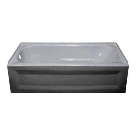
Porcher TETSU 60525 Operation and maintenance manual

754550-100 Rev. B
1
THANK YOU...
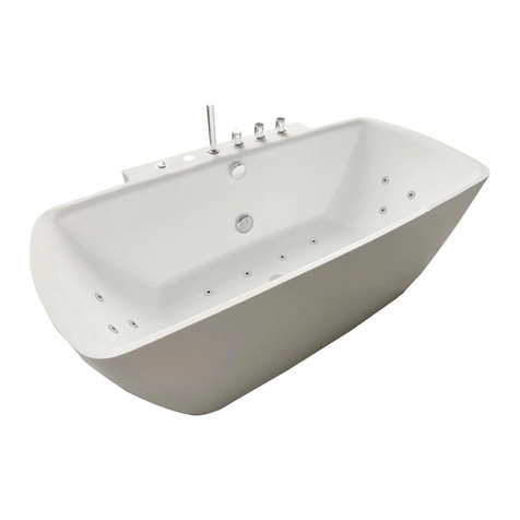
for selecting an Porcher bath. Your new bath is shipped to you after careful inspection. The Air Massage
System is completely assembled with air pump, motor and system piping. All you need to finish the installation
are your selected fittings and electrical connections for an Air Massage System.
To ensure maximum performance and pleasure from this product, please follow the instructions and cautions.
© Porcher 2010
All product names listed herein are trademarks of Porcher unless otherwise noted.
FOR AFTER-SALES SERVICE CALL 1 (800) 359-3261 WEEKDAYS.
TETSU 5-1/2' x 32" MODEL 60525
TETSU 5-1/2' x 36" MODEL 60545
LUTEZIA 5-1/2' x 36" MODEL 60645
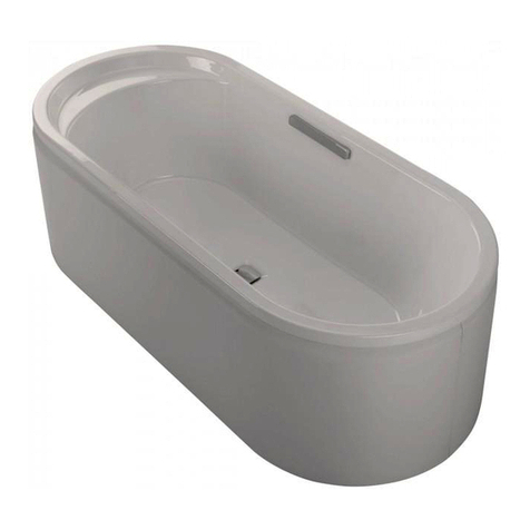
ARCHIVE 5-1/2' x 36" OVAL MODEL 60745
INSTALLATION INSTRUCTIONS
OPERATION AND MAINTENANCE
WARRANTY
ATTENTION INSTALLER:
Please deliver this manual to homeowner.

2
754550-100 Rev. B
TABLE OF CONTENTS:
Cover
................................................................................................Page 1
Table of Contents
..............................................................................Page 2
Safety Instructions Notice.................................................................Page 3
General Installation Information..............................
...........
...............Page 4
Tub Specifications.........................................................
...................
.Page 5
Roughing-in References............................................
.......................
Page 6 - 8
Installation and Framing Instructions........................
..........................
Page 9
Under Deck Mounting Instructions....................................................Page 10
Electrical Instructions
.....................................
....................
..............
..Page 11
Remote Air Blower Location Option..................................................Page 12
Free Standing Tubs............................................
......
................
........
.Page 13 - 14
Drain Assembly and Installation Instructions...........
.......................
...Page 15 - 19
Post Installation Instructions.............................................................Page 20
Operation: Bath with Lights...........................
....................................
.Page 21
Air Massage System.........................................................................Page 22
Operation: Air Bath............................................................................Page 23
Operation: Air Bath with Lights..........................................................Page 24 - 25
Cleaning and Maintenance...................
.........................................
....Page 26
Warranty......................................
.....................................................Page 27

754550-100 Rev. B
3
IMPORTANT SAFETY
INSTRUCTIONS
READ AND FOLLOW ALL INSTRUCTIONS!
!
!
!
!
!
!
WARNING: Risk of personal injury. Do not permit children to use this bathtub without adult supervision. Never drop or
insert any object into any opening. Do not operate this unit without the guard over the suction fitting.
WARNING: Risk of electric shock. Do not permit electrical appliances near any bathtub when bathtub contains water.
WARNING: Risk of hyperthermia and possible drowning. People using medications and/or having adverse medical
history should consult a physician before using this product.
WARNING: Risk of personal injury. Do not overfill bathtub before entering. Entering tub when filled more than 2/3 can
cause overflow and slippery conditions. Exercise caution when entering and exiting.
WARNING: No Food or Alcoholic Beverages. Use of your bathtub immediately after meals is not recommended. Avoid
alcohol consumption before or during bathing. Alcoholic beverages can cause drowsiness or hyperthermia resulting in loss of
consciousness or even drowning.
WARNING: Pregnancy. If you are or think you may be pregnant, consult your physician before using the bathtub.
Use this unit only for its intended use as described in this manual.
Do not use any attachments not recommended by Porcher.
The unit must be connected only to a supply circuit that is properly protected by a ground-fault circuit-interrupter (GFCI). Such a
GFCI should be provided by the installer and should be tested on a routine basis. To test the GFCI, push the test button. The
GFCI should interrupt power. Push the reset button. Power should be restored. If the GFCI fails to operate in this manner, the
GFCI is defective. If the GFCI interrupts power to the bathtub without the test button being pushed, a ground current is flowing,
indicating the possibility of an electric shock. Do not use this air bath. Disconnect the air bath and have the problem corrected by a
licensed electrician before using.
SAVE THESE INSTRUCTIONS

4
754550-100 Rev. B
General Installation Information
Carefully uncrate and inspect your new bath for any shipping damage. If such damage is found, report it to your
vendor immediately. After inspection and during installation, protect the bath from construction damage. Before
installation, and before enclosing with wallboard, tile, etc., the bath must be filled with water to check for leaks that
may have resulted from shipping damage or mishandling! Fittings (bath filler, shower arm, etc.) are not provided with
the bath and must be ordered separately. Framing and enclosing materials are provided by others. Follow test
procedures carefully.
ATTENTION INSTALLER!
THIS TUB MUST BE TESTED FOR OPERATION AND LEAKS PRIOR TO ENCLOSURE OF SURROUNDING
AREAS. FAILURE TO DO SO WILL VOID WARRANTY. THIS TUB WAS WATER TESTED AT THE FACTORY AND
FOUND TO BE FULLY OPERATIONAL AND LEAK FREE PRIOR TO SHIPPING. FREIGHT HANDLING AND JOB
SITE EXPOSURE MAY HAVE DETERIORATED THE TUB’S CONDITION. IT IS THE RESPONSIBILITY OF THE
INSTALLER TO THOROUGHLY TEST THE UNIT PRIOR TO INSTALLATION. TUBS ARE INTENDED FOR
INDOOR USE ONLY.
TEST PROCEDURES:
1. Place the tub on a flat surface such as a driveway.
2. Seal the drain with tape.
3. Fill tub and allow tub to stand for five minutes without the blower running. Examine all fittings carefully for
leaks. NOTE: The overflow is a plumbing device designed to prevent water from reaching a certain level in your
tub. DO NOT, under any circumstances, tape off or block the overflow in any way. Any controls located above the
normal water line are designed to be water resistant, not waterproof. The controls will not leak under normal
usage, however, they are not warranted against leaks when improperly used or subjected to conditions for which
they are not designed.
4. Plug the blower into a 110V GFCI outlet. Start the blower and check all fittings for leaks.
5. Check that all optional equipment is functioning properly and that the features on the tub match exactly what was
ordered.
6. If any leaks or operating problems are discovered, do not complete installation until problems are
resolved. Porcher will not be responsible for any costs involved with removing or reinstalling the tub, or
for the costs of any surrounding materials or labor.
If you have installation or warranty questions please do not return the unit to the place of purchase. Call 800-359-3261
Always protect tub from construction damage by using a protective cover. Damage, including chips and scratches
incurred at the jobsite is excluded from warranty but may be repaired by qualified technician at the owner’s expense.
Do not stand in the tub or store materials in the tub during construction. Do not store tub in temperatures below 32
degrees Fahrenheit. Proper waste and overflow installation is the responsibility of the installer. Porcher does not
warrant leaks associated with improper waste and overflow installation.
Access must be provided to air blower and/or electrical component on your tub.
The access panel(s) must have a minimum size of 16" x 14" (406 x 356mm)
for installation and future servicing of the equipment. Porcher, Inc. will not authorize any
service
unless clear access is available. Access from a crawl space or incomplete
access to
all
equipment may result in warranty claims being denied.
Check for availability of optional Porcher wall tiling bead (required for recess installation).
Protect all finished surfaces of the bathtub during construction and installation using a drop cloth.
754550-100 Rev. B
5
OD
X
Z
Y
For Air Baths:
1. Never handle the bath by the blower, piping or other equipment.
2. Make sure the manifold and airlines are protected when moving the tub into the house.
3. An access panel measuring 16" x 14" (406 x 356mm) must be provided for the blower for any future servicing.
4. The blower must not be insulated and must have sufficient air space to permit proper operation. Surrounding ambient air
temperature should be between 72°F and 86°F.
5. The heating element on your blower heats the air blown into the tub to prevent the water from cooling too quickly. It will
not, under any circumstances, reheat or maintain the temperature of bath water.
6. The area underneath and around the tub must be cleaned thoroughly before finalizing installation to prevent any particles
from entering the blower or being blown into the air jets.
7. Before filling the tub, clean installation debris and dirt from the interior of the tub. If necessary, use the soft brush
attachment of a vacuum cleaner.
8. Fill tub and test for proper operation and leaks. Note: The blower must be plugged into a GFCI protected outlet.
9. The drain supplied must be used. It is part of the Air Bath and the system will not function correctly without it.
List of Required Tools and Supplies
Tools Supplies Optional Components (not included):
• Level • Nails • Tile Bead Kits (P/N 751755-100)
• Tape Measure • Putty
• Pipe Wrench • Caulking (waterproof) Required Components:
• Slip Joint Pliers • 1 X 4 Stringers • Drain (included)
• Screw Driver • Drop Cloth • Bath Filler (not included)
• Standard Woodworking Tools • Cement, Plaster, Grout
• Personal Safety Equipment • Liquid Nails (Freestanding Modes Only)
• Caulking Gun
DECK TO C/L OVERFLOW
SPECIFICATIONS
TABLE 1
GENERAL SPECIFICATIONS AIR BATHS - DROP IN AND RECESS MODELS
Fore more details, see specification page per model at www.porcher-us.com
*note - on Air Baths the drain included with the tub must be used. The drain outlet is directly under the drain hole in the tub.
2-1/2"
64mm
50 lbs./ft2
40 lbs./ft2
48 lbs./ft2
54 lbs./ft2
Gallon to
Overflow
Product
Weight
Weight with
Water / Floor
Loading
Rough-In
Recess
A x C
Cut Out
Pier
G x F
Drain /
Overflow
Description
Tetsu™
5-1/2' x 32"
(140 x 813mm)
60525
Tetsu™
5-1/2' x 36"
(140 x 914mm)
60545
Lutezia™
5-1/2' x 36"
(140 x 914mm)
60645
Archive™Oval
5-1/2' x 36"
(140 x 914mm)
60745
X 17" (432mm)
Y 10-1/8" (257mm)
Z 7-1/8" (181mm)
X 17-1/4" (438mm)
Y 10" (254mm)
Z 5-1/4" (133mm)
X 17-3/8" (441mm)
Y 10" (254mm)
Z 7" (178mm)
X 17-3/8" (441mm)
Y 9-1/2" (241mm)
Z 6-3/8" (62mm)
64-1/2" x 30-1/2"
(1638 x 775mm)
64-1/2" x 34-1/2"
(1638 x 880mm)
64-1/4" x 34-1/2"
(1630 x 880mm)
Use Template
Provided
66" x 32"
(1677 x 813mm)
66-1/4" x 36-1/4"
(1682 x 920mm)
66" x 36"
(1677 x 914mm)
See Template
Dimensions
-Next Page-
85 lbs.
(39 kg.)
85 lbs.
(39 kg.)
85 lbs.
(39 kg.)
121 lbs.
(55 kg.)
78 gal.
(295 l.)
68 gal.
(260 l.)
84 gal.
(320 l.)
80 gal.
(300 l.)

6
754550-100 Rev. B
Cut Line
Tub Edge
35"
(889mm)
17-1/2"
(445mm)
1"
(25mm)
32-3/4"
(832mm)
Center of Drain
65-1/2"
(1664mm)
Full Length of Tub
63-1/2"
(1613mm)
Cut Hole Length
9-1/2" (241mm)
Center of Drain
16-1/4"
(413mm)
16-1/4"
(413mm)
16-1/4"
(413mm)
16-1/4"
(413mm)
16-1/4"
(413mm)
16-1/4"
(413mm)
16-1/4"
(413mm)
14"
(356mm)
14"
(356mm)
1-3/4"
(44mm)
7-1/4"
(190mm)
7-1/4"
(190mm)
6"
(152mm)
6"
(152mm)
6"
(152mm)
6"
(152mm)
6"
(152mm)
6"
(152mm)
6"
(152mm)
6"
(152mm)
6"
(152mm)
6"
(152mm)
Archive
Drop-In
Cutout
Template
1-3/4"
(44mm)

754550-100 Rev. B
7
Roughing In References
Soaker, Soaker with Lights, Air Bath, Air Bath with Lights
-see appropriate sections for details - support soakers with bedding material, rim must NOT support weight
66"
(1676mm)
46"
(1168mm)
112˚
3-3/4" (95mm)
3-3/4"
(95mm)
32"
(813mm)
47-1/2"
(1207mm)
1-1/2"
(38mm) 1-1/2"
(38mm)
19-5/8"
(488mm)
16-5/8"
(422mm)
18-7/8"*
479mm)
10-1/8" (257mm)
2-5/8"
(67mm)
18-1/2"
(470mm)
17-1/2"
(445mm)
20-3/8"*
(518mm)
Tetsu 5-1/2' x 32"
(1676 x 813mm)
Model 60525
*For Air Baths Add 2-1/2" (64mm)
66"
(1676mm)
6" (152mm)
10"
(254mm)
3" (76mm)
36"
(914mm)
57"
(1148mm)
47-1/2"
(1207mm)
19-1/2"*
(495mm)
18-3/4"
(476mm)
16"
(406mm)
21"
(533mm)
18"*
(457mm)
3" (76mm)
55"
(1397mm)
115°
95°
Tetsu 5-1/2' x 36"
(1676 x 914mm)
Model 60545
*For Air Baths Add 2-1/2" (64mm)
*For Air Baths Add 2-1/2" (64mm)*For Air Baths Add 2-1/2" (64mm
Lutezia 5-1/2' x 36"
(1676 x 914mm)
Model 60645
65-3/4"
(1670mm)
4" (102mm)
4"
(102mm)
36"
(914mm)
58-1/4"
(1480mm)
47"
(1194mm)
19-3/4"
(502mm)
17"
(432mm)
4"
(102mm)
10" (254mm)
20-1/2"*
(521mm)
17-7/8"*
(454mm)
Archive 5-1/2' x 36" Oval
(1676 x 914mm)
Model 60745
114°
9-1/2"
(241mm)
23"
(584mm)
35"
(889mm) 27"
(686mm)
65-1/2"
(1664mm)
32-3/4"
(832mm)
39"
(991mm)
19"*
(483mm)
21-3/8"*
(543mm)
2-3/8"
(60mm)
55"
(1397mm)
58-1/4"
(1480mm)
3-3/4" (95mm)
ANGLE OF SIDES - 94˚
47"
(1194mm)
25"
(635mm)
ANGLE OF SIDES - 95.5˚
ANGLE OF SIDES - 96˚
3-3/4" (95mm)
3-3/4" (95mm)
47"
(1194mm)
23"
(584mm)
ANGLE OF SIDES - 95.5˚
48"
(1219mm)
109˚

8
754550-100 Rev. B
50" (1270mm)
9-1/2" (241mm)
23"
(584mm)
35"
(889mm) 27"
(686mm)
65-1/2"
(1664mm)
32-3/4"
(832mm)
57"
(1148mm)
47-1/2"
(1207mm)
18-3/4"
(476mm)
16"
(406mm)
55"
(1397mm)
66"
(1676mm)
6" (152mm)
10" (254mm)
3"
(76mm)
36"
(914mm)
3" (76mm)
36"
(914mm)
58-1/4"
(1480mm)
47"
(1194mm)
19-3/4"
(502mm)
17"
(432mm)
4"
(102mm)
10" (254mm)
47-1/2"
(1207mm)
19-5/8"
(488mm)
16-5/8"
(422mm)
58-1/4"
(1480mm)
66"
(1676mm)
3-3/4" (95mm)
3-3/4"
(95mm)
32"
(813mm)
10-1/8" (257mm)
3-3/4" (95mm)
Roughing In References
Freestanding Models
-see appropriate sections for details
8" (203mm)
23"
(548mm)
Tetsu 5-1/2' x 32"
(1676 x 813mm)
Model 60525
freestanding tubs use wall-mounted or freestanding faucets. The waste and overflow assembly
is concealed between the walls of the tub, eliminating the need for a decorative exposed drain kit.
Dotted Line Represents Bathing Well
Measurements are ± ½" (13mm) and are subject to change without notice.
Data herein supersedes all previous prior to publication date shown below.
A - For Air Equipped Tubs Only
Do Not drill in this area
Air Component will be
damaged.
A
24"
(610mm)
22"
(559mm)
115°
95°
Tetsu 5-1/2' x 36"
(1676 x 914mm)
Model 60545
Freestanding tubs use wall-mounted or freestanding faucets. The waste and overflow assembly
is concealed between the walls of the tub, eliminating the need for a decorative exposed drain kit.
Dotted Line Represents Bathing Well
Measurements are ± ½" (13mm) and are subject to change without notice.
Data herein supersedes all previous prior to publication date shown below.
Lutezia 5-1/2' x 36"
(1676 x 914mm)
Model 60645
Freestanding tubs use wall-mounted or freestanding faucets. The waste and overflow assembly
is concealed between the walls of the tub, eliminating the need for a decorative exposed drain kit.
Dotted Line Represents Bathing Well
Measurements are ± ½" (13mm) and are subject to change without notice.
Data herein supersedes all previous prior to publication date shown below.
Archive 5-1/2' x 36" Oval
(1676 x 914mm)
Model 60745
Freestanding tubs use wall-mounted or freestanding faucets. The waste and overflow assembly
is concealed between the walls of the tub, eliminating the need for a decorative exposed drain kit.
Dotted Line Represents Bathing Well
Optional one-piece pedestal base.
Measurements are ± ½" (13mm) and are subject to change without notice.
Data herein supersedes all previous prior to publication date shown below.
35-1/4" W
(895mm)
3" H
(76mm)
21-3/8"
(543mm)
21"
(533mm)
43" (1092mm)
23-1/2"
(597mm)
4"
(102mm)
4"
(102mm)
65-3/4"
(1670mm)
23"
(548mm)
3-3/4" (95mm)
3-3/4" (95mm)
17-1/2"
(445mm)
39"
(991mm)
55"
(1397mm)

754550-100 Rev. B
9
TYPICAL
INSTALLATION
DROP IN AND RECESS MODELS
INSTALLATION AND FRAMING OPTIONS
The variety of installations possible for these products may require framing procedures
other than those shown. Locate studs as required. Ensure roughing-in dimensions are proper,
plumb and square. Provisions must be made in all installations for an access opening for servicing
the air blower and controls. It is strongly recommended that an additional opening be provided for
access to the drain components and fixtures. The apron should not be used as the primary access
opening.
1. Position the bath into the installation opening and level the deck in both directions. Mark the
final position of the underside of the deck by tracing a line on to the studs (see Figure 1)
The bath must be supported by bedding compound underneath the entire length of the bath.
If your bath arrived with the pre-leveled foam base, no bedding compound is necessary (although
some bedding compound may be needed to level the tub if the sub-floor is not perfectly level).
2. Remove the bath and attach a 1 x 4 stringer to the studs, with the top of the stringer touching the
traced line.
The rim of the bath must not support weight.
Additional instructions for Air Baths:
3. Install supplied cable drain components to the air massage bath according to the enclosed drain
installation instructions. Before replacing your air bath for final installation, be certain that an opening
has been provided in the sub-floor for the drain. See the roughing-in drawing for suggested opening
size (shadowed) and location dimensions. The drain/overflow of the bath extends below the bottom of
the bath. Note that this requires a cutout in the floor.
4. Replace air massage bath, using bedding compound as needed to completely support and level
the bath.
The rim of the bath must not support weight. Any finish material such as tile or wall board must be
self-supporting if it contacts the deck of the bath.
14"
(356 mm) 14"
(356 mm)
16"
(406 mm) 16"
(406 mm)
UNLESS AN ACCESS OPENING OF AT LEAST 16" X 14" (406 X 356mm)
IS PROVIDED, WARRANTY SERVICE WILL NOT BE PERFORMED.IS PROVIDED, WARRANTY SERVICE WILL NOT BE PERFORMED.
UNLESS AN ACCESS OPENING OF AT LEAST 16" X 14" (406 X 356mm)
IS PROVIDED, WARRANTY SERVICE WILL NOT BE PERFORMED.
D*
A
C
D*
AS DESIRED
C
E
CUTOUT
F
CUTOUT
AS DESIRED
MOUNTING
SURFACE
WATERPROOF
SEALANT
BATH ACCESS PANEL MUST BE LOCATED
ON THE SAME SIDE AS THE MOTOR.
ALLOW OPEN FRAMING ON PUMP/MOTOR
END FOR SERVICE.
TYPICAL PIER TYPE INSTALLATIONTYPICAL RECESS INSTALLATION
ACCESS PANEL MUST BE LOCATED
ON THE SAME SIDE AS THE BLOWER.
ALLOW OPEN FRAMING ON
BLOWER END FOR SERVICE.
NOTE:
FRONT EDGE
OF BATH MUST
BE SUPPORTED
BY STUD WALL OR
PORCHER APRON KIT
FIGURE 1
D
WALLBOARD
ADHESIVE
LEVELING STRINGER
1" X 4" (25 x 102mm)
(not for support)
NOTE: Tile bead kit not included
and must be purchased separately.
BATH
SEALANT
TILE
BEAD
STRIP
TILE
Refer to Specification Sheets and Diagram for appropriate dimensions.
* Dim D - See Roughing-In References Page
NOTICE:
DO NOT BUILD THE SURROUNDING STRUCTURE BEFORE RECEIVING YOUR AIR BATH.
STRUCTURE MEASUREMENTS SHOULD BE VERIFIED AGAINST THE ACTUAL AIR BATH
RECEIVED TO ENSURE PROPER FIT.

10
754550-100 Rev. B
Please note that care must be taken to protect the surface of the tub during all aspects of the installation.
Do not drill or cut the bath deck with the tub directly beneath it as damage to the tub may result.
1. Install the tub per the installation instructions provided with the unit.
2. Prepare the bath deck support structure per the local codes. Note - the bath deck must be self supporting.
3. Cut bath deck to your specifications. A professional solid surface installer should template product on site
for exact cut out dimension.
4. Replace the bath deck and secure it into place.
5. Apply additional sealant along the tub and bath deck interface as necessary to ensure a watertight seal.
6. Remove excess sealant per the manufacturer's instructions.
Finished bath deck surface material must be
self-supporting and secured per local codes
Tub support structure per installation
instructions provided with the tub
Bath deck support material
Bathtub
Waterproof
Sealant
UNDER DECK MOUNTING INSTRUCTIONS

754550-100 Rev. B
11
ELECTRICAL INSTALLATION INSTRUCTIONS
All wiring must be performed by a licensed electrician in accordance with the national electrical code and all other applicable codes.
WARNING: When using electrical products, basic precautions should always be observed, including the following:
1. DANGER: RISK OF ELECTRIC SHOCK! Connect only to a circuit protected by a ground-fault circuit interrupter.
2. Permit access for servicing blower (if equipped) as noted.
3. All building materials and wiring should be routed away from the pump body and heater (if equipped).
ELECTRONIC ACTIVATED LIGHTS ONLY SYSTEM (1 BUTTON PANEL)
ELECTRONIC ACTIVATED AIR BATH WITH LIGHTS (5 BUTTON PANEL)
120V, 60HZ
15A GFCI
ELECTRICAL
FEED
GFCI
ELECTRONIC ACTIVATED AIR BATH (4 BUTTON PANEL)
120V, 60HZ
15A GFCI
ELECTRICAL
FEED
GFCI
120V, 60HZ
15A GFCI
ELECTRICAL
FEED
GFCI

12
754550-100 Rev. B
REMOTE BLOWER LOCATION OPTION
IMPORTANT! It is not necessary that the blower motor be relocated. This option is provided for the case that a particular
installation makes this effort practical.
NOTE: Relocating blower motor from factory installed location, see photo 1, will require disassembly of air blower from mounting
board. Keep all hardware for reattachment at new location. Additional hardware will be required depending upon final
desired position of air blower. Follow all instructions listed below.
NOTE: Installing the blower in a remote location will reduce the system efficiency.
NOTE: Relocating a blower motor still requires a service access for the blower.
NOTE: All materials needed for the relocation must be supplied by the installer. This includes ordering a longer control panel
cable (754025-0073A), a longer flexible blower hose (753960-2030A), and up to two lighting cable extensions for combo
models (754512-0070A).
A separate circuit, which must be protected by the Ground Fault Circuit Interrupter (GFCI), is required in the remote location.
Electrical connections should be performed by a licensed electrician.
The blower motor must be located within 12 feet of rigid piping from the bath air manifold. This limitation is for the total pipe length
and applies to any direction changes and elbows. There can be no more than six changes of direction. There should be as few
direction changes as possible and the piping installation must meet all requirements of local plumbing and building codes.
Disconnect the blower from the flexible hose as shown in photo 2. Do NOT remove the check valve manifold that is mounted to the
underside of the air bath. The manifold MUST remain mounted above the tub overflow level as shown in 2.
Replace the flexible hose shown in photo 2 with the longer flexible hose (P/N 753960-2030A) using the existing hope clamps.
NOTE: Do NOT remove the original cable coming out of the blower. Instead, plug the longer cable (P/N 754025-0073A)
into the existing cable that is coming out of the blower as shown in photo 3. Then plug the remaining end of the
longer cable into the control panel which remains on the tub wall.
1.
TYPICAL VIEW
2.
TYPICAL VIEW Do NOT move check
valve manifold
3.
TO CONTROL PANEL
754025-0073A CABLE
(INCLUDES ADAPTER
BOX SHOWN)
TO BLOWER
EXISTING
CABLE

754550-100 Rev. B
13
General Information
Rough in dimensions For critical dimensions, we suggest taking the measurements of the actual tub on
site. All printed specifications are +/- 1/2 inch (13mm) and subject to change without notice.
Access panel- A removable access panel is located on the drain side (rear) of the bath. It provides access
for installation of the waste and overflow. It is held in place by covered stainless steel screws. On freestanding
air bath models, keypad wire and hose exit the bottom of the bath.
Pedestal Base - The optional pedestal base available on some models does not raise the height of the tub, as the
tub actually sits down into the base. The base does, however, extend beyond the top rim of the tub by approximately
1" (25mm). Use care when selecting your free-standing faucet, ensuring that the reach of the spout is adequate so
that no modification to the pedestal base will be necessary. If wall mounted fixtures are being used, again be careful
to ensure the spout will extend out far enough to clear the tub flange and the falling water will not hit too high up on
the side wall of the tub and splash. It may be necessary to omit or trim the baseboard or molding to allow the tub
to sit close to the wall. Please note: The pedestal base is not
symmetrical; if it does not fit, rotate the base 180°.
Fixtures
No fixtures can be mounted on the tub deck freestanding tubs. Floor or wall-mounted fixtures
are required. (Except for Model 60545)
Wall-Mounted - The position of the tub and the reach of the spout are critical. Pay special attention to the
spout reach when choosing your fixtures. Be careful to ensure the spout will extend out far enough to clear
the tub flange and the falling water will not hit too high up on the side wall of the tub and splash.
Floor-Mounted - Some freestanding fixtures must be anchored to the tub drain for stabilization. The waste
and overflow on freestanding tubs are concealed under the access cover so anchoring to the overflow pipe
(or tub structure) is not possible. Many kits (with minor modification) can be mounted to the wall (rather than
the drain pipe) for stabilization.
Basic Installation Procedure
• Determine final location of tub. Tub will sit on top of finished flooring.
• Ensure location is structurally sound, flat and level.
• Remove access panel to gain access for waste and overflow installation. Be careful not to damage the
access panel during installation.
• Roll tub onto front face, being careful not to damage the acrylic finish. Use packing blanket or other suitable
material to protect the surface of the tub.
• Install waste and overflow.
• Using two 2' x 4's to elevate the tub above the floor, align the tub so that the drain lines up with the P-trap in
the floor. DO NOT LET THE TUB REST ON THE DRAIN PLUMBING.
• Apply a 3/8" bead of Liquid Nails to the bottom of the tub to adhere it to the floor.
Use care not to allow adhesive to get on the outside surface of tub or surrounding floor area. Wipe any
excess immediately with a soft, damp cloth.
• Carefully remove the 2' x 4' supports and lower the tub to the floor, making sure that the drain drops into the
P-trap.
• Check that the drain is properly aligned, complete drain installation and reinstall the access cover.
• Allow to set for 24 hours before using.
Freestanding Tubs

14
754550-100 Rev. B
Waste and Overflow
• Due to limited space between the inner and outer tub shells, use care when selecting your drain kit. Use a cable
driven or toe-tap style. If you ordered your bath with an air system, you MUST use the drain kit included. If access is
available from below during the final installation, it is easier to make precise adjustments in the final location of the tub.
• Remote Mounting Blower - Due to the limited space between the inner and outer shells of the freestanding tubs,
the blower must be remote mounted. In addition to the air hose, there are two electrical connections between
the tub and the blower. Both electrical connections and the air hose exit through the bottom of the bath. It is
always desirable to remote mount the air blower as close to the tub as possible to minimize the loss of heat.
Pipe insulation may be used on the blower hose to minimize heat loss.
NOTE: Relocating a blower motor still requires a service access for the blower.
NOTE: All materials needed for the relocation must be supplied by the installer. This includes ordering a longer control
panel cable (P/N 754025-0071A).
A separate circuit, which must be protected by the Ground Fault Circuit Interrupter (GFCI), is required in the remote
location. Electrical connections should be performed by a licensed electrician.
ADDITIONAL INSTRUCTIONS FOR FREESTANDING AIR BATHS
All freestanding air baths may be installed in the center of the room. Keep in mind that the placement of the blower
can be challenging or problematic. All models have a built in access panel for drain installation that you may prefer to
place on the less visible side of the bath. Although each installation may vary, Porcher offers two solutions to blower
placement.
a) Adjacent to the tub: A decorative box to hide the blower may be custom built on site. The box
should always provide access for future servicing of the blower, as well as the required minimum
5" x 7" (127 x 178mm) ventilation panel.
b) Remote mounting the blower: The blower may be remote mounted up to 8' (2438mm) from the bath. The
air hose leading to the blower may be installed under the floor and the blower located inside a
utility or linen closet. Use care not to crush or restrict the airflow in the line in any way. The blower
may also be located underneath the tub. In either case, access to the blower must be provided
for any future service.
1. Disconnect the air hose from the blower and use the provided clamps and coupling to attach
extension hose.
2. Reconnect hose to blower.
3. The wires leading from the keypad to the blower are standard 6' (1829mm) in length. Up to 12' (3658mm) is
available upon request. The wires on the sensors are 10' (3048mm) in length standard.
4. Secure blower using wood screws through the mounting feet.
Note: Pipe insulation may be used on the air hose to help retain warmth from the blower. Do not use insulation
within 8" (203mm) of the blower. The blower needs sufficient air space surrounding it for circulation. The blower requires
a separate 110VAC, 15 amp GFCI circuit.
Freestanding Tubs
(continued)

754550-100 Rev. B
15
AIR BATH DRAIN INSTALLATION - ALL AIR BATHS
NOTE: All Porcher Air Bath configurations include a drain. Other drains cannot be used.
NOTE: Include a 9" (229mm) wide by 18" (457mm) long cut-out in floor for drain.
DRAIN CONNECTION AND
SYSTEM TEST
(before installing bath)
With supplied cable drain assembled to
bath, connect drain outlet to waste line in
accordance with the drain assembly
instructions. Tighten all drain joints
securely. Check the couplings and make
sure they are hand-tight. Clean the air bath
and fill with water to a point 2" (51mm) below
the overflow. Recheck the couplings and
make certain that they are not leaking.
(Although the couplings are factory
tightened and inspected, some loosening
may have occurred during transit.) Make
sure the air bath is connected to the
electrical supply and turn the air bath on.
Check for leaks around all piping
connections while the air bath is running.
DRAIN STOPPER
WITH
ADJUSTABLE
BOLT
METAL STRAINER
BOLT
DRAIN WASTE
FLANGE
METAL
STRAINER
FLAT RUBBER
GASKET
PLASTIC DRAIN BASE
OVERFLOW
ESCUTCHEON
OVERFLOW
ASSEMBLY
WEDGE
GASKET
SET
SCREW
DRAIN ACTUATOR SHAFT OVERFLOW
RETAINER
OVERFLOW
ASSEMBLY
VERTICAL
FLEX PIPE
CLOSE OPEN
OVERFLOW NUT WITH O-RING
AIR BATH NUT
WITH WASHER
AND GASKET
HORIZONTAL
DRAIN PIPE
PLASTIC
DRAIN BASE
90° ELBOW
AIR BATH DRAIN ILLUSTRATION

16
754550-100 Rev. B
DRAIN CONNECTION
1. Remove and identify all drain components as defined in air bath drain illustration.
2. Find 1" schedule 40 PVC pipe, 12" length, HORIZONTAL DRAIN PIPE.
Cut pipe to nominal 5" length and mark as “horizontal pipe”, drain to elbow section.
3. Find 1" diameter VERTICAL FLEX PIPE. Mark as “vertical pipe”,
drain to elbow section.
4. Install drain from below unit through opening as shown in photo A.
5. Apply 3 or 4 pea sized dabs of 100% silicone sealant to bottom waste drain flange and press flat rubber gasket into place
as shown in photos Band C.
6. Apply 1/8" continuous bead of 100% silicone sealant to flat rubber gasket as shown in photo D. Set aside and be sure not to
disturb silicone bead.
7. Apply 1/8" continuous bead of 100% silicone sealant to back side to metal strainer as shown in photo E. Press
Strainer retaining bolt into metal strainer and insert into drain hole of acrylic bath.
A.
B. C.
D.
E.

754550-100 Rev. B
17
DRAIN CONNECTION continued...
8. Have assistant take drain assembly from step 6 and place over back surface of drain hole to engage the metal strainer bolt.
Secure plastic drain base to metal strainer in drain opening using nut driver shaft. DO NOT OVER TIGHTEN! Carefully
remove excess silicone from acrylic surface as directed by silicone sealant directions.
9. From unit back side, overflow nut should be in alignment with overflow opening, as shown in photo F.
10. Slide air bath fitting nut, washer and gasket onto air bath fitting as shown in photos Gand H.
11. Assemble air bath fitting to plastic drain base as shown in photos I, J, Kand L. Hand tighten nut to create watertight joint.
12. Apply PVC cement to Horizontal Drain Pipe PVC and assemble to 90 degree elbow.
F.
G. H.
I. J.
K. L.
Overflow nut
O-ring
Air bath
fitting

18
754550-100 Rev. B
M.
N.
O.
P. Q. R.
DRAIN CONNECTION continued...
13. Disassemble overflow wedge gasket and chrome overflow retainer as shown in photo M.
14. Place overflow wedge gasket onto plastic overflow pipe flange with round raised rib surface contacting flange
as shown in photo N.
15. Tighten chrome overflow retainer onto drain overflow assembly pipe per photo O.
16. Apply PVC cement to barbed end of 90 degree elbow and insert vertical flex hose over barbs as shown in photo P.
17. Align vertical flex hose end of piping with top of barbed fitting located on the overflow fitting and mark the flex hose
to be trimmed as shown in photo Q.
18. Cut off excess vertical flex hose as shown in photo R.
19. Attach vertical flex hose to barbed fitting on overflow fitting by preheating tubing and/or soaping barbed fitting with
dish soap as shown in photo S.
S.

754550-100 Rev. B
19
DRAIN CONNECTION continued...
20. Align flat on drain actuator shaft with corresponding flat in chrome metal overflow escutcheon and tighten set screw to fix
overflow escutcheon in place per photos Tand U.
21. Rotate left and right lightly to feel stops in drain cable control. This opens and closes drain.
22. Place drain stopper into drain waste hole as shown in photo V.
23. The drain stopper should prevent water from draining out of tub when the escutcheon is in the fully counterclockwise
position as shown in photo W. Adjust the drainstopper bolt to obtain the best water seal in the tub.
24. Rotate Drain Escutcheon to clockwise stop. This should open drain, between 1/8" (3mm) and 1/4" (6mm), to allow water
to exit bath. If not adjust metal bolt in drain stopper to allow draining function, but not so high that drain will not seal when
closed to hold water during use. See photo X.
W.
T. U.
X.
V.

20
754550-100 Rev. B
POST INSTALLATION CLEAN-UP
Remove all construction debris from bath. Tile grout can be removed with a wooden Popsicle stick or tongue depressor.
Do not use wire brushes or any other metal implement on bath surface.
Post installation clean-up generally can be completed using warm water and liquid dishwashing detergent.
Stubborn dirt or stains may be removed using granular Spic and Span®mixed with water.
Painter's naphtha can be used to remove excess adhesives and/or wet oil-base paint.
AFTERCARE and CLEANING
• The high gloss surface is resistant to impact and chemicals and will retain its lasting luster with proper care and maintenance.
• Always fill the tub with temperate water. Excessively hot water may cause surface damage
• Clean after use with a mild liquid household detergent cleaner. Do not use Lestoil, Lysol Disinfectant (spray or concentrate),
or Lysol Basin, Tub and Tile Cleaner, Windex, Mr. Clean, Dow Disinfectant Bathroom Cleaner, or cleaning products in
aerosol cans.
HARSH CHEMICALS SHOULD NEVER BE USED ON ACRYLIC SURFACES.
• Do not use wire brushes, knives or sharp objects to remove stains, cigarette tar deposits,or other surface blemishes.
• Abrasive cleaners or powders must not be used, since they will dull the surface. If the glossy surface looses its sheen, dulled
areas can be restored by rubbing with a white “automotive type” polishing compound and waxing with a “liquid wax.”
•Do not wax areas where you walk or stand.
• Do not allow nail polish remover, acetone, dry cleaning fluid, paint remover or other solvents to come into contact with
the surface.
• Clean the surrounding surface immediately after using caustic drain cleaners.
• Burning cigarettes will damage the surface.
• Should damage to the fixture occur, repairs can be made quickly and easily.
Your distributor or builder can provide details.
• Do not permit drain cleaner to enter the circulation system.
This manual suits for next models
3
Table of contents
Other Porcher Bathtub manuals
Popular Bathtub manuals by other brands

DURAVIT
DURAVIT Cape Cod 700362 Mounting instructions

Kohler
Kohler K-12105 installation guide

Ella's Bubbles
Ella's Bubbles Deluxe AM3057 L owner's manual

JASON Hydrotherapy
JASON Hydrotherapy Designer AN-P Series owner's manual

Acquabella
Acquabella AKRON Maintenance and installation guide

PAA
PAA Opera quick start guide