INSTALLATION INSTRUCTIONS
60" x 32" Acrylic Air Bath
1107630-2-C
5 of 28
Questions? Problems? For additional assistance, please contact KALLISTA’s Customer
Service Department at 1-888-4-KALLISTA (1-888-452-5547) or kallista.com.
BEFORE YOU BEGIN
CAUTION: Risk of product damage. Do not lift the bath by the piping or blower motor, or use the piping or
blower motor for structural support of the bath.
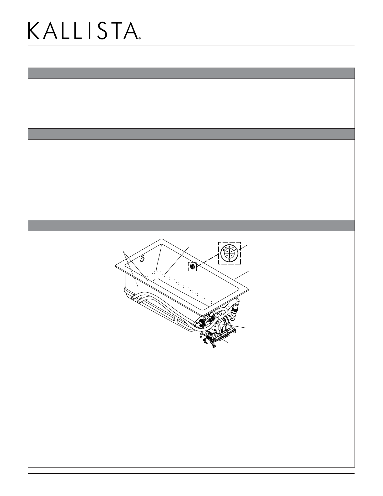
NOTE: This bath with airjets allows the blower motor and check valve to remain on the bath support board
(standard installation) as it is shipped or to be relocated to another location (remote installation). Refer to your
applicable installation throughout this installation guide.
For Standard and Remote Installations
We recommend this bath with airjets for drop-in or island installation, depending on the purchased model.
Inspect the bath for damage before you begin installation.
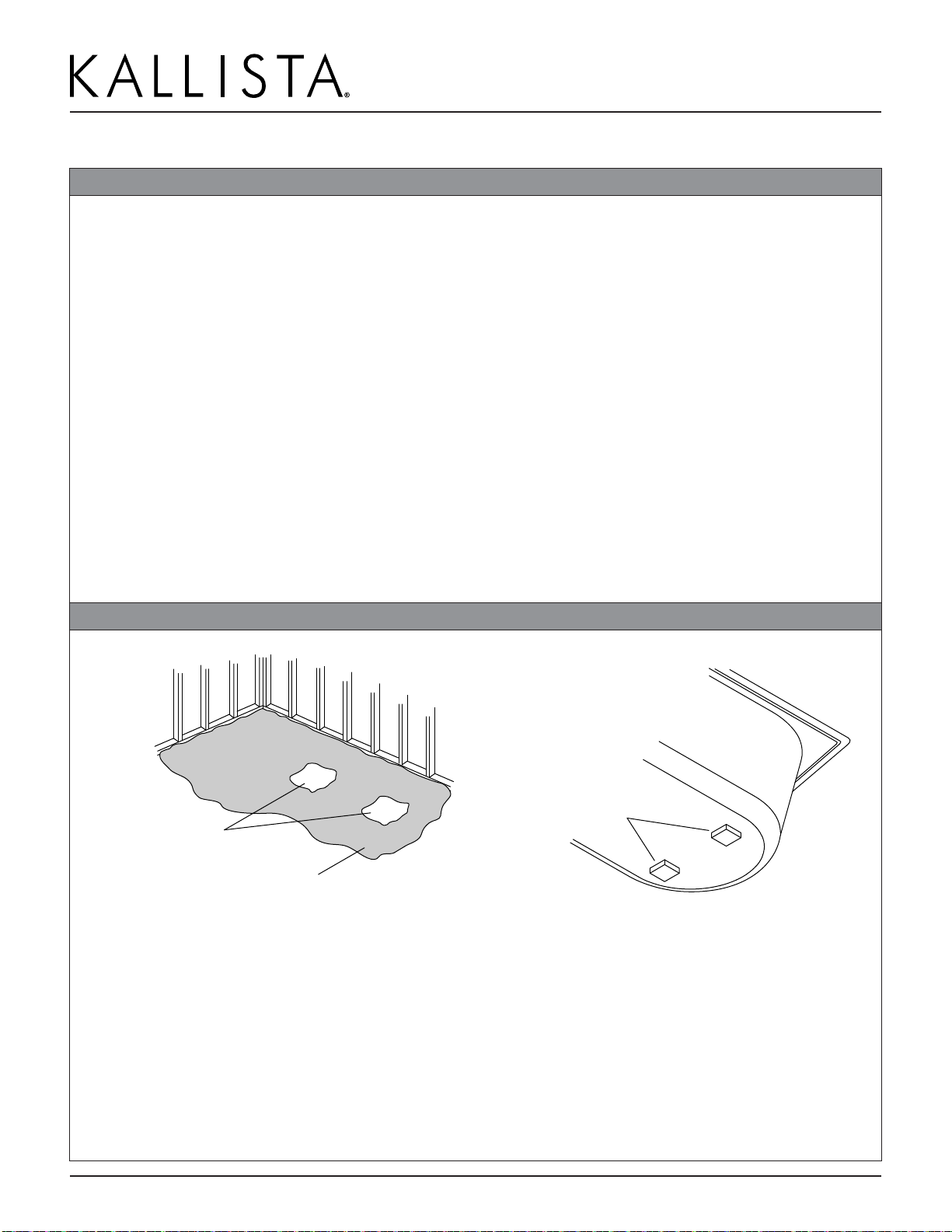
You must install this bath to an adequately supported, level subfloor.
Please read these instructions carefully to familiarize yourself with the required tools, material, and
installation sequences. Follow the sections that pertain to your particular installation. This will help you
avoid costly mistakes. In addition to installation instructions, read all operating and safety instructions.
The variety of installations possible with this bath may require framing procedures other than those
described in this manual.
Confirm adequate mounting and connection space for the faucet specified for your installation.
For Remote Installations
NOTICE: It is not necessary that the blower motor be relocated. The option is provided for the case that a
particular installation makes this effort practical.
For your convenience or accessibility, the blower motor and check valve can be mounted in a remote
location. Choose a space as close to the bath as possible to maximize bath performance. Plan and prepare
for the relocation. Pay attention to the following requirements and recommendations:
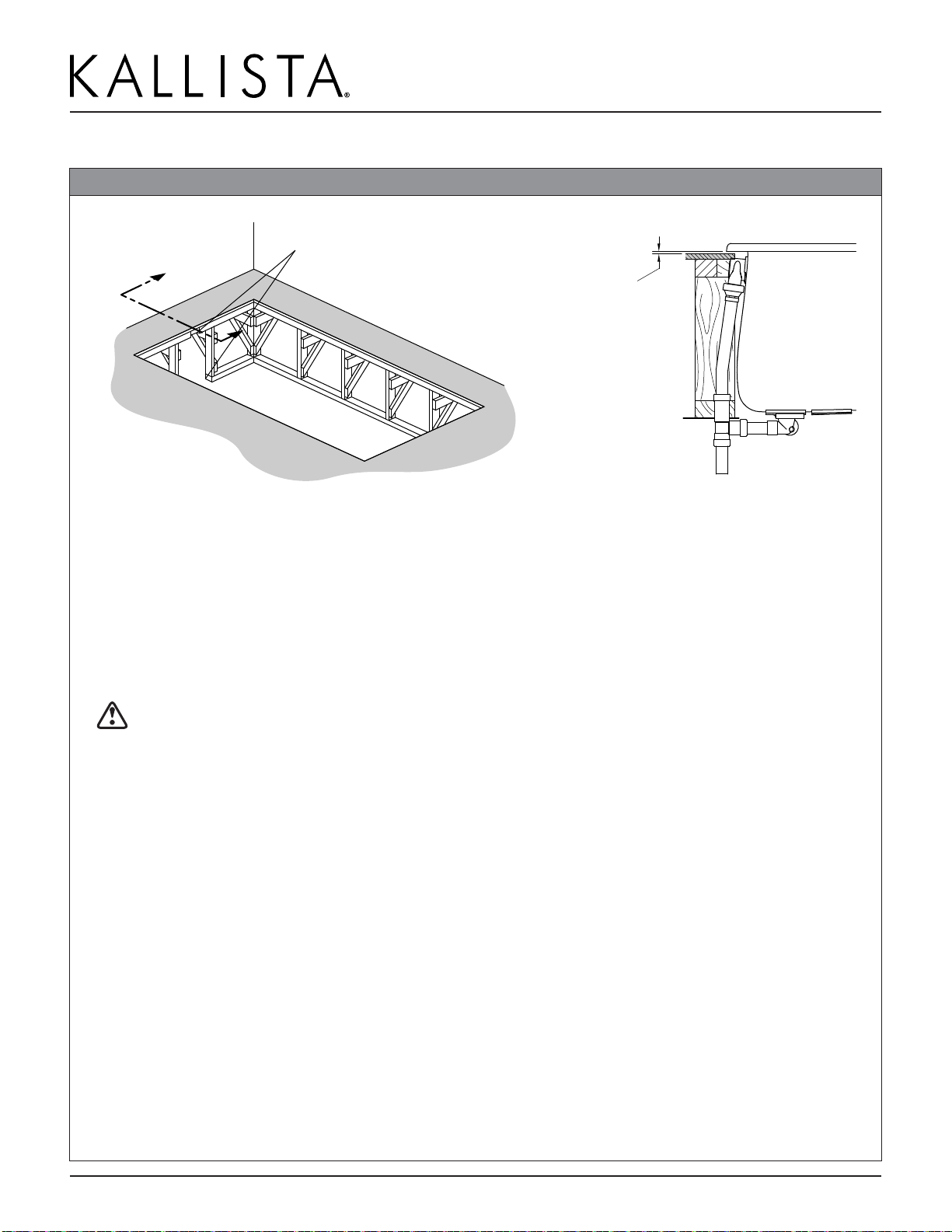
●The blower motor must be located within 15’ (4.6 m) of rigid piping from the bath air harness. This
limitation is for total pipe length and applies to any direction changes and elbows. There can be no more
than six changes of direction. There should be as few direction changes as possible.
●The blower motor must be mounted horizontally at least 2” (51 mm) above the floor. Do not mount the
blower motor with the blower motor discharge pointing up.
●The check valve must be relocated with the blower motor.At the new location, the check valve must
be no lower than 24” (610 mm) below the rim of the bath. The check valve must be within 12” (305 mm)
of the blower motor. The check valve must be oriented vertically with the flow arrow pointing up. DO
NOT relocate the control unit. The control unit must remain with the unit.
●Use 1-1/2” PVC or equivalent rigid piping. Use PVC unions or other means of making the installation
maintainable.
●The piping installation must meet the requirements of local plumbing or building codes. Ensure that the
installation does not reduce the fire rating of any walls. Piping must be supported at intervals along the
length in accordance with local codes.
●The blower motor must have adequate ventilation. Do not install the blower motor closer than 1” (25 mm)
from the wall or other objects. Provide a space of at least 15 cubic feet (.4 cubic meters) for cooling.