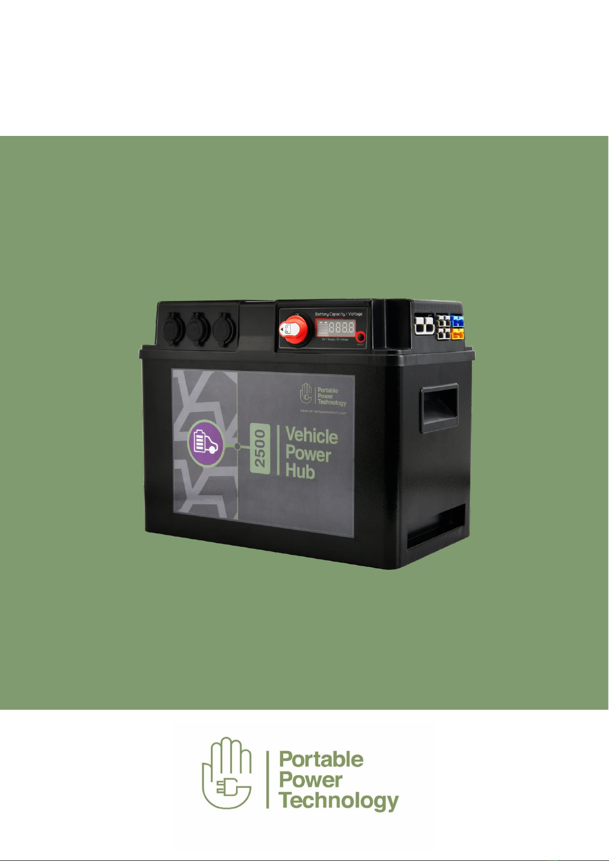
Portable Power Technology Vehicle Power Hub 1300 User manual

VEHICLE POWER HUB
Lithium Power Supply with in-built DC-DC charger and solar controller
USER MANUAL

01474 761 051
www.portablepowertech.com
2
CONTENTS
General Introduction 3
Product Overview 5
General Safety Instructions 6
General Precaution 7
Charging the Vehicle Power Hub 8
Operating Instructions 11
Multi-Function Display 13
Troubleshooting 14
Specifications 15
In the Box 16
Maintenance 17
Warranty 18
PLEASE READ THIS MANUAL BEFORE USE
Please note- this manual is relevant for models VPH1300, VPH2500 and VPH3800

01474 761 051
www.portablepowertech.com
3
GENERAL INTRODUCTION
Thank you for purchasing the Vehicle Power Hub.
The Vehicle Power Hub is a fully integrated solution combining lithium battery, in vehicle
DC-DC battery charger, integrated MPPT solar controller, 12VDC and USB outputs in a
single portable and movable box - Plug and play input and output Anderson connectors
make install safe and easy and with supplied cables enable fast connection and removal
from the vehicle when required.
The Vehicle Power Hub uses IEC certified Lithium batteries (LiFePo4), meets transport
requirements (UN38.3 and MSDS) and is CE certified.
Features
Portable - the clean and safe Lithium (LiFePo4) battery provides high energy storage - burn
less fuel and reduce CO2 emissions when running high loads for long periods. Fast,
efficient in vehicle charging means less idling is required to maintain loads.
➢Flexible charging options from high Power AC charger (up to 40A), integrated 30A DC-DC
charger for connection to alternator (inc EU6) and solar input up to 30A utilising the on
board solar MPPT controller
➢Plug and play Anderson connections provide multiple input/output configuration enabling
fast and easy deployment
➢Up to 250A DC output for direct connection to power inverter (up to max 2000W)
➢Strong metal and ABS case with easy to install fixing system
➢LCD control panel provides battery status and voltage
➢Built in multi safety protection from BMS, battery isolator, fusing and circuit breaker
➢2 x USB output and 2 x 12Vdc 10A sockets for device charging and powering 12V loads
directly

01474 761 051
www.portablepowertech.com
4
CHARGE THE VEHICLE POWER HUB NOW
Built-in ultra-high capacity lithium-ion battery pack. Before using or storing, please charge the
Vehicle Power Hub by the lithium-ion AC charger (supplied) until it’s fully charged. Don’t leave the
Vehicle Power Hub stored for extended periods of time without being charged. For long cycle life
the best thing for any battery is to use it and charge it

01474 761 051
www.portablepowertech.com
5
PRODUCT OVERVIEW
ADC ISOLATOR SWITCH
BMULTI FUNCTION DISPLAY
CEXTERNAL DC12V INVERTER OUTLET
D50A INPUT/OUTPUT
EIN-VEHICLE CHARGE INPUT (BLUE)
F12V SOLAR INPUT (YELLOW)
GUSB 5V 2 X 2.1A
HDC 12V 10A SOCKET
IIGN SIGNAL CONNECTION
JCARRY HANDLES
KSTRAPPING POINT
LDISPLAY ON/OFF
A
B
C
D
E
F
G
H
I
J
K
L

01474 761 051
www.portablepowertech.com
6
GENERAL SAFETY INSTRUCTIONS
Safety Instruction
As dangerous voltage and high temperature exist within the Vehicle Power Hub, only qualified and
authorized maintenance personnel are permitted to open and repair.
This is a maintenance free product –Removal of the lid may only be required to change a fuse –
seek approval from PPT Technical Team if required
Please make sure the Vehicle Power Hub (DC isolator) is turned off before opening and servicing.
This manual contains information concerning the storage and operation of the Vehicle Power Hub.
All relevant parts of the manual should be read prior to the operation.
Any operation against safety requirement or against design, manufacture, safety standard will be
out of manufacturer warranty.
The manufacturer accepts no liability for damage in the following cases:
* Damage to the product resulting from improper use, mechanical
influences and incorrect connection voltage.
* Alterations to the product without express permission from the
manufacturer.

01474 761 051
www.portablepowertech.com
7
GENERAL PRECAUTION
Energized Equipment –Electrical Shock and Explosion Hazards
➢Do not submerge in liquid or operate in wet environments. Device
is not waterproof or water resistant. Operate in dry environments
only.
➢Do not operate in flammable or explosive environments.
➢Do not operate if the unit is damage in any way including loose electronics or if charging
cords are frayed or wires are exposed.
➢Do not place foreign objects inside the power outlets or ventilation holes.
➢Always keep and use the device out of the reach of children.
➢Do not open the unit without permission and professional instruction.
➢Do not put fingers or hands into the device.
➢Do not attempt to replace the internal battery cells.
➢Do not power any DC device >250A for risk of main switch protection.
➢Please secure the device properly, when it’s stored or used.
➢Never connect positive terminal of Anderson plugs with negative terminals on the Vehicle
Power Hub
➢Only use the device between the temperature of -10°C to +50°C (-14°F to +122°F).

01474 761 051
www.portablepowertech.com
8
CHARGING THE VEHICLE POWER HUB
THE THREE WAYS TO CHARGE
Charging from AC Charger
Vehicle Power Hub 1300/2500/3800 – Supplied with an AC 40A Charger
80A option available on request (connected via special cable)
1. Please make sure the DC isolator switch is always turned ON during charging;
2. Plug AC charger into wall outlet using the included power cord;
3. Connect the Anderson plug of AC charger to “50AMP INPUT/OUTPUT”
outlet;
4. During the charging, the LED on the AC charger is Red, the fan of charger is working; At
95% charging the Green LED on the AC charger flickers
5. The LED on the AC charger is Green (solid), when charged fully. Please disconnect the
Anderson plug from the Hub and AC plug.
AC CHARGER
IN VEHICLE DC-DC CHARGING
SOLAR

01474 761 051
www.portablepowertech.com
9
Charging In-vehicle: (from Alternator)
The Vehicle Power Hub has a highly efficient, fanless and integrated battery to battery charger
allowing for charging of the lithium battery directly from your vehicles’ alternator. The battery to
battery charger (DC-DC) is a sophisticated buck-boost convertor that accepts a wide range input
(12-16V) converting it into a charging profile programmed specifically for this Lithium ion battery
(LiFePo4). Subject to enough alternator current the battery to battery charger can provide 30A
continuous charging current to the internal battery effectively charging it from empty to full in 3
hours, 5.5 hours or 8 hours depending on the Vehicle Power Hub fitted (1300, 2500, 3800)
NOTE : The DC-DC charger is protected with an internal 40A fuse that can be replaced.
Please contact the PPT Team if you suspect this fuse is burnt out or the DC-DC charger
is not working.
The integrated battery to battery charger is compatible with both older conventional alternators
and new variable voltage alternators (EU6) fitted to newer vehicles.
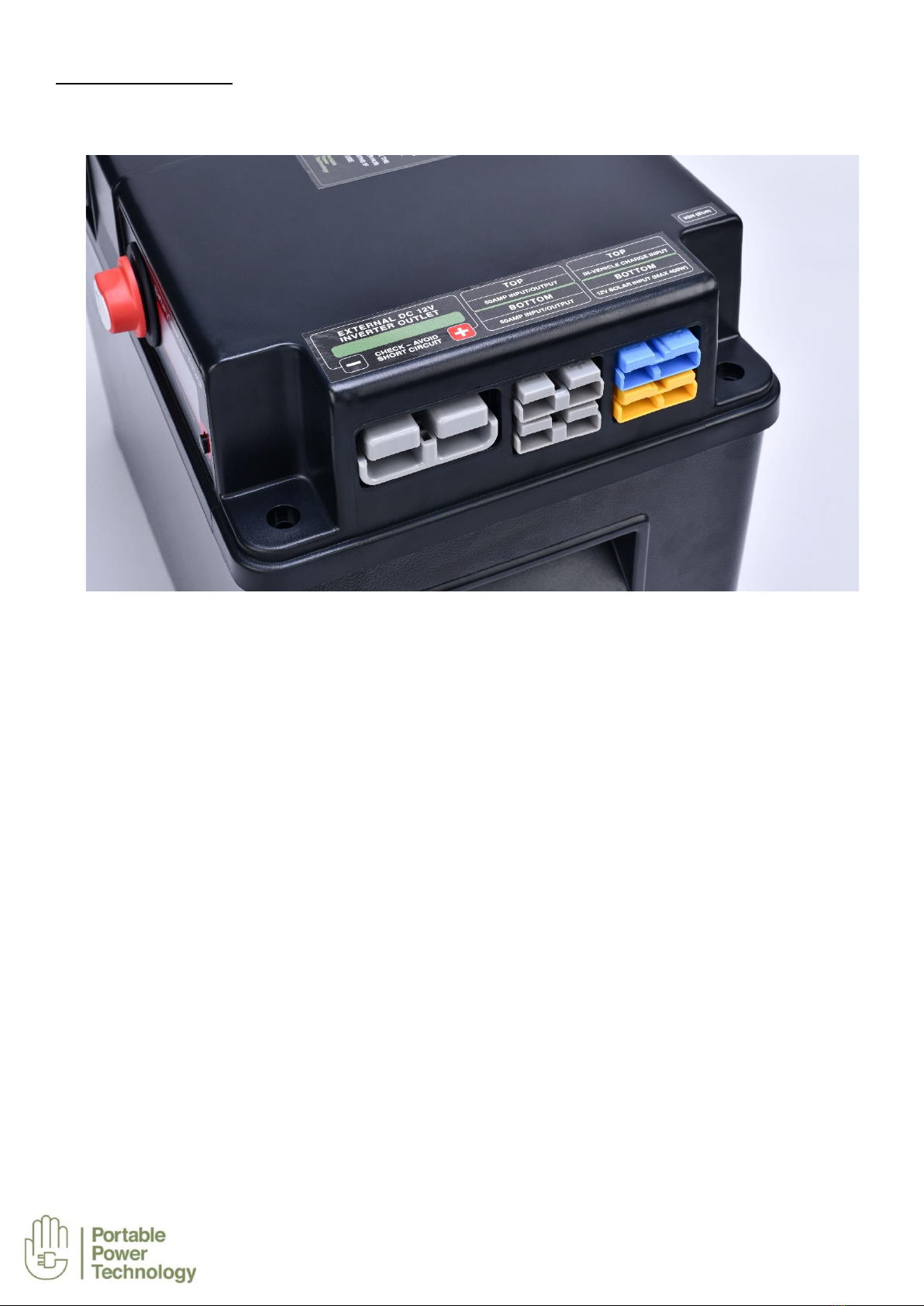
1. For compatibility with variable voltage alternators (EU6) a connection MUST be made to
the IGN labelled port using the supplied cable and connector. This wire should be
terminated to the ignition on the vehicle – if it is not connected the battery to battery
charger will revert back to conventional alternator program resulting in reduced charging.
2. For compatibility with older conventional alternators the IGN labelled port MUST NOT be
connected to ignition
3. Using the supplied input RED/BLACK cable connect the Anderson to the BLUE port
labelled “In Vehicle Charge Input”. The corresponding RED and BLACK other end have
ring terminals.
RED : to allow connection to an in line midi fuse (30A). The other side of the fuse will
require a DC cable terminated to the positive of the starter battery.
BLACK : requires connection to any common ground point (chassis) in the vehicle.

01474 761 051
www.portablepowertech.com
10
IMPORTANT NOTE : The black wire must be terminated to chassis for the in vehicle charging
to work.
NOTE : In vehicle charging from either alternator or solar is independent of the isolator
switch position – both the DC-DC charger and MPPT solar controller are directly connected
to the Vehicle Power Hub battery.
Charging from Solar
Vehicle Power Hub has an integrated MPPT solar charge controller making solar charging easy.
TIP : Solar will also top up and maintain the starter battery when the Hub battery is full
1. 30A MPPT Solar Charger built-in - ensure the max charging current from the solar panel or
array is not more than 30A, and open circuit voltage is not more than 25Vdc –therefore a 12V
solar panel only can be used (typically open circuit voltage would be around 20V to 23V)
2. Place the solar panel in direct sun
3. Using the supplied solar cable (Red/Black MC4 to Anderson) connect the solar panel with the
YELLOW port marked “12V SOLAR INPUT”

01474 761 051
www.portablepowertech.com
11
OPERATING INSTRUCTIONS
Using the Vehicle Power Hub
Once fully charged, the Vehicle Power Hub is ready to work immediately. No set up is required. All
outputs may be used simultaneously.
Installation
The Vehicle Power Hub comes complete with install kit for fast and easy deployment in vehicles.
The hub can be securely fastened using either of the supplied solutions:
➢Metal feet fixing kit –clamps bottom of the hub casing to the vehicle floor
➢Strapping kit –strap is looped around the case through the supplied hold down plates that
are secured to the vehicle floor
DC switch
All 12V sockets & Anderson plugs (except Blue and Yellow) are controlled by a DC isolator switch.
When isolator is OFF all inputs and outputs are disconnected from the Hub battery with the
exception of solar and in vehicle charging which remain independent of the isolator switch.
DC Operation –(Max 250A Total output BMS limited)
1. Please ensure the TOTAL discharging current is not more than 250A or else it may trigger
the main internal power breaker protection.
2. All connecting ports are high quality, but please plug in/disconnect properly for long service
life.
3. Max power of 12V DC socket is 120W each (12V 10A); max power of 50A Anderson plug is
600W (12V 50A); max power rating of larger Anderson plug is 2000W. Max power when
connected to inverter is 2000W for 30 mins and 1500W continuously. Please ensure
each port does not exceed the limit.
4. The maximum current between all 50A labelled input/output Anderson connector is 50A
TOTAL. Current higher than this will trip internal contactor that automatically resets when
the current is reduced.
5. Short circuit is forbidden. Any short circuit caused by improper use, will trigger breaker
protection or damage the Vehicle Power Hub. Failure by improper use will terminate
warranty. If in doubt or require service contact Portable Power Technology engineer.

01474 761 051
www.portablepowertech.com
12
CAUTION: If the external 225A power breaker protection is triggered, please turn off all loads
connected and turn the isolator switch to the off position. Then you can reset the breaker.
Should the problem persists contact Portable Power Technology (Or purchase distributor)
CAUTION: One 50A automatic reset breaker protects “50AMP INPUT/OUTPUT” outlets. Any over
discharge of “50AMP INPUT/OUTPUT‘’ outlets, please disconnect the load immediately,
reconnect in a few minutes and reduce total DC loads through these connectors to <50A
CAUTION: One internal 30A in-line fuse protect 12V DC sockets & dual USB socket. If power is
lost to these sockets please call Portable Power Technology before trying to open the case.
Power Inverter Connection
The Vehicle Power Hub is designed to allow connection of a 12VDC inverter to power 230V AC
loads. (inverter NOT supplied) –Max inverter power rating 2000W
Connection to the inverter is made via the larger Anderson connection labelled “External DC12V
Inverter Output”using the supplied inverter connection cable (1 metre 35mm² cable (red/black)
terminated with large Anderson connector and M8 ring terminals)
1. Turn off power hub using main isolator
2. Connect the correct red and black ring terminals to the corresponding + and –terminals on
the power inverter
3. Connect large Anderson to inverter output connector.
4. Turn on power hub using the main isolator
5. Connect load to the inverter output
6. Turn on inverter
CAUTION : Before connecting the inverter isolate the hub using the main DC isolator switch (OFF
position)
CAUTION : Maximum 250A discharge current is dependent on battery state of charge (SOC)
and temperature of unit –Refer to unit specification on page 15. Discharge from inverter
output is dependent on current and temperature. High discharge currents for more than 5
minutes might engage BMS over temperature protection. The unit will restart once unit has
cooled and on application of voltage source to any input (see below)
CAUTION : Maximum power inverter rating 2000W –If the maximum discharge of the
Battery Management System (BMS) of 250A continuous is exceeded then the BMS will go
into “Protection mode” and disconnect all loads. In order to reset the BMS a voltage source
of 12Vdc+ needs to be connected to any one of the input anderson connectors. Example
could be AC charger, Solar (if present), in vehicle charging with ignition on alternator on
08

01474 761 051
www.portablepowertech.com
13
MULTI FUNCTION DISPLAY
The Multi-function Display is designed to help the user to know the capacity of the battery inside the
power hub and easily estimate the amount of usable charge left in the battery.
1. Please turn the Battery Main Switch isolator to ON, to power the multi-function display
2. Please press “ON/OFF” button to check the Battery Capacity and Voltage.
Turning the Isolator switch to “OUT” allows the isolator switch to be removed to stop the Hub being
used.
NOTE : When the voltage of battery is 13.0 volt or above, BAT-Display is full, which doesn’t
mean the battery is charged 100% fully. Please charge the battery immediately, when BAT-
Display goes down to red sector, or the voltage is 11.0V or less.

01474 761 051
www.portablepowertech.com
14
TROUBLESHOOTING
If the Vehicle Power Hub fails to operate as specified, follow these troubleshooting steps below to
correct the issue.
Charging issues
1. Ensure DC isolator switch is turned “ON” (Not required for In vehicle or solar charging)
2. Please ensure all outlets and cords are connected securely.
3. Use watt meter kit to check the charging information (available on request)
4. AC charger - During AC charging, check the light of AC charger is Red and fan is working.
Check the fuse inside AC charger UK plug if no output
5. DC-DC in vehicle charger –Check connection AND black ground cable is connected to
vehicle chassis.
6. DC-DC in vehicle charger –Check IGN connection is made to vehicle ignition if using with
EU6 vehicle
7. MPPT Solar Charger –Check all connections from solar panel to “Solar input” connector
8. DC-DC in vehicle charger and MPPT Solar Charger - Under permission and instruction
from PPT remove the screws and open the lid, to inspect 40A inline fuse holder. Replace
40A fuse if needed with the same size fuse. Failure to request permission will result in
warranty being terminated.
12V and USB DC outlets issues
1. Ensure DC isolator switch is turned on
2. Ensure battery is charged and above 11V on the display
3. Check if the light on the USB socket is on or not
4. If BMS has gone into protection mode (over temperature or over current) then refer to
Caution note on page 12. Unit will require voltage source to reset. If over temperature reset
will only occur after unit has reduced in temperature
5. Seek permission and instruction from PPT, remove the screws and open the lid, to inspect
all breakers and the internal fuses
CAUTION: If above steps can’t correct the issue - Under permission and
Instruction ONLY of PPT, remove the screw and open the lid, checking main breaker and relative
wirings.
Call PPT on 01474 761051 for advice or permission BEFORE opening the unit

01474 761 051
www.portablepowertech.com
15
SPECIFICATIONS
Model Type
Vehicle Power Hub
1300
VPH1300
Vehicle Power Hub
2500
VPH2500
Vehicle Power Hub
3800
VPH3800
Battery Specification
Battery Type
LiFePO4 (Lithium Iron phosphate)
Battery Voltage (Nominal)
12.8V
Capacity
100Ah (1300Wh)
200Ah (2500Wh)
300Ah (3800Wh)
Max Charging Current
100 amps
Battery Lifespan
2000+ Life Cycles
BMS Capability (Max
discharge)
250A (BMS over current and over temperature limited) max
200A – continuous
Output Specification
DC Outlet
Dual 5V 2.1A USB
2X 12V 10A DC socket
2x 12V 50A connector (input/output)
1x External DC12V Inverter Outlet
Input Specification
AC Charger -230VAC
50Hz UK
Output 14.6V 40A
Output 14.6V 40A
Output 14.6V 40A
DCDC/MPPT Solar
Alternator input : 12-16VDC
Solar input : 12V-25VDC max 30A
LVD : 11.6V/12.8V
Output : 14.6V 30A
Operating Environment
Relative Humidity : 10% - 90%
Operating Temperature : -10 ℃ to +50 ℃
Dimension
455 (L) x 240 (D) x 330mm (H)
Net Weight
21.3Kg
27.0Kg
36.3Kg
Warranty
2 Years

01474 761 051
www.portablepowertech.com
16
IN THE BOX
The Vehicle Power Hub including:-
AC battery charger 40A with fused UK plug and terminated with Anderson connector x1
IGN cable (ignition): 3 metres and connector for smart alternator program (EU6 vehicles) x1
Inverter connection cable :1 metre 35mm² cable (red/black) terminated with large Anderson
connector, M8 ring terminals x1 and inline 225A circuit breaker
Starter battery connection cable for in vehicle charging: 1 metre 10mm² cable (red and black) –
Blue Anderson connector to M8 terminals to make in line fuse connection (40A recommended) and
ground connection with chassis x1
Solar cable : 1 metre 6mm² - MC4 to Yellow Anderson connector x1
Strapping/ Hold down kit containing fixing strap and 2 x hold down plates
Metal feet fixing kit containing 2 feet and 4 screws
Spare Anderson connectors x 5

01474 761 051
www.portablepowertech.com
17
MAINTENANCE
1. Keep your Vehicle Power Hub in a cool and dry place
2. Please fully recharge the Vehicle Power Hub every 3 months especially when not in use
3. Turn the main battery isolator to OFF when the Vehicle Hub is not in use
4. Check the lid bolts are tight every 6 months
5. Please make sure the Power Hub is securely mounted using the strap kit or feet fixing kit
when used inside a vehicle

01474 761 051
www.portablepowertech.com
18
WARRANTY
The Vehicle Power Hub is supplied with a 2 year warranty from the date of purchase against
defects in material and workmanship under normal use and service. Should your Vehicle Power
Hub prove defective within 2 years from the date of purchase, please contact us for a returns
number quoting the serial number and return the product, along with a copy of the proof of
purchase and an explanation of the fault.
We do not accept liability for any 3rd party damage however so caused.
Under this warranty we will replace or repair any parts found to be defective due to manufacturers
defect.
We are not responsible in any way for damages, losses, or inconvenience caused by equipment
failure or by user negligence, abuse, or use not accordance with the “User Manual” or any other
additional safety, use, or warnings included in the product materials.
Further, we are not liable for incidental, data loss, or consequential damages of any nature
resulting from the use of this product and any liability shall not exceed the purchase price of the
products.
In the event of a fault please contact the PPT Team on +44 (0)1474 761051
This manual suits for next models
5
Table of contents
Other Portable Power Technology Power Supply manuals
Popular Power Supply manuals by other brands

Delta Electronics
Delta Electronics Delphi NC Series Specification sheet

PumpSpy
PumpSpy BU-2000 Instructions and operating manual

TDK-Lambda
TDK-Lambda Z+ series user manual

Panasonic
Panasonic PK-A789S operating instructions

Altronix
Altronix AL600ULX Series installation guide

Pulsar
Pulsar POE042418B manual