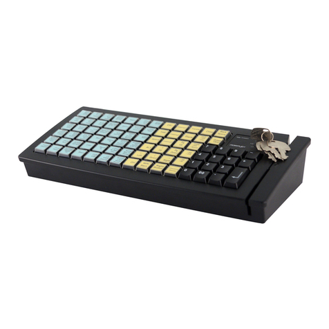
POSIFLEX KB2100 SERIES User manual

KB2100 SERIES
55 - PROGRAMMABLE
KEYBOARD
USER’S MANUAL
Rev. : C

NOTICE
The manufacturer of the POS keyboard makes no representations or
warranties, either expressed or implied, by or with respect to anything in this
manual, and shall not be liable for any implied warranties of fitness for a
particular purpose or for any indirect, special or consequential damages.
Information in this document is subject to change without notice and does not
represent a commitment on the part of the manufacturer.
FCC NOTICE
This equipment generates, uses, and radiate radio frequency energy. If not
installed and used in accordance with the user’s guide, may be cause
interference to radio communications. It has been tested and found to comply
with limits for a Class A digital device pursuant to subpart J of Part 15 of FCC
Rules, which are designed to provide reasonable protection against interference
when operated in a commercial environment. Operation of this equipment in a
residential area is likely to cause interference in which case the user at his own
expense will be required to take whatever measures may be required to correct
the interference.
i

TABLE OF CONTENTS
FEATURES . . . . . . . . . . . . . . . . . . . . . . . . . . . . . . . . . . . . . . . .
1
CONTENTS OF CARTON . . . . . . . . . . . . . . . . . . . . . . . . . . 2
CONNECTING THE KB2100 TO THE COMPUTER . . . . 3
FUNCTIONAL TEST . . . . . . . . . . . . . . . . . . . . . . . . . . . . . . . 4
PROGRAMMING THE KB2100 . . . . . . . . . . . . . . . . . . . . . . 6
COMMAND MENU . . . . . . . . . . . . . . . . . . . . . . . . . . . . . . . . .
8
ADVANCED PROGRAMMING . . . . . . . . . . . . . . . . . . . . . . 10
SPECIAL CONFIGURATION . . . . . . . . . . . . . . . . . . . . . . . 12
SPECIFICAITONS . . . . . . . . . . . . . . . . . . . . . . . . . . . . . . . . . 16
ii

FEATURES
Programs all computer keys including alphanumeric characters, Shift, Alt,
ESC, F1, etc.
Provides 55 programmable keys plus 1 programmable key-lock switch.
Does not require a TSR program and therefore avoids application software
crashes.
Does not require a battery. Holds data over 100 years.
Uses highly reliable, full-travel tactile keys.
Does not require an external programming kit.
Provides an optional built-in credit card reader and paper money clip.
Reads and writes up to 255 characters per key.
Provides true keyboard wedge function that operates with or without the
normal computer keyboard connected.
Provides optional output formats: Standard keyboard emulation and RS232.
Features an optional magnetic stripe reader:
-KB2100M2: Capable of reading tracks 1,2 and both tracks 1& 2.
-KB2100M3: Any combination of tracks 1,2, and 3.
-Built-in decoder and wedge interface.
Permits simple field programmability.
Supports down loading of an entire 55-key template into the internal non-
volatile memory in just 7 seconds.
Includes replaceable label sheet.
Built with spill-proof construction.
Includes cable, utility software, and accessories.
Provides multi-level programming which allows different character strings
to be defined to the same key.
Provides for a variable time delay in key programmed of up to 240 seconds.
Provides a true Cap Lock function independent of any other keyboard being
connected.
Optional soft dust cover.
KB2100 Series User’s Manual 1

CONTENTS OF CARTON
1. POS Keyboard.
2. Keyboard to Computer interface cable.
3. Utility software disk
4. Three legend label sheets.
5. User’s Guide.
6. Key clip.
KB2100 Series User’s Manual 2

CONNECTING THE KB2100 TO THE COMPUTER
J2
6 5
4
3
2
1
J5
5 4
3
2
1
J1
6
5
4
3
2
1
J6
9 8 7 6
5 4 3 2 1
To computer
Keyboard port
From other keyboards
A. Connecting the KB2100 to a IBM PC (XT, AT or CLONE) Computer:
KB2100 as a Stand-alone keyboard
1. Using the supplied interface cable, connect the KB2100 to the computer
keyboard port. Plug the 6-pin connector into the J2 port of the KB2100.
Plug the 5-pin connector into the computer keyboard port.
KB2100 and Computer keyboard together
1. The KB2100 and the standard computer keyboard can be attached to the
computer without a selection switch. To implement, connect the KB2100
to the computer as outlined above. Plug the standard computer keyboard
into J5 of the KB2100.
Note: KB2100 connectors J1 and J6 are not used.
B. Connecting the KB2100 to a PS/2 Computer
KB2100 as a stand-alone keyboard
1. Using the supplied interface cable connect the KB2100 to the computer
keyboard port. Connect the 6- pin plug to J2 of the KB2100. Insert a AT-
to-PS/2 adapter between the PS/2 computer keyboard port and the 5-pin
connector of the supplied cable.
Note: The AT-to-PS/2 adapter is not included with the KB2100.
KB2100 and Computer keyboard together
KB2100 Series User’s Manual 3

1. The KB2100 and the PS/2 computer keyboard can be attached to the
computer without a selection switch. To implement, connect the KB2100
to the computer as outlined above. Plug the PS/2 computer keyboard into
J1 of the KB2100.
Note: KB2100 connectors J5 and J6 are not used.
C. KB2100-R, and a Computer terminal:
1. Connect J6 of the Kb2100-R to a RS232 port of the computer terminal.
Note: J1, J2 and J5 are not used.
FUNCTIONAL TEST
To determine the proper working condition of the KB2100, a test key
pattern was preprogrammed into the keyboard memory. Page 5 shows this test
pattern. For a quick functional test follow the functional test procedure below:
1. Connect the KB2100 as shown in the section “Connecting the KB2100 to
the Computer”.
2. Turn on the computer.
3. At the DOS prompt press the upper left-hand key on the keyboard.
4. If the word “PRICE” appears on the screen, the KB2100 is working!
5. To check all 55 keys, press each individual key and compare the result
with the test pattern.
6. To check out the magnetic stripe reader:
Hold a credit card with the magnetic stripe at the bottom and facing the
arrow mark. Slide the card through the reader slot. Make sure the bottom
edge of the card continuously touches the bottom edge of the reader. The
recorded data from the credit card will appear on the monitor.
KB2100 Series User’s Manual 4

KB2100 Series User’s Manual 5

PROGRAMMING the KB2100
1. Make a copy of the KB2100 utility software:
-Insert the KB2100 utility software disk into either drive A or B
-Type install.
2. Type
KBM.EXE and press Enter
The computer screen displays the Posiflex programming keyboard utility
graphics screen. There are 55 keys plus 1 programmable key switch in the
key-layout map to be programmed. The location in the key-layout map are
coded from A1 to L3. The location code in the key-layout map ready to be
programmed will blink. The key-contents of the keys in the same column
with the key ready to be programmed will be displayed at the lower part of
the screen.
3. Use the arrow keys to move around the key-layout map to select a proper
key to program.
4. Press ALT+A to enter ASCII Code editing mode or directly type the
programming text. Press ALT+ A again or press Up or Down key to leave
editing mode of that key and move on for programming of another key
until all keys required are programmed. It is not necessary to program all
the keys for the KB2100 to function properly. The maximum number of
characters per key is 255 and the maximum number of characters for all 55
keys is 1856.
5. Programming locations A1 and B1 are associated with lock key switch.
Usually, the lock key is controlled by management level personnel to
override certain security check out procedures. If the lock key is turned
counter-clockwise to the L1 position, the KB2100 outputs the security
code stored in A1. This acts the same as if a single push-button key is
depressed. Similarly, if the lock key is turned clockwise to the L2 position,
the KB2100 outputs the security code stored in B1.
6. Type ALT+ W to write the programmed data into the KB2100’s non-
volatile memory. It takes about 7 seconds complete the writing process.
7. Press F10 followed by Y to terminate the utility program.
8. To verify if the program was stored correctly, press any programmed key
to display its contents on the monitor.
9. After all the keys are programmed, identify each key with a precut label.
KB2100 Series User’s Manual 6
Remove the transparent key cap with the key clip. Place and center the
label on the key top. To reinstall the transparent key cap, just snap it onto
the key top.
10. For direct transfer between a template file and the KB2100, there is a
shortcut program named RWM.EXE.
The command RWM filename.tpl transfers from file in hard disk to data
in the KB2100 non-volatile memory, and the command RWM
filename.tpl –R transfers from data in the KB2100 non-volatile memory
to file on the hard disk.
KB2100 Series User’s Manual 7

COMMAND MENU
EXIT the program: ALT-X or ESC or F10
Enter the ASSCII-CODE editing mode: ALT-A or F5
Enter the SCAN-CODE editing mode: ALT-N or F8
* Change to the PREVIOUS keyboard page: PgUp
* Change to the NEXT keyboard page: PgDn
* Toggle to the different view mode: ALT-T
READ key definitions from the keyboard: ALT-R
WRITE key definitions to the keyboard: ALT-W
LOAD key definitions from a disk file: ALT-L or ALT-O
SAVE key definitions from a disk file: ALT-S
Delete contents of a key to the buffer: DEL
COPY contents of a key to the buffer: ALT-C
PASTE contents of a key from the buffer: ALT-P
UNDO the change made to a key: ALT-U
Input a MULTI-LEVEL SHIET mark: ALT-M
Change the keyboard CONFIGURATIONS: ALT-G or F3
Note: The commands marked with “*” do not apply to model KB2100 series.
W
R
L
S
HDRD DISK KB-2100
RAM
The KB2100 keyboard, working in conjunction with KBM.EXE utility software,
can perform the following powerful function:
Program up to 55 keys and save the results as a template. The template can
then be stored (S) on the hard disk or written (W) into the non-volatile
KB2100 Series User’s Manual 8

memory of the KB2100. The number of templates that can be stored is
only limited by the size of the disk hard disk.
Load (L) a pre-programmed template from the hard disk into the
computer’s volatile RAM memory. The same template can then be written
(W) into the non-volatile memory of the KB2100. This process, as an
example, allows a restaurant to change a breakfast menu to a lunch menu
in just seven seconds.
Read (R) a working KB2100 template into the computer’s volatile RAM
memory.
The template can then be saved (S) to the hard disk for future use.
KB2100 Series User’s Manual 9

ADVANCED PROGRAMING-Special function keys
The KB2100 POS keyboard supports special control and function keys
such as the Shift, Ctrl, Alt, F1 through F12, and the up/down/left/right arrow
keys as well as alphanumeric characters. The procedure to program these special
keys is as follows:
1. Start the KBM.EXE utility program.
2. Select the key to be programmed with the alphanumeric or special
function. Press ALT+ N or F8 to enter the scan code mode. Enter the
programming characters. In the scan code mode each alphanumeric
character is inside parenthesis ( ). To program special function or control
keys press ESC first, followed by the special function or control key. For
example, to program the Ins key press ESC and then the Ins key. To
program the ESC key, press ESC twice. See special notes below.
3. When use of any of ALT, CTRL or SHIFT in a programmed key causes
any trouble in the application, please program a release code of the above
three keys in proper sequence to get smooth operation. Procedure is as the
following:
For example to program the ALT- Dkey.
1). Press F8 to Enter scan – code mode.
2). Press ESC ALT D.
3). Press ESC F ESC ALT. (to release the ALT key)
4).“ALT (D) 0F0 ALT” will be displayed on monitor.
5). In this case, 0F0 is the release code.
Notes:
I. Special function and control keys may require a leading ESC code. A
simple rule to follow is that if a character can not be entered directly,
then add a leading ESC code first.
II. For any key programmed under the scan code mode, pressing ALT + A
or F5 for ASCII code mode will alter the content to some
unrecognizable codes. Pressing ALT + N or F8 to enter scan code mode
will rescue the situation, and vice versa.
KB2100 Series User’s Manual 10

ADVANCED PROGRAMMING-Special features
To program special time delays
1. Start the KBM.EXE utility program.
2. Select the key where the time delay is to be used.
3. Enter any character(s) before the delay position. Depress ALT and D
together. Enter the delay (in seconds) and press Enter. The delay can be
up to 240 seconds.
To program multi-level definition
1. Start the KBM.EXE utility program.
2. Select the key which will have the multi-level function.
Note: Each key can be programmed to as many levels as needed (up to
255 characters per key).
3. Program the first level of information into the key then press ALT and S
together. A separator mark will be displayed after the last character.
Program the second level information after this separator bar. Continue
adding separator and new level up to the level required.
4. There must be another key programmed as the change Level key. for the
multi-level programmed key to works. Select an empty key to be used as
the change Level key, Press ALT and M together to put a level marker
<m> to the content of the key, To put two level markers <m> <m> to the
change Level Key, just press ALT and Mtogether twice Any Change
Level Key Programmed with more than 7 level markers will be regarded
as with only 7 level markers. There shall be no other information in the
content of any Change Level Key.
5. To utilize the multi-level programmed key. Press the multi-level
programmed key itself without pressing any Change Level Key, only the
information of the first level will come out. Press the Change Level Key
with one level marker together with a multi-level programmed key, only
the information of second level of that multi-level programmed key will
come out, and so on.
6. Pressing the Change Level Key with one marker and the Change Level
Key with two marker and the multi-level programmed key together will
KB2100 Series User’s Manual 11

work as if pressing a Change Level Key with three markers and the multi-
level programmed key together. The fourth level of the multi-level
programmed key will come out in either methods above. Through such
approach, one can utilize a multi-level programmed key with more than
eight levels program. (Pressing a Change Level Key with seven markers
and a Change Level Key with one marker together with the multi-level
programmed key will give the ninth level) However be as such usage of
too many levels could confusing, this approach is not recommended.
To program a Cap Lock key
This features adds a true Cap Lock function to the keypad.
1. Start the KBM.EXE utility program.
2. Select the key which will become the Cap Lock key. Press ALT + A to
enter the ASCII code mode.
3. Press ALT and Ctogether.
SPECIAL CONFIGURATION
Special configuration is accessed through F3 for the configuration menu. The
following options are available:
a. Send Break-Codes for Scan-Code: YES
b. Beep while a key is pressed: YES
c. Beep if a key is undefined: NO
f. Use ALT + num to generate ASCII codes: YES
j/k. Change InterCharacter Delay (ms): 4
l. Enable RS232 output: NO
(m. Baud Rate: 9600)
(n. Parity: NONE)
(o. Data bits:8)
Press ESC to return, or the first letter to change the setting.
In the configuration screen, pressing the correspondent letter of the
“YES” “NO” settings will toggle the setting. Pressing the “J” key each time will
KB2100 Series User’s Manual 12

increase the intercharacter delay by one millisecond. Pressing the “k” key each
time will decrease the intercharacter delay by one millisecond. The commands
“m” through “o” will show up only when item “1” is set to “YES” As the default
for item “1” is “NO” these three lines will in fact not be there. This item “1” for
RS232 output is only applicable for KB2100R. Pressing the “ESC” key will
change the screen back to the view mode screen.
Here are the explanations for the detail contents in the configuration list.
a. Send Break-Code for Scan-Codes: When this item is set to “YES”,
the programmable keyboard sends break-codes at the end of each
Scan-Code edited key to release all special key presses engaged in
the Scan-Code edited key. When this item is set to “NO”, the
programmable keyboard does not send break-code automatically. So
that, unless there is any release code programmed, the “SHIFT”,
“CRTL’, “ALT” key if programmed in a Scan-Code edited key will
remain pressed at the end of that Scan-Code edited key. The default
of this item is “YES”.
b. Beep while a key pressed: When this item is set to “YES”, the
programmable keyboard is enabled to deliver a beeping sound for
the key-press operation. When this item is set to “NO”, the
programmable keyboard works in a silent mode, and will not deliver
any beeping sound at the key-press. The default of this item is
“YES”.
c. Beep if a key is undefined: This item works only when the previous
item is set to “YES”. When this item is set to “YES” and when the
key pressed it not defined (programmed), the programmable
keyboard beeps. This sound is the same as the sound for the defined
key, and is governed by the silent mode of previous item. When this
item is set to “NO”, the programmable keyboard will not beep at the
key press of an undefined key. The default of this item is “NO”.
KB2100 Series User’s Manual 13

f. Use ALT + num to generate ASCII codes: When this item is set to
“YES”, the programmable keyboard transforms the ASCII codes for
the key presses of the ASCII-code edited key according to their
meanings instead of their locations. This function is very important
to some keyboards which have different layouts from the US
keyboard such as the European keyboards to operate correctly.
However this alternative consumes time and makes the
programmable keyboard to perform a little bit slower. When this
item is set to “NO”, the programmable keyboard delivers the ASCII
codes for the key presses just according to their locations which is
very suitable for the US keyboard. The default of this item is “YES”.
The user of US systems may change this item to “NO” to improve
the performance.
J/k. Change interCharacter Delay (ms): When a character string of more
than one character is programmed in one key of the programmable
keyboard, the speed of delivering the characters when the key is
pressed is adjustable to match the system requirement. The time
delay in transmitting two adjacent characters defined in a
programmed key when that key is pressed is hereby defined as
interchatacter delay and is adjustable between 0 and 140
milliseconds. Press “j” to increase or press “k” to decrease by one
millisecond each time till suitable delay time is reached. The default
value for this items is set to “4”.
l. Enable RS232 Output: This item is used in model KB2100R only.
When this item is set to “YES”, the programmable keyboard delivers
its output through the RS232 port (J6 of KB2100R). Please note that
when using RS232 output the keyboard must be supplied with an
external power source and J1, J2, J5 should be disconnected. When
this item it set to “NO”, the programmable keyboard disables the
RS232 port. The default of this item is “NO”
m. Baud Rate: This item is used in model KB2100R only and will show
up and be effective only when the RS232 output is enabled (item “l.”
set to “YES”). The default value of this item is set at 9600, pressing
“m” key once can change the baud rate of the programmable
KB2100 Series User’s Manual 14

keyboard to 19200, next press will make it to 2400, one more press
changes it to 4800, another one more press will change the baud rate
to 9600 again.
n. Parity: This item is used in model KB2100R only and will show up
and be effective only when the RS232 output is enabled (item “l.” set
to “YES”). The default value for this item is “NONE”, which means
that in the RS232 communication protocol no parity bit is used.
Pressing “n” key once the choice will become “EVEN”, which
means that one bit is engaged for even parity check. Further press of
“n” key will change this item to “ODD”, which means that one bit is
engaged for odd parity check. One more press of “n” key will return
the choice to “NONE” again
o. Data bits: This item is also used in model KB2100R only and will
show up and be effective only when the RS232 output is enabled
(item “l.” set to “YES”). The default value for this item is “8”, which
means that in the RS232 communication protocol there are 8 bits to
form a data byte. Pressing of “o” key will toggle the choice between
“8 and “7” which means only 7 bits are used to represent the data.
KB2100 Series User’s Manual 15

SPECIFICATIONS
MECHANICAL:
Weight……………..………………………..1.6kgs or 3.6lbs
Dimension in mm (inches)………………….354 x 158.5 x 37 mm
13.94” x 6.24” x 1.46”
(W x D x H)
ENVIRONMENTAL:
Operating temperature………. 0 to + 50ºC or 32 to 122 ºF
Storage temperature……….-20 to + 70ºC or – 4 to 168ºF
Relative humidity………….90%, non-condensing
Vibration…………………..4G
Shock………………………40G
ELECTRICAL:
Voltage………………………..5VDC± 10%
Current………………………..25 ma
50 ma (Models KB2100M2, M3, R)
MAGNETIC STRIPE READER (Models KB2100M2, M3):
Tracks………………………..1, 2, and 3
Card feed speed………………4 to 47 inches/second
Card feed force……………….6 oz, typical
Head life………………………300,000 passes minimum
KB2100 Series User’s Manual 16

Connector Pin Function
5
J1
3
Model KB2100: J1-1 Keyboard data 6
J1-2 NC 1
4
J1-3 Ground 2
J1-4 +5VDC J2
J1-5 Clock
6 5
4
3
2
1
J2-1 Clock
J2-2 Keyboard data
J2-3 NC
J2-4 Ground J5
J2-5 +5VDC
5 4
2
1
3
J5-1 Clock
J5-2 Keyboard
J5-3 NC J6
J5-4 Ground 5 4 3 2 1
J5-5 +5VDC
Model KB2100-R: J6-1, 4, 6 DCD, DTR, DSR 8
9 7 6
J6-2 Jumper selectable as output
J6-3 Jumper selectable as output
J6-5 Ground
J6-7, 8 RTS, CTS
J6-9 +5VDC
KB2100 Series User’s Manual 17
Table of contents
Other POSIFLEX Keyboard manuals

POSIFLEX
POSIFLEX KB-6800 Series User manual

POSIFLEX
POSIFLEX KB-6600 Series User manual

POSIFLEX
POSIFLEX KB3100 User manual

POSIFLEX
POSIFLEX KB6000 SERIES User manual

POSIFLEX
POSIFLEX KB3100 User manual

POSIFLEX
POSIFLEX KB-6600 Series User manual

POSIFLEX
POSIFLEX PST KB136 Series User manual

POSIFLEX
POSIFLEX KB-6600 Series User manual

POSIFLEX
POSIFLEX KB3200 Series User manual