POSIFLEX PST KB136 Series User manual

TM
PST KB136 SERIES
QWERTY KEYBOARD

TM

i
TM
TABLE OF CONTENTS
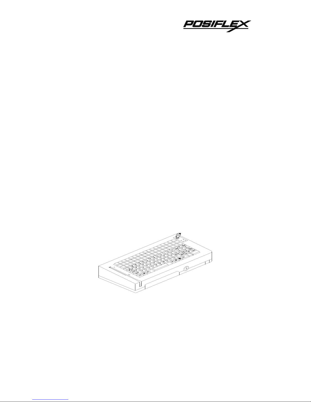
OVERVIEW . . . . . . . . . . . . . . . . . . . . . . . . . . . . . . . . . . . . . . . . . . . . . . . 1 - 1
SCOPE . . . . . . . . . . . . . . . . . . . . . . . . . . . . . . . . . . . . . . . . . . . . . . 1 - 1
FEATURES . . . . . . . . . . . . . . . . . . . . . . . . . . . . . . . . . . . . . . . . . . . 1 - 1
MODEL NUMBERS . . . . . . . . . . . . . . . . . . . . . . . . . . . . . . . . . . . . 1 - 2
ACCESSORIES . . . . . . . . . . . . . . . . . . . . . . . . . . . . . . . . . . . . . . . 1 - 2
OPTIONS . . . . . . . . . . ..................................1 - 2
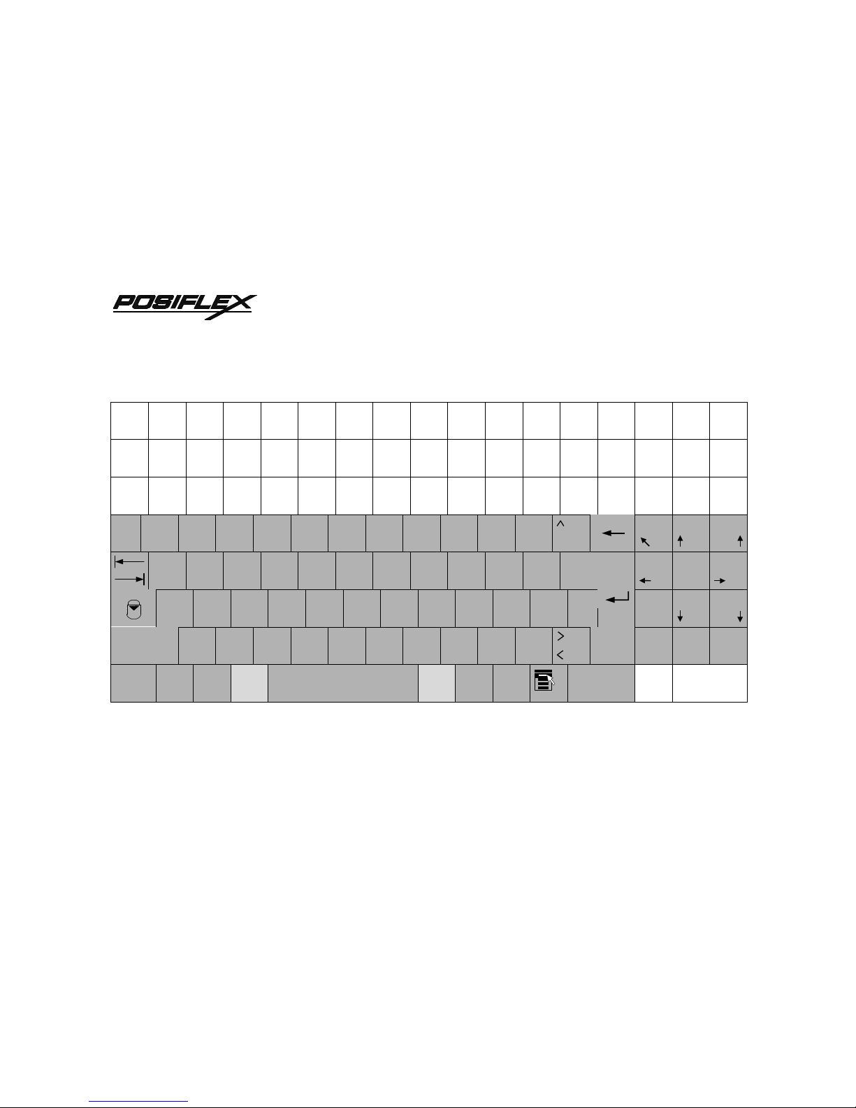
STANDARD LAYOUT . . . . . . . . . . . . . . . . . . . . . . . . . . . . . . . . . . . . 2 - 1
FRANCE . . . . . . . . . . . . . . . . . . . . . . . . . . . . . . . . . . . . . . . . . . . . . 2 - 2
GERMANY . . . . . . . . . . . . . . . . . . . . . . . . . . . . . . . . . . . . . . . . . . . 2 - 3
ITALY . . . . . . . . . . . . . . . . . . . . . . . . . . . . . . . . . . . . . . . . . . . . . . . . 2 - 4
NETHERLANDS . . . . . . . . . . . . . . . . . . . . . . . . . . . . . . . . . . . . . . 2 - 5
PORTUGAL . . . . . . . . . . . . . . . . . . . . . . . . . . . . . . . . . . . . . . . . . . 2 - 6
SPAIN . . . . . . . . . . . . . . . . . . . . . . . . . . . . . . . . . . . . . . . . . . . . . . . 2 - 7
SWEDEN/FINLAND . . . . . . . . . . . . . . . . . . . . . . . . . . . . . . . . . . . 2 - 8
UNITED KINGDOM . . . . . . . . . . . . . . . . . . . . . . . . . . . . . . . . . . . . 2 - 9
UNITED STATES . . . . . . . . . . . . . . . . . . . . . . . . . . . . . . . . . . . . . 2 - 10
INSTALLATION . . . . . . . . . . . . . . . . . . . . . . . . . . . . . . . . . . . . . . . . . . 3 - 1
HARDWARE INSTALLATION . . . . . . . . . . . . . . . . . . . . . . . . . . 3 - 1
UTILITY INSTALLATION . . . . . . . . . . . . . . . . . . . . . . . . . . . . . . . 3 - 2
PROGRAMMING . . . . . . . . . . . . . . . . . . . . . . . . . . . . . . . . . . . . . . . . . 4 - 1
HOT KEY PROGRAMMING . . . . . . . . . . . . . . . . . . . . . . . . . . . . 4 - 1
PREPARATION . . . . . . . . . . . . . . . . . . . . . . . . . . . . . . . . . 4 - 1
ENTER “HOT KEY PROGRAMMING” MODE . . . . . . . 4 - 1
INPUT THE CONTENT TO BE PROGRAMMED . . . . . 4 - 2
EXIT “HOT KEY PROGRAMMING” MODE . . . . . . . . . . 4 - 3
PROGRAMMING UTILITY (KBM.EXE) . . . . . . . . . . . . . . . . . . . 4 - 4
GENERAL . . . . . . . . . . . . . . . . . . . . . . . . . . . . . . . . . . . . . . 4 - 4

ii
TM
COMMAND LISTING IN VIEW MODE . . . . . . . . . . . . . . 4 - 6
COMMAND LISTING IN ASCII-CODE EDITING MODE . . . . . .
. . . . . . . . . . . . . . . . . . . . . . . . . . . . . . . . . . . . . . . . . . . . . . . . 4 - 7
COMMAND LISTING IN SCAN CODE EDITING MODE . . . . . .
. . . . . . . . . . . . . . . . . . . . . . . . . . . . . . . . . . . . . . . . . . . . . . . . 4 - 8
ANSWER BACK CODE . . . . . . . . . . . . . . . . . . . . . . . . . . 4 - 9
HARDWARE LIMITATION . . . . . . . . . . . . . . . . . . . . . . . . 4 - 9
SHORTCUT UTILITY (RWM.EXE) . . . . . . . . . . . . . . . . . . . . . . . 4 - 10
DETAILS IN PROGRAMMING . . . . . . . . . . . . . . . . . . . . . . . . . . . 5 - 1
APPLICATION . . . . . . . . . . . . . . . . . . . . . . . . . . . . . . . . . . . . . . . . . . . 6 - 1
KEYBOARD CONSTRUCTION . . . . . . . . . . . . . . . . . . . . . . . . . 6 - 1
LED’S . . . . . . . . . . . . . . . . . . . . . . . . . . . . . . . . . . . . . . . . . . . . . . . 6 - 1
6 POSITION KEY - LOCK . . . . . . . . . . . . . . . . . . . . . . . . . . . . . . 6 - 2
PUSH KEY SWITCH MATRIX . . . . . . . . . . . . . . . . . . . . . . . . . . . 6 - 3
KEY TOP REPLACEMENT . . . . . . . . . . . . . . . . . . . . . . . . . . . . . 6 - 3
MAGNETIC STRIPE READER SLOT . . . . . . . . . . . . . . . . . . . . 6 - 6
PRELOADED PATTERN . . . . . . . . . . . . . . . . . . . . . . . . . . . . . . . 6 - 7
HARDWARE DETAILS . . . . . . . . . . . . . . . . . . . . . . . . . . . . . . . . . . . 7 - 1
PCB LAYOUT . . . . . . . . . . . . . . . . . . . . . . . . . . . . . . . . . . . . . . . . 7 - 1
CONNECTORS . . . . . . . . . . . . . . . . . . . . . . . . . . . . . . . . . 7 - 1
JUMPER SETTING . . . . . . . . . . . . . . . . . . . . . . . . . . . . . . 7 - 2
PART NUMBERS . . . . . . . . . . . . . . . . . . . . . . . . . . . . . . . . . . . . . . . . 8 - 1

1 - 1
TM
OVERVIEW
SCOPE
The KB136 unit is the optional programmable keyboard segment within the
PST systems replacing the original KB112. This keyboard provides in the lower part a
“QWERTY” keyboard that resembles the standard PC keyboard and at the top a
matrix of 3 by 17 locations for freely programming purpose. Nevertheless, there are 2
more programmable keys within the “QWERTY” region. The “QWERTY” region is
available for layout of various countries.
This printed material works as a supplement to the available documentation
for the PST systems. In other words, the User’s Manual and Technical Manual of the
relevant PST system should be referred to for proper comprehension of the KB136.
Should there be any further question, please visit our web site
(http://www.posiflex.com.tw) and look for the “KB136 Technical Guide”.
FEATURES
lBase structure in 8 by 17 matrix
lLower 5 rows of the matrix provide “QWERTY” keyboard, numerical keypad and
2 programmable keys for each country
lUpper 3 rows of the matrix provide powerful programmable ability (programming
under Windows, multiple page, multiple level, whole range key content, time
delay, position sense answer back code, etc.)
lA 6 position control key to provide security lock, multiple page controller and
answer back code control
lTotal memory for keys to be programmed: 8 KB
lSpill-proof construction
lWear resistant Laser marked QWERTY and numeric keys
lReliable and pleasant key click
lExtension keyboard connector
lComfortable key size
lAlternative double key

1 - 2
TM
MODEL NUMBERS
MODEL NUMBER COUNTRY / LANGUAGE
PSTKBQRTY-FR French
PSTKBQRTY-GR Germany
PSTKBQRTY-IT Italy
PSTKBQRTY-NL Netherlands
PSTKBQRTY-PO Portugal
PSTKBQRTY-SP Spain
PSTKBQRTY-SV Sweden / Finland
PSTKBQRTY-UK United Kingdom
PSTKBQRTY-US United States
ACCESSORIES
When the KB136 QWERTY keyboard is supplied with a PST system, the
original 112 key programmable keyboard is replaced by the KB136 QWERTY
keyboard. Meanwhile, all the keyboard relevant accessories of the original 112 key
programmable keyboard are deleted from the PST accessories carton. These parts
include: Legend sheet in 4 colors; Key clip (1 pc of QC-2000), Single key transparent
key cap (92 pcs); Double key transparent key cap (2 pcs); Quad key transparent key
cap (1 pc) and Blank key (2 or 4 pcs). The following accessories for the QWERTY
keyboard are placed in the PST accessories carton instead: This manual (1 copy);
Legend sheet for QWERTY keyboard in 4 colors (CLABKBPSTHKB112); Key clip
(1 pc of QCH-2000), Single key transparent key cap (52 pcs) and Double key
transparent key cap (1 pc).
OPTIONS
lSingle key
lDouble key
l2 tracks ISO MSR
l3 tracks ISO MSR
lJIS I/II MSR

2 - 1
TM
STANDARD LAYOUTS
lFRANCE
lGERMANY
lITALY
lNETHERLANDS
lPORTUGAL
lSPAIN
lSWEDEN/FINLAND
lUNITED KINGDOM
lUNITED STATES

2 - 2
TM
FRANCE
1234567890°+789
²&é" # ' { ( [
- ¦ è `_
\çà
@
) ] = }
AZERTYUI O P£ 4 5 6
$
QSDFGHJKLM%µ123
ù*
Entrée
Fin
WXCVBN?./§ 0 00 .
ñ
, ; : !ñInser Suppr
Ctrl ÿAlt Alt Gr ÿCtrl

2 - 3
TM
GERMANY
°!"§$%&/()=?`789
12 ² 3 ³ 45 6 7 { 8 [ 9 ] 0 } β\ ´Pos1 Bild
QWERTZUI O PU*456
@+
ASDFGHJKLOA'123
ò#Ende Bild
YXCVBNM;:_ 0 00 ,
ñµ, . -¦ ñEinfg Entf
Strg ÿÿ Alt Alt Gr ÿÿ Strg

2 - 4
TM
ITALY
¦!"£$%&/()=? 7 8 9
\12345 6 7 8 9 0 'ìPag
QWERTYUI O Pé*456
è [ + ]
ASDFGHJKLç°§ 1 2 3
ò @à # ù
Invio
Fine Pag
ZXCVBNM;:_ 0 00 .
ñ, . -ñIns Canc
Ctrl ÿÿ Alt Alt Gr ÿÿ Ctrl

2 - 5
TM
NETHERLANDS
§!"#$%&_()'? 7 8 9
@¬ 1 ¹ 2 ² 3 ³ 4 ¼ 5 ½ 6 ¾ 7 £ 8 { 9 } 0/ \ ° ¸Home PgUp
QWERTYUI O P¦456
¶ *
ASDFGHJKL±`123
Caps
Lock ß +´End PgDn
ZXCVBNM;:=[0 00 ,
ñ« » ¢ µ,. · -] ¦ ñIns Del
Ctrl ÿÿ Alt Alt Gr ÿÿ Ctrl

2 - 6
TM
PORTUGAL
¦!"#$%&/()=?» 789
\12 @3 £ 4 § 5 6 7 { 8 [ 9 ] 0 } '«Home PgUp
QWERTYUI O P*`456
+´
ASDFGHJKLǪ123
Caps
Lock ºEnd PgDn
ZXCVBNM;:_ 0 00 .
ñ, . -ñIns Del
Ctrl ÿÿ Alt Alt Gr ÿÿ Ctrl

2 - 7
TM
SPAIN
ª!"·$%&/()=?¿789
º\ 1 ¦ 2 @3 # 456 ¬ 7 8 9 0 '¡Inicio RePág
QWERTYUI O P*456
` [ + ]
ASDFGHJKLÑ Ç 123
Bloq
Mayús ´ { } Fin AvPág
ZXCVBNM;:_ 0 00 .
ñ, . -ñIns Supr
Ctrl ÿÿ Alt Alt Gr ÿÿ Ctrl

2 - 8
TM
SWEDEN/FINLAND
½!"#%&/()=?`789
§ 1 2 @ 3 £ 4 $ 5 6 7 { 8 [ 9 ] 0 } + \ ´Home PgUp
QWERTYUI O PÅ456
ASDFGHJKLOA*123
Caps
Lock 'End PgDn
ZXCVBNM;:_ 0 00 ,
ñ, . -¦ ñIns Del
Ctrl ÿÿ Alt Alt Gr ÿÿ Ctrl

2 - 9
TM
UNITED KINGDOM
¬!"£$%&*()_+789
`12345 6 7 8 9 0 -=Home PgUp
QWERTYUI O P{ } 456
[ ]
ASDFGHJKL:@123
Caps
Lock ;'#End PgDn
ZXCVBNM?¦0 00 .
ñ
,./\ñIns Del
Ctrl ÿÿ Alt Alt Gr ÿÿ Ctrl

2 - 10
TM
UNITED STATES
!@#$%&*()_+789
`12 3 4 5 6 7 8 9 0 -=Home PgUp
QWERTYUI O P{}¦456
Tab []\
ASDFGHJKL:"123
Caps
Lock ;'Enter End PgDn
ZXCVBNM? 0 00 .
ñShift ,./ñShift Ins Del
Ctrl ÿÿ Alt Alt ÿÿ Ctrl

3 - 1
TM
INSTALLATION
HARDWARE INSTALLATION
To install KB136 into a PST system originally equipped with KB112, the user
should disassemble the KB112 from the PST system according to the instructions
given in the Technical Manual of respective PST system. After this disassembly, there
are three cables coming from the inside of the PST system, namely, a 2 pin cable for
the standby LED, a 4 pin cable for KB signal and a DIN 5 pin cable for the external
KB connector.
The user shall connect these three cables to the proper connectors in the
KB136 assembly as shown in the example below. Unlock the mechanical lock, place
the programmable keyboard down and back to the position, lock the mechanical lock
and screw on the 2 bottom screws as in reverse order of the disassembly of the
keyboard unit. The KB136 is then well installed.
Fig. 3 – 1 Cable connection
Cable for standby LED
4 pin cable for KB signal
External KB cable

3 - 2
TM
UTILITY INSTALLATION
There are in total three methods to program the programmable keys in KB136
QWERTY keyboard: “RWM.EXE” the straightforward direct read/write
programming utility; “KBM.EXE” the normal programming utility and the “Hot Key
Programming” most suitable to modify the key contents of one or two keys.
Installation procedures are required for utilities “KBM.EXE” and “RWM.EXE”.
In the utility diskette, there is a file named “INSTALL.EXE” for installation of
all the utilities into any operating system among Windows95 Windows 3.1 and DOS.
The user may install the programming utility by following the step by step
instructions from this executable program. The user may refer to the information on
our web site for a preview of this program.

4 - 1
TM
PROGRAMMING
HOT KEY PROGRAMMING
The KB136 programmable keyboard supports the “hot key programming”
method which is most useful in instant modification of a few keys in a
preprogrammed keyboard without entering the more sophisticated programming
utility. Of course, the user may also use this feature to program through out all 51
keys (3 rows, 17 columns) by 5 pages (LP and L1 to L4) at will. The whole process of
“hot key programming” contains 4 steps for each key to be programmed and is
illustrated as following:
PREPARATION
To enable “hot key programming” feature of the KB136 “QWERTY”
keyboard, a standard PC or PS-2 keyboard must be connected to the external KB
connector of KB136 before entering “hot key programming” mode. The user shall
then decide which key of which page is to be programmed and turn the 6 position
control key to the proper position before entering the “hot key programming” mode.
Please note that the answer back codes of the position control key and the 2
programmable keys in the numerical keypad are not covered by the “hot key
programming” feature.
ENTER “HOT KEY PROGRAMMING”
MODE
To enter the “hot key programming” mode, the user must input the “hot key”
and identify the key on the programmable keyboard to be programmed. The so-called
“hot key” is a special combination of keys pressed on the standard PC or PS-2
keyboard. In KB136, the “hot key” is defined as pressing and holding the left “Alt”
Preparation Enter “hot key
programming”
mode
Input the
content to be
programmed
Exit “hot key
programming”
mode

4 - 2
TM
key while pressing the “PRT SC” (“Print Screen”) key on the PC or PS-2 keyboard.
And by doing so, the KB136 will give 2 beeps to notify that it is ready to receive the
identification of which key to be programmed. Right after the “hot key” is released,
the user shall press the key to be programmed on the programmable keyboard once to
identify which key to be programmed. If the “hot key” is pressed for the second time
or the “esc” key is pressed prior to the press of the key on the programmable
keyboard, this mode will be aborted immediately. The user should not enter the “hot
key programming” mode when the programmable keyboard is already fully loaded
(no more free memory for further programming) by the key contents previously
programmed.
INPUT THE CONTENT TO BE
PROGRAMMED
Once the programmable keyboard enters the “hot key programming” mode
with the key to be programmed identified, what the user types on the standard PC or
PS-2 keyboard will be taken for the content to be programmed into that key of the
programmable keyboard till the user exits the “hot key programming” mode.
The legal input in this mode includes all alphabetical letters (including both
upper and lower cases), numerical digits (applicable only for keys at the area above
the alphabetical keys and excluding those on the numerical keypad), symbols (such as
`!”#$ and excluding those arithmetic signs in the numerical keypad) and the “enter”
key. The “shift” key, the “caps lock” key and the “back space” key are also accepted
in this mode to serve an editing purpose (for example, pressing “back space” will
erase the last character of the input instead of being treated as a character for input).
Pressing the “esc” key in this mode will abort the “hot key programming” mode
immediately. All the rest keys (such as the “Ctrl”, “Alt”, “Home”, any function key or
arrow key or any key in the numerical keypad) on the standard PC or PS-2 keyboard
are illegal inputs in this mode. The maximum number of key presses acceptable to any
key by “hot key programming” is 32.
All the input from the standard PC or PS-2 keyboard in this mode will also be
sent to the host computer. Any key press from the predefined or programmed KB136
for data input in “hot key programming” is prohibited.
This manual suits for next models
9
Table of contents
Other POSIFLEX Keyboard manuals

POSIFLEX
POSIFLEX KB-6800 Series User manual

POSIFLEX
POSIFLEX KB-6600 Series User manual

POSIFLEX
POSIFLEX KB-6600 Series User manual

POSIFLEX
POSIFLEX KB3200 Series User manual

POSIFLEX
POSIFLEX KB2100 SERIES User manual

POSIFLEX
POSIFLEX KB3100 User manual

POSIFLEX
POSIFLEX KB-6600 Series User manual

POSIFLEX
POSIFLEX KB3100 User manual

POSIFLEX
POSIFLEX KB6000 SERIES User manual