Positron BRX-XLR User manual

BRX-XLR User Guide 180-0145-001-R01
BRX-XLR
Broadband Reach Extender –Extra Long Reach
User Guide
March 2017

BRX-XLR User Guide 1 180-0145-001-R01
Publication Information
©2017 Positron Access Solutions Corporation. All rights reserved.
BRX-XLR
User Guide
Publication date: March 2017
Printed in Canada
Published By
Positron Access Solutions Corporation
5101 Buchan Street, Suite 220
Montreal, Quebec, Canada
H4P 2R9
Telephone US and Canada: 1-888-577-5254
International: +1-514-345-2220
Product names, other than Positron's, mentioned herein may be trademarks and/or registered
trademarks their respective owners.
Disclaimer Notice
Although Positron Access Solutions Corp. has made every effort to ensure the accuracy of the
information contained herein, this document is subject to change.

BRX-XLR User Guide 2 180-0145-001-R01
Regulatory Compliance and Safety
FCC Declaration of Conformance
The BRX-XLR models comply with part 15 class A of the FCC Rules. Operation is subject to the
following two conditions (1) This device may not cause harmful interference, and (2) this device must
accept any interference received, including interference that may cause undesired operation.
15 Class A Information
This equipment has been tested and found to comply with the limits for a Class A digital device,
pursuant to Part 15 of the FCC rules. These limits are designed to provide reasonable protection
against harmful interference when the equipment is operated in a commercial environment. This
equipment generates; uses and can radiate radio frequency energy and, if not installed and used in
accordance with the instruction manual, may cause harmful interference to radio communications.
Operation of this equipment in a residential area is likely to cause harmful interference in which case
the user will be required to correct the interference at his own expense.
In order to maintain compliance with FCC regulations shielded cables must be used with this
equipment. Operation with non-approved equipment or unshielded cables is likely to result in
interference to radio & television reception.
Industry Canada
The BRX-XLR models comply with ICES-003 of the Industry Canada Rules. Operation is subject to
the following two conditions: (1) This device may not cause harmful interference, and (2) this device
must accept any interference received, including interference that may cause undesired operation.
Les produits BRX-XLR sont conformes à la norme NMB-003 d'Industrie Canada. Leur fonctionnement
est sujet aux deux conditions suivantes: (1) le dispositif ne doit pas produire de brouillage
préjudiciable, et (2) ce dispositif doit accepter tout brouillage reçu, y compris un brouillage susceptible
de provoquer un fonctionnement indésirable.
Europe - EU Declaration of Conformity
The BRX-XLR models comply with the essential requirements of the EMC Directive 2014/30/EU and
Low Voltage Directive 2014/35/EU. The following test methods have been applied in order to prove
presumption of conformity with the essential requirements of the EMC Directive 2014/30/EU and Low
Voltage Directive 2014/35/EU:
CSA C22.2#60950-1: Issued: 2007/03/27 Ed: 2 (R2012) Information Technology Equipment Safety
Part 1: General Requirements; Amendment 1: 2011, Amendment 2: 2014
UL 60950-1: Issued: 2007/03/27 Ed: 2 Rev: 2014/10/14 Information Technology Equipment Safety
Part 1: General Requirements

BRX-XLR User Guide 3 180-0145-001-R01
IEC 60950-1: Issued: 2013/05/28 Ed: 2.2 Information Technology Equipment - Safety - Part 1:
General Requirements; Consolidated Edition. Ed. 2: 2005
IEC 60950-22 Issued: 2005/10/20 Ed: 1 Information Technology Equipment -Safety -Part 22:
Equipment to be Installed Outdoors
CSA 22.2 No. 60950-22-07 (R2016) Issued: 2007/04/23 Ed: 1 Information Technology Equipment -
Safety -Part 22: Equipment to be Installed Outdoors (Bi-National standard, with UL 60950-22)
UL 60950-22 Issued: 2007/04/23 Ed: 1 Information Technology Equipment -Safety -Part 22:
Equipment to be Installed Outdoors
EN 55022: 2010: Information technology equipment - Radio disturbance characteristics Limits and
methods of measurement
EN 55024: 2010: Information technology equipment - Immunity characteristics - Limits and methods of
Measurement
EN 55032: 2012: Electromagnetic compatibility of multimedia equipment - Emission Requirements
English
Hereby, Positron Access Solutions Corp. declares that the BRX-XLR models are in
compliance with the essential requirements and other relevant provisions of Directive
2014/30/EU and 2014/35/EU.
Français
Par la présente Positron Access Solutions Corp. déclare que les modèles BRX-XLR sont
conformes aux exigences essentielles et aux autres dispositions pertinentes selon les
normes 2014/30/EU and 2014/35/EU.
Safety
The BRX-XLR models conforms to IEC 60950-1/UL 60950-1/CSA C22.2 #60950-1 and IEC
60950-22/UL 60950-22/CSA C22.2 #60950-22 standards.
Les modèles BRX-XLR sont conformes aux normes IEC 60950-1/UL 60950-1/CAN C22.2
#60950-1 et IEC 60950-22/UL 60950-22/CAN C22.2 #60950-22.
Precautions and warnings
Always use a circuit that provides POTS sealing current to the copper pair to power the BRX-XLR
models. Never use power injector devices not approved by Positron Access Solutions for that use.
Using power injectors with voltage higher than 48V nominal may create risk of damaging the unit and
void its warranty.
There are no user-serviceable parts in the BRX-XLR-2. Do not attempt to open the unit. Doing so
may damage the seals and prevent the unit from meeting IP65. Rain water may leak into the unit and
damage its electronics leading into either its malfunction or its total failure. The modem should only
be opened by a technician trained and certified to service the product.
All wiring external to the product should follow the local wiring codes.

BRX-XLR User Guide 4 180-0145-001-R01
Be careful when splicing the BRX-XLR pairs to the twisted telephone cable pairs. Dangerous voltage
can be present on the pairs. Splicing should be done by a qualified person. Never splice pairs during
a lightning storm.
The equipment must be connected to a protective ground in accordance with the instructions provided
in this manual. Always ensure that BRX-XLR units are connected to a chassis ground path of 25 ohms
or less to avoid damage to the equipment from lightning strikes and other electrical surges.
Use of this product in a manner other than defined in this installation guide may cause damage to
equipment or injury to personnel.
All fuses on the unit are located in non-accessible areas and are not field serviceable. Please return
the unit to Positron Access Solutions for repair.
The BRX-XLR products are intended for installation in Restricted Access Locations only whether
installed indoor or outdoor.

BRX-XLR User Guide 5 180-0145-001-R01
Table of Contents
1General Description.........................................................................................................6
2BRX-XLR Main Advantages.............................................................................................6
3Bandwidth Performance and Placement Flexibility ......................................................6
3.1 Expected Bandwidth Improvement with BRX-XLR.............................................................6
3.2 Typical Increases in Customer Serving Area ....................................................................10
3.3 BRX-XLR Placement Flexibility..........................................................................................11
3.4 Optimum Placement............................................................................................................12
3.5 BRX-XLR Calculator............................................................................................................14
3.6 Miscellaneous Other Placement Guidelines .....................................................................14
4Technical Specifications................................................................................................16
5Packaging Information and Port Density .....................................................................17
6Installation and Operating Guidelines..........................................................................18
6.1 General Requirements for the Outside Plant (OSP)..........................................................18
6.2 POTS / Voice Lines..............................................................................................................19
6.3 Equipment Connection Diagram........................................................................................19
7Installation Procedure....................................................................................................20
7.1 Unpack.................................................................................................................................20
7.2 BRX-XLR 2-pair Standalone Unit Installation....................................................................21
7.3 Splicing Pairs ......................................................................................................................24
8How to Mitigate the Impact of Disturbers.....................................................................25
8.1 Grounding and Bonding.....................................................................................................25
8.2 Impulse Noise Protection ...................................................................................................27
9Troubleshooting Guidelines..........................................................................................28
10 Warranty and Customer Service...................................................................................34
11 Ordering Information .....................................................................................................35
Annex A.................................................................................................................................36
Annex B.................................................................................................................................39
Annex C.................................................................................................................................40

BRX-XLR User Guide 6 180-0145-001-R01
1 General Description
The Broadband Reach Extender –Extra Long Reach (BRX-XLR) is a fully integrated solution that
extends the reach of deployed ADSL / ADSL2+ DSLAMs or MSANs to deliver higher bandwidth
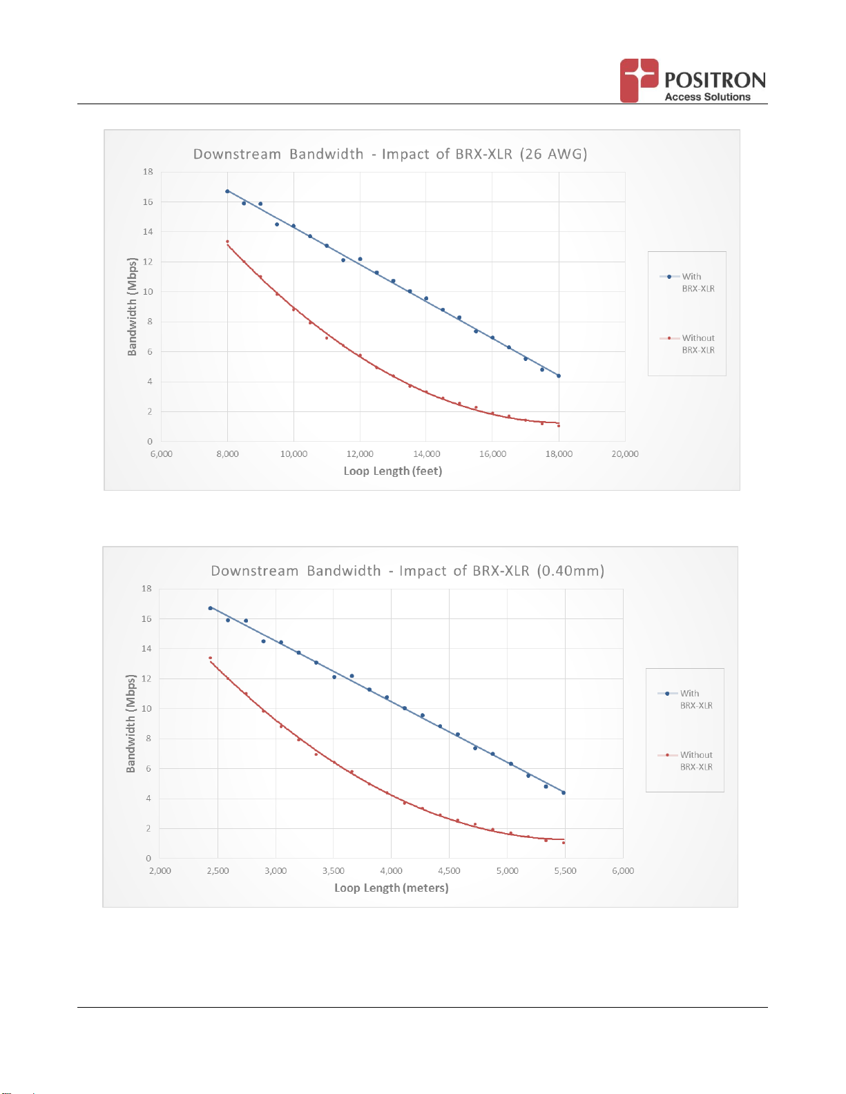
services to underserved or unserved markets. For example, it extends the reach of a 10 Mbps
downstream service from 9,100 feet (2.8km) to 12,500 feet (3.8 km) on 26 AWG / 0.40mm gauge
copper, an increase of almost 40%, and the same level of increase is achieved for larger size
cables. Furthermore, this 40% increase in reach results in an estimated 100% increase in CSA
(Customer Serving Area) since the area served is proportional to the square of the lineal distance.
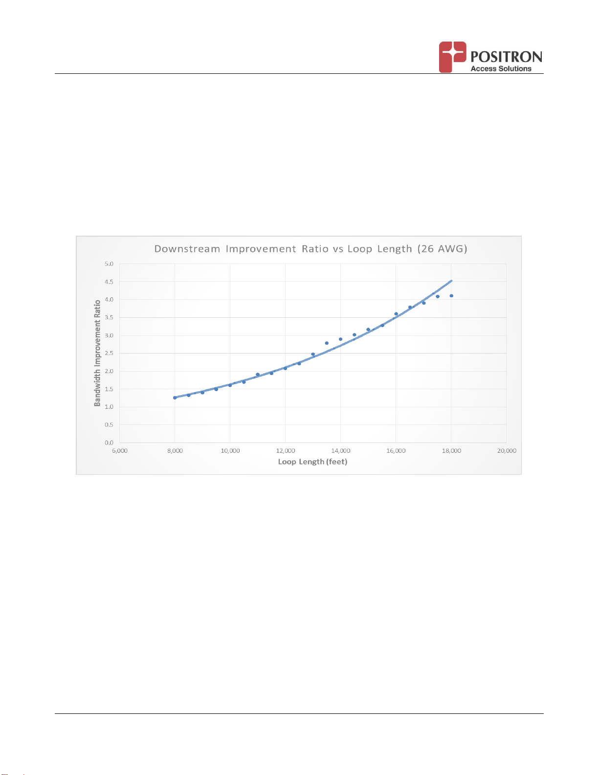
Another way to look at the benefits of this same function is that a client that is situated at 12,500
feet (3.8km) from the DSLAM, on a 26 AWG (0.40mm) copper pair will see the downstream
bandwidth increase from approximately 5Mbps to over 10Mbps. Over longer distances, the
bandwidth improvement ratio is between 2 and 5. It is important to note that these benefits are
obtained without the need to change the DSLAM/MSAN or the user CPE. By significantly
increasing the effective bandwidth and reach of existing xDSL lines, operators can deliver true
broadband speeds to each of their subscribers, even those located in remote areas or currently
located too far from the DSLAM to receive any service.
2 BRX-XLR Main Advantages
Extends up to 100% the ADSL/ADSL2/ADSL2+ Customer Serving Area (CSA).
Improve effective bandwidth typically by a ratio of 2 to 5 for ADSL/ADSL2/ADSL2+ loops.
No extra power required. The BRX-XLR uses less than 2mA from the -48V sealing
current of the POTS line.
Flexible Shelf design allows more subscribers to be added in the future.
Turnkey pedestal option available.
Auto calibration, no software to configure or dip switch.
Easy to install, deploy, and maintain.
3 Bandwidth Performance and Placement Flexibility
3.1 Expected Bandwidth Improvement with BRX-XLR
The BRX-XLR automatically adjusts itself to optimize performance. The BRX-XLR provides noise
filtering and a gain (amplification) of the signal (in the xDSL band only) in the downstream and
upstream direction of up to 16 dB and always within the acceptable signal strength allowed by the
xDSL standards for the Spectrum Mask of ADSL2+ and ADSL. As such, the amplification gain is
higher on longer loops (i.e. loops where the attenuation of the signal is greater due to the longer loop
length). A key factor in its performance is that the BRX-XLR significantly improves the signal to noise
ratio seen by the CPE (in the downstream direction) and the DSLAM (in the upstream direction).

BRX-XLR User Guide 7 180-0145-001-R01
The following chart illustrates how the performance gain increases over the length of copper loops.
For clarity, we are using the notion of a Bandwidth Improvement Ratio to illustrate the benefits of
installing a BRX-XLR device on a copper pair. The ratio is calculated as the bandwidth using the
BRX-XLR divided by the RAW bandwidth (i.e. without BRX-XLR). For instance, improving a pair from
5 Mbps to 10 Mbps would represent a Bandwidth Improvement Ratio of 2.0 (10 divided by 5).
Note: The curve is based on the use of 26 AWG (0.40mm gauge) copper wire. To convert to larger
cables sizes, simply multiply the loop length by 1.374 for 24 AWG (0.51mm) and 1.844 for 22 AWG
(0.64mm) cables.
Figure 1: Downstream Improvement Ratio vs Loop Length (feet)

BRX-XLR User Guide 8 180-0145-001-R01
Figure 2: Downstream Improvement Ratio vs Loop Length (meters)
The table below illustrates a few examples of the bandwidth increases one can expect with the
insertion of a BRX-XLR:
BRX-XLR Downstream Performance Increase (Typical Lines)
Loop
Length
(feet)
Loop
Length
(meters)
Gauge
AWG /
(mm)
Without
BRX-XLR
(Mbps)
With
BRX-XLR
(Mbps)
Improvement
Ratio
10,000
3,048
26 / 0.40
8.98
14.42
1.61
12,000
3,658
26 / 0.40
5.87
12.20
2.08
14,000
4,267
26 / 0.40
3.30
9.57
2.90
16,000
4,877
26 / 0.40
1.93
6.96
3.61
18,000
5,486
26 / 0.40
1.07
4.40
4.11
Table 1: Downstream Performance Increase Examples (Typical Lines)
Another way to view the benefits of the BRX-XLR is to look at the graph below which demonstrates
the actual bandwidth performances (with and without BRX-XLR) as it relates to loop length using 26
AWG / 0.4mm copper gauge. Again, to convert to larger cable sizes, simply multiply the loop length
by 1.374 for 24 AWG (0.51mm) and 1.844 for 22AWG (0.64mm) cables.

BRX-XLR User Guide 9 180-0145-001-R01
Figure 3: Bandwidth vs. Loop Length (feet) with and without BRX-XLR
Figure 4: Bandwidth vs. Loop Length (meters) with and without BRX-XLR

BRX-XLR User Guide 10 180-0145-001-R01
It should be noted that the Bandwidth Performances above (both in the graphs and in the table) are
conservative as they are based on tests performed with traffic on the other pairs of the cable binder
(i.e. with crosstalk) and with otherwise typical copper line conditions. Our field experience has shown
that the BRX-XLR provides even better Improvement Ratios (i.e. Bandwidth Enhancement) when
faced with “less than ideal” line conditions where the bandwidth is negatively impacted by bridge taps,
influence from power lines and/or disturbances from other pairs or the use of other protocols in the
same binder such as T1/E1, HDSL, and G.SHDSL.
3.2 Typical Increases in Customer Serving Area
The following table provides the maximum distance extension to support a 10Mbps downstream
target bandwidth on a single copper pair for the three most popular cable sizes.
Table 2: Maximum Distance for 10Mbps Service with 1-pair
Similarly, the following table provides the maximum distance extension to support a 5Mbps
downstream target bandwidth on a single copper pair for the three most popular cable sizes. The
same distances can provide a 10Mbps service over two pairs.
Table 3: Maximum Distance for 5Mbps Service with 1-pair or 10Mbps with 2-pairs
AWG mm k feet km k feet Distance Distance Serving Area
26 0.40 9.1 2.8 12.5 3.8
24 0.51 12.5 3.8 17.0 5.2
22 0.64 16.8 5.1 23.0 7.0
38%
91%
Maximum Distance for 10Mbps Service with 1-Pair
Cable Gauge
Without BRX-XLR
With BRX-XLR
% Increase
AWG mm k feet km k feet Distance Distance Serving Area
26 0.40 12.5 3.8 17.0 5.2
24 0.51 16.8 5.1 23.0 7.0
22 0.64 22.5 6.9 31.0 9.4
38%
91%
Maximum Distance for 5 Mbps Service with 1-pair or 10Mbps with 2-Pairs
Cable Gauge
Without BRX-XLR
With BRX-XLR
% Increase

BRX-XLR User Guide 11 180-0145-001-R01
3.3 BRX-XLR Placement Flexibility
Over and above the performance gains, one of the major advantages of the BRX-XLR over other
products is that its placement along the loop is very flexible and does not impose hard constraints
when choosing the location where it should be installed. For instance, on a 26 AWG (0.4mm) loop of
12,500 feet / 3.8 km, placing the BRX-XLR anywhere between 6,000 feet / 1.8 km and 9,000 feet /
2.7 km away from the DSLAM will deliver 10 Mbps to the customer.
In fact, the BRX-XLR is designed to offer very similar performance gains whenever it is deployed at a
distance that ranges from 45-75% of the total loop distance (away from the DSLAM). The graph
below illustrates the minimum performance gain that can be expected when the BRX-XLR is placed
anywhere in this range.
Figure 5: BRX-XLR Performance Improvement with Extended Placement Range (feet)

BRX-XLR User Guide 12 180-0145-001-R01
Figure 6: BRX-XLR Performance Improvement with Extended Placement Range (meters)
3.4 Optimum Placement
Although the placement of the BRX-XLR is very flexible, the curves in section 3.3 above demonstrate
that there is value in properly planning the placement to optimize performance. The following curve
demonstrates the optimum placement of the BRX-XLR relative to total loop length.

BRX-XLR User Guide 13 180-0145-001-R01
Figure 7: Optimum BRX-XLR Placement vs Loop Length (feet)
Figure 8: Optimum BRX-XLR Placement vs. Loop Length (meters)
As can be seen, there is a general trend that drives towards the midpoint of the loop as the total loop
length increases. Having said that, service providers have a finite amount of locations per loop
where they can install the BRX-XLR which will not always be at the optimum point. Positron Access
has designed the BRX-XLR Calculator tool to assist in determining the optimum location for any
given loop along with many suggested alternative placements with predicted performances.

BRX-XLR User Guide 14 180-0145-001-R01
3.5 BRX-XLR Calculator
To view the impact related to the installation of a BRX-XLR unit on a given loop whether it is a 26
AWG (0.40mm), 24 AWG (0.51mm) or a 22 AWG (0.64mm) copper pair, a PC tool is available. You
can request access to the Positron Customer Portal to download the BRX-XLR Calculator. Simply
sign up on the Portal at http://www.positronaccess.com/Portal.php. You will then be sent a username
and password to access the Portal.
The BRX-XLR Calculator has three tabs at the bottom that can be used for the following objectives:
Calculate the achievable bandwidth based on the location of the BRX-XLR (from the DSLAM)
and the distance to the subscriber CPE;
Calculate the optimal bandwidth for a specific total loop length and gauge of wire and
recommend the location where the BRX-XLR should be installed (usually a range of distances
from the DSLAM) to achieve the target bandwidth;
Calculate the best placement of a BRX-XLR cabinet to achieve a target bandwidth to multiple
subscribers over a total loop length. This is useful to determine the Customer Serving Area
(CSA) for a given access speed tier.
Please feel free to request a copy of our BRX-XLR Calculator Quick Start Guide for any assistance
with using this tool.
3.6 Miscellaneous Other Placement Guidelines
3.6.1 Bonded Pairs
For convenience, the BRX-XLR Calculator does include an option (checkbox) for pair bonding. This
feature simply assumes that the two loops are essentially identical and therefore doubles the
resulting bandwidth for both downstream and upstream. In reality, bonded pairs are often not the
same length. It is recommended to enter the longest loop in the calculator in order to optimize
placement for this loop. Since the other loop is shorter, the resulting bandwidth resulting from the
bonded pairs should be slightly better than what the Calculator will predict.

BRX-XLR User Guide 15 180-0145-001-R01
3.6.2 Actual Raw Throughput is Different From Predicted Values
There will be times when actual raw throughput will be significantly different (>10%) from predicted
values from the Calculator. This may be caused by a number of factors. One of the most likely
reason is that the Target SNR default value in the BRX-XLR Calculator (set to 6dB), is not the same
as the one provisioned in the DSLAM. If that is the case, simply change the value in the Target SNR
box to match the DSLAM setting. If this does not resolve the issue, then it may be because you are
faced with “less than ideal” line conditions where the bandwidth is negatively impacted by bridge taps,
influence from power lines and/or disturbances from other pairs or the use of other protocols in the
same binder such as T1/E1, HDSL, and G.SHDSL. Our field experience has shown that the BRX-XLR
provides even better Improvement Ratios (i.e. Bandwidth Enhancement) when such conditions are
present. As a result, it is difficult to predict what the expected bandwidth will be but we recommend
that you still follow the optimal placement recommended by the BRX-XLR Calculator for the actual
loop length and gauge.
NOTE: In order to predict the expected bandwidth as accurately as possible, it is recommended to
use the “Optimized Bandwidth Analysis” button in the lower right corner of the Calculator and increase
the loop length (and recalculate) until the “Raw Downstream Bandwidth”in column 4 is equal to what
you are measuring. Once that is achieved, the amount indicated in column 6 entitled “With BRX-XLR
Downstream Bandwidth” should be a good estimate of what you can obtain.
3.6.3 Minimum and Maximum Values for the BRX-XLR
To facilitate the planning process, the BRX-XLR Calculator will provide a warning in red whenever a
number is entered that does not meet a minimum value that would ensure proper and useful
performance. These criteria, for 26AWG (0.4mm) cables, are:
1) Minimum Loop Length from DSLAM to BRX-XLR (L1) should be no less than: 5,000 feet (1.5km).
2) Minimum Loop Length from CPE to BRX-XLR (L2) should be no less than: 500 feet (150m).
In addition, a red warning will pop up if the Total Loop Length is more than 18,000 feet (5.5 km). It is
important to note that the product is still operational and useful beyond this distance if a bandwidth
below 4Mbps is acceptable, for instance:
1) Maximum distance for a 2.5Mbps service (or 5Mbps with pair bonding): 19,000 feet (5.8 km)
2) Maximum distance for a 1.0Mbps service (or 2Mbps with pair bonding): 20,000 feet (6.1 km)

BRX-XLR User Guide 16 180-0145-001-R01
4 Technical Specifications
Operating Temperature
-40°C to +65°C
Relative Humidity
5% to 95% (Non-condensing)
xDSL Standards
ITU G.992.5 ADSL2+ Annex A
ITU G.992.3 ADSL2 Annex A
ITU G.992.1 ADSLAnnex A
PSD Mask
Compliant with ANSI T1.413 and ETSI TS 101 830-1
Power Draw
Maximum power drawn is 150 mW per pair from the -48V
sealing current from the DSLAM/ MSAN
Regulatory Compliance
UL/CSA, FCC part 15 Class A and CE Mark
Tip/Ring Over-voltage
Protection
2/10 μsec, 1 kA
8/20 μsec, 800A
10/160 μsec, 400A
10/700 μsec, 350A
10/560 μsec, 250A
10/1000 μsec, 200A
Table 4: Technical specifications
BRX-XLR-2
Subscribers
2
Dimensions
9.25” x 5.5” x 1.5”
235mm x 140mm x 38mm
Weight
0.8 kg / 1.75 lbs.
Table 5: Dimensions and weight

BRX-XLR User Guide 17 180-0145-001-R01
5 Packaging Information and Port Density
The BRX-XLR is available in 1 and 2-pair configurations.
The BRX-XLR-1 and BRX-XLR-2 share the same enclosure and can easily be mounted on a pole,
attached to a strand wire or even installed in an existing cabinet or pedestal. Both units share the
following features:
Sealed (IP-65) enclosure
Integrated Primary Lightning Protection
#6 Lug for grounding
Gel-filled shielded cables
Pole-Mount Bracket (Option)
Strand-Mount Fixture (Option)
Figure 9: Standalone BRX-XLR-1 and -2. Figure 10: Strand-mount option

BRX-XLR User Guide 18 180-0145-001-R01
6 Installation and Operating Guidelines
6.1 General Requirements for the Outside Plant (OSP)
The BRX-XLR is designed to be installed and operated as per the same guidelines and standard
operating procedures used for typicalADSL and ADSL2+ lines.
Qualify/Condition the Line: the copper loops must be qualified and conditioned for
ADSL/ADSL2/ADSL2+ installations according to standard operator guidelines
Loaded/Non-loaded Loops. Loops should be non-loaded although the BRX-XLR can operate
with xDSL-compliant loading coils
Bridged Taps: all bridged taps should be removed for optimum performance
Insulation Resistance: Tip-Ring, Tip-Ground and Ring-Ground Insulation Resistance should
be greater than 5 Meg-Ohms
Longitudinal Balance. Longitudinal balance should be greater than or equal to 60 dB
System Ground: perform system ground per local company policies and practices
Loop Resistance: the actual loop resistance between the DSLAM and the BRX-XLR should
be verified at the time of the splicing
No Split Pairs: ensure that the path does not have “split pairs” (tip on one pair and ring on the
other) as it will induce plenty of crosstalk.
You should follow established standards for pair validation. The following check list can also be used to
validate the pair(s).
Test & Pass / Fail Criteria
Results
Power Influence - < 80 dBrnC
Noise - < 20 dBrnC
Tip to Ground, ≤ |1.0 VDC
Tip to Ring: 0 VDC
Tip to Ground: < 5 VAC (should match Ring to Ground AC Voltage)
Ring to Ground: : < 5 VAC (should match Tip to Ground AC Voltage)
Tip to Ground Insulation Resistance Ohms ≥ 5 MΩ
Ring to Ground Insulation Resistance Ohms ≥ 5 MΩ
Tip to Ring Insulation Resistance Ohms ≥ 5 MΩ
Longitudinal Balance ≥ 60 dB
Load coils - If required, only use SMART Loading Coils
Bridge Tap: No bridge tap should be found
Important Note: please make sure the Test Set is set to ADSL Mode
Table 6: Pre-installation checklist

BRX-XLR User Guide 19 180-0145-001-R01
6.2 POTS / Voice Lines
Voice (POTS) signal, when present, is transparently handled by the BRX-XLR. The BRX-XLR
incorporates a POTS splitter function to allow the POTS traffic to flow normally while the
ADSL2+/ADSL signals are amplified to obtain the best possible performance over the Outside Plant
(OSP).
6.3 Equipment Connection Diagram
The BRX-XLR is typically deployed adjacent to a splice point facilitating the selection of the xDSL
pairs that require having the bandwidth increased or not.
The following diagram illustrates how the BRX-XLR can be inserted between a DSLAM or MSAN and
the subscribers it serves. Looking at the diagram below, the BRX-XLR is typically installed at a
distance of 5,000-10,000 feet (1.5 to 3 km) from the DSLAM and provides increased bandwidth to a
remote subscriber located up to 18,000 feet away (5.5 km) on a 26 AWG (0.40 mm) copper loop.
Figure 11: BRX-XLR connection diagram
L1: BRX-XLR connection to the DSLAM.
L2: BRX-XLR connection to the CPE Modem.
The BRX-XLR needs to be powered from the POTS sealing current (-48V) originating from the
DSLAM or the Central Office (CO). This is illustrated by Figure 12 below:
Other manuals for BRX-XLR
1
Table of contents
Other Positron Extender manuals
Popular Extender manuals by other brands

Goldweb
Goldweb GP-L200N user manual

ALLEN & HEATH
ALLEN & HEATH iDR D-in user guide

Extron electronics
Extron electronics DTP DVI 4K 230 D Series Setup guide

TP-Link
TP-Link RE230 user guide

Wilson Electronics
Wilson Electronics weboost Home Complete 530045 installation guide

Wilo
Wilo CAT 5 MHI Series Installation and operating instructions