Pottinger HIT 58 N User manual

Tedder
Operating instructions
+ INSTRUCTIONS FOR PRODUCT DELIVERY . . . Page 3
Nr. 99 212.GB.809.0
Ihre / Your / Votre • Masch.Nr. • Fgst.Ident.Nr.
GB
HIT 58 N
( Type ZK 212 : + . . 01001 )
EUROHIT 58 N
( Type ZK 212 : + . . 01931 )

ALLG./BA SEITE 2 / 9300-GB
Important information concerning Product Liability.
According to the laws governing product liability, the manufacturer and dealer are
obliged to hand the operating manual to the customer at the time of sale, and to
instruct them in the recommended operating, safety, and maintenance regulations.
Confirmation is necessary to prove that the machine and operating
manual have been handed over accordingly.
For this purpose, document A is to be signed and sent to Pöttinger,
document B remains with the dealer supplying the machine, and the
customer receives document C.
In accordance with the laws of product liability, every farmer is an entrepreneur.
According to the laws of product liability, property damage is damage caused by a
machine and not to it. An excess of Euro 500 is provided for such a liabilioty.
In accordance with the laws of product liability, entrepreneurial property damages
are excluded from the liability.
Attention! Should the customer resell the machine at a later date, the operating
manual must be given to the new owner who must then be instructed in the
recommended regulations referred to herein.
GB
Dear Farmer
You have just made an excellent choice. Naturally we
are very happy and wish to congratulate you for
havingchosenPöttinger.Asyouragriculturalpartner,
we offer you quality and efficiency combined with
reliable servicing.
In order to assess the spare-parts demand for our
agricultural machines and to take these demands
into consideration when developing new machines,
we would ask you to provide us with some details.
Furthermore, we will also be able to inform you of new
developments.

Dokument D
GB-0100 Dokum D Anbaugeräte
- 3 -
ALOIS PÖTTINGER Maschinenfabrik GmbH
A-4710 Grieskirchen
Tel. (07248) 600 -0
Telefax (07248) 600-511
GEBR. PÖTTINGER GMBH
D-86899 Landsberg/Lech, Spöttinger-Straße 24
Telefon (0 81 91) 92 99-111 / 112
Telefax (0 81 91) 92 99-188
GEBR. PÖTTINGER GMBH
Servicezentrum
D-86899 Landsberg/Lech, Spöttinger-Straße 24
Telefon (0 81 91) 92 99-130 / 231
Telefax (0 81 91) 59 656
❑Machine checked according to delivery note. All attached parts removed. All safety equipment, drive shaft and
operating devices at hand.
❑Operation and maintenance of machine and/or implement according to operating instructions explained to the
customer.
❑Tyres checked re. correct pressure.
❑Wheel nuts checked re. tightness.
❑Drive shaft cut to correct lenght.
❑Correct power-take-off speed indicated.
❑Fitting to tractor carried out: to three-point linkage
❑Trial run carried out and no defects found.
❑Functions explained during trial run.
❑Pivoting in transporting and operating position explained.
❑Information given re. optional extras.
❑Absolute need to read the operating manual indicated.
Please check. X
According to the product liability please check the above mentioned items.
INSTRUCTIONS FOR
PRODUCT DELIVERY
GB
In order to prove that the machine and the operating manual have been properly delivered, a confirmation is necessary.
For this purpose please do the following:
- sign the document A and send it to the company Pöttinger
(in case of Landsberg equipment: to the company Landsberg)
-document B stays with the specialist factory delivering the machine.
document C stays with the customer.

GB
TABLE OF CONTENTS
212.GB.809.0 INHALT
- 4 -
Observe Safety Hints in the supplement!
CE sign
The CE sign, which is affixed by the
manufacturer, indicates outwardly
that this machine conforms to the
engineering guideline regulations
andthe other relevantEUguidelines.
EU Declaration of ConformityBy signing the EU
Declaration of Conformity, the manufacturer declares that
the machine being brought into service complies with all
relevant safety and health requirements.
495.151
Meaning of warning signs
Never reach into the crushing danger area
as long as parts may move.
Do not enter rotor area while driving motor is
running.
495.173
Stay clear of swinging area of implements
Table of contents
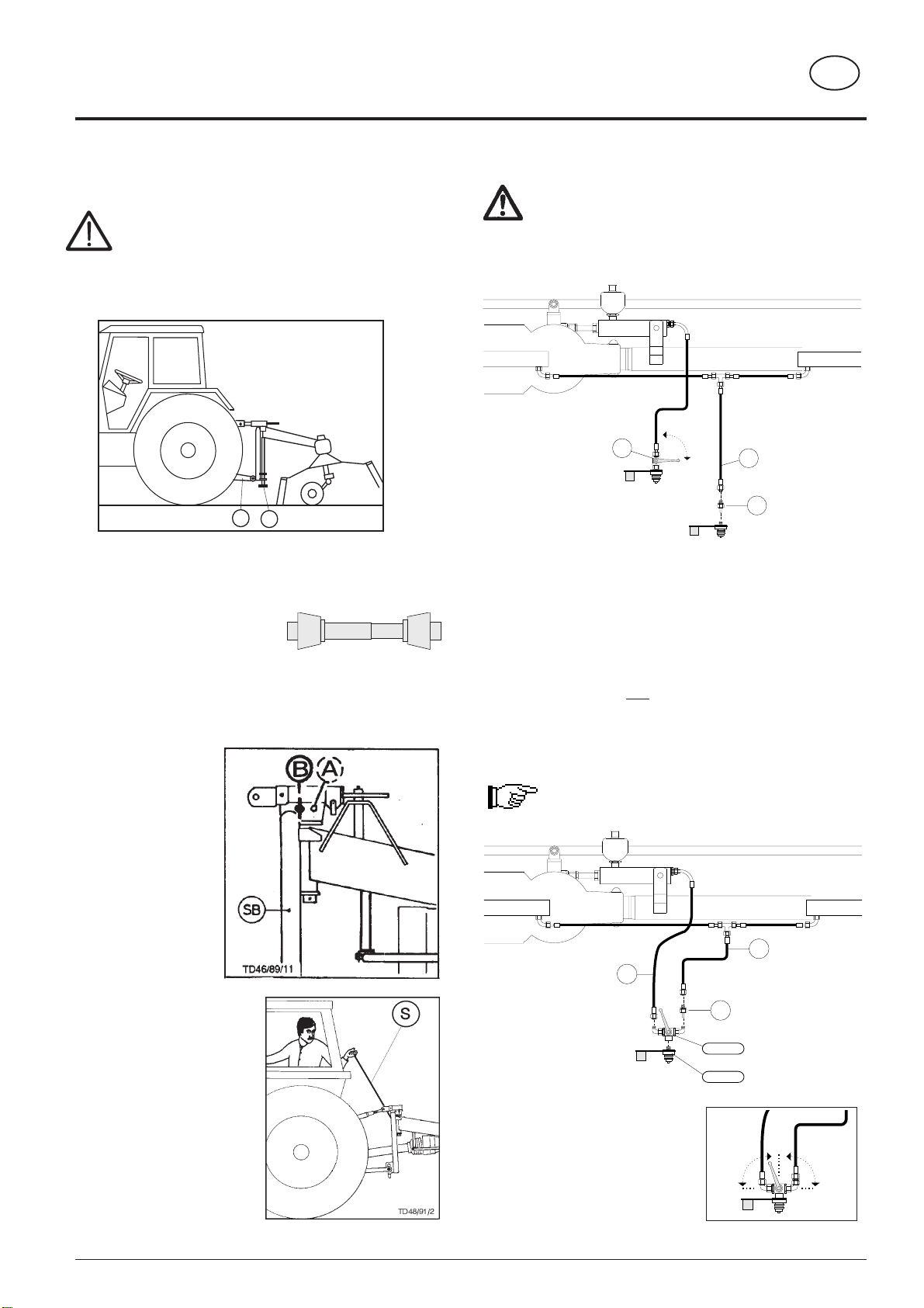
Hitching of machines with three point linkage ........................................ 5
Locking the headstock during use on roads and when lowering ........... 5
Release rope .......................................................................................... 5
Note ....................................................................................................... 5
HITCHING =================================== 5
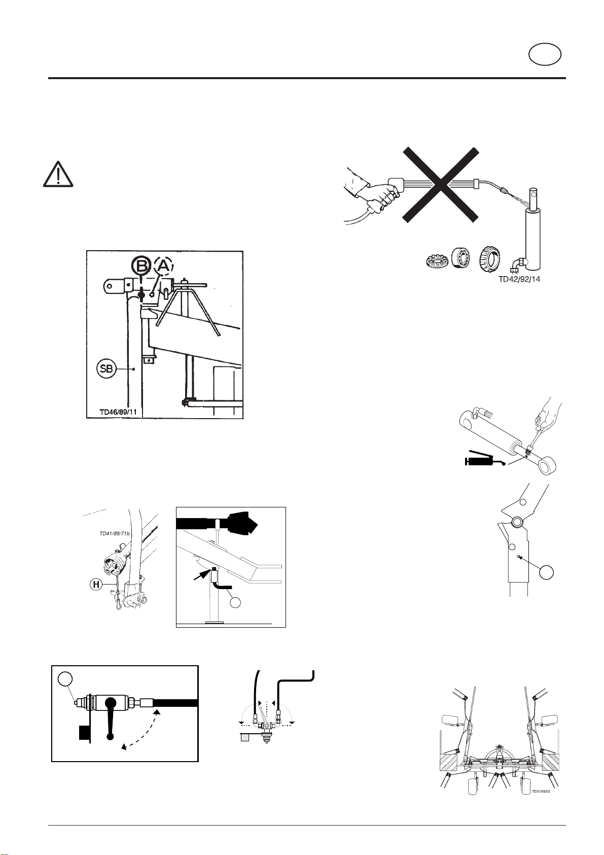
Lowering the rotary tedder ..................................................................... 6
LOWERING THE MACHINE====================== 6
Cleaning of machine parts ..................................................................... 6
Parking in the open ................................................................................ 6
Winter storage ........................................................................................ 6
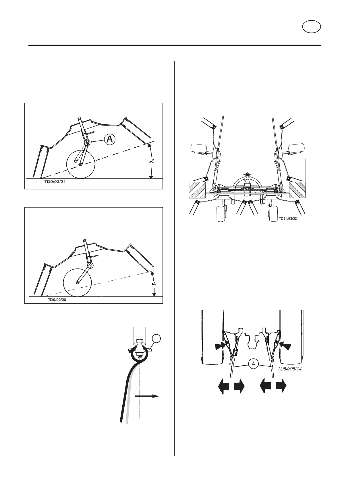
Adjustment of rotor inclination ................................................................ 7
Tine adjustment ...................................................................................... 7
ADJUSTMENTS BEFORE OPERATION ============ 7
Driving on public roads: ......................................................................... 7
Driving on public roads: ......................................................................... 8
Conversion from working to transport position ....................................... 8
Attention! ................................................................................................ 8
The order of operation must be adhered to. .......................................... 8
Locking the headstock during use on roads : ........................................ 8
TRANSPORTPOSITION========================= 8
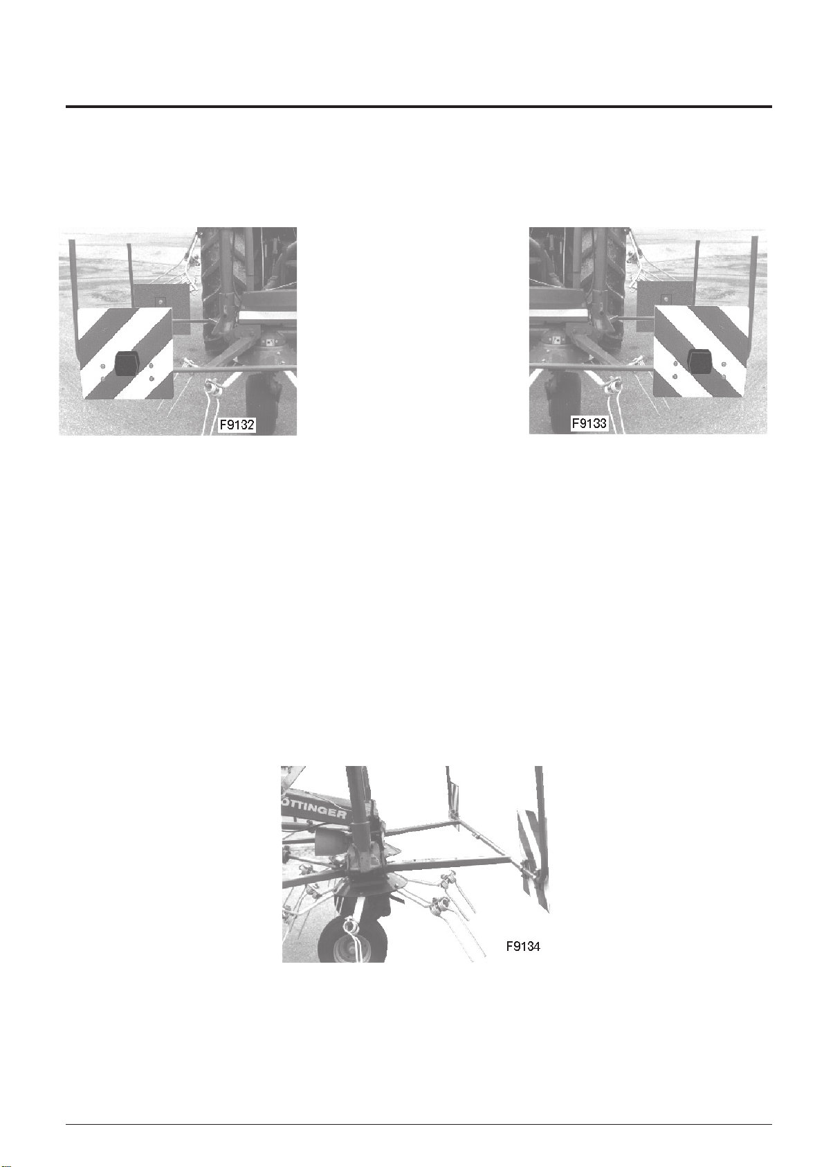
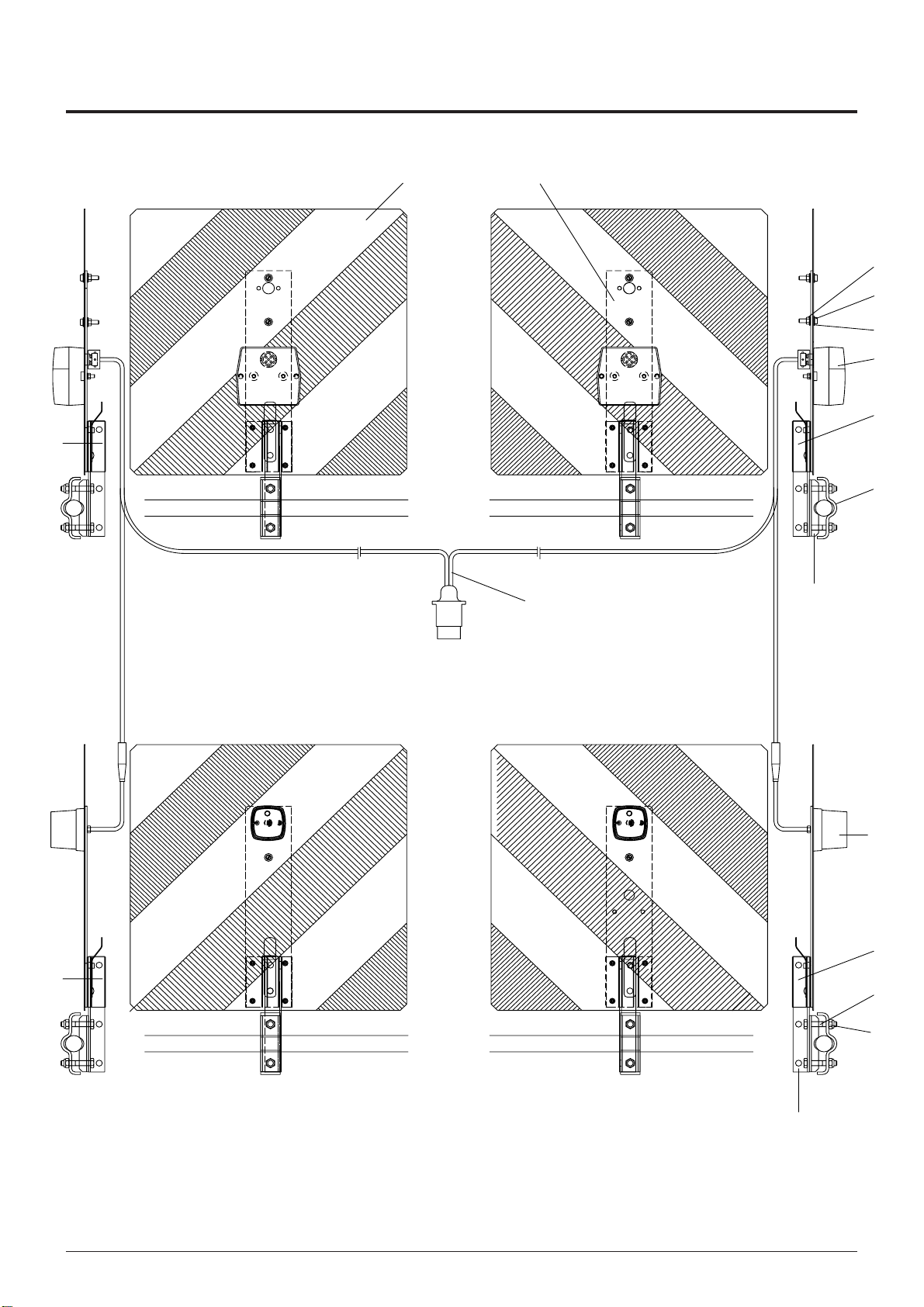
Warntafeln .............................................................................................. 9
Tableau de signalisation ......................................................................... 9
Warning plates ....................................................................................... 9
ECLAIRAGE ================================= 9
REMOVABLE LIGHTNING ======================= 9
Conversion from transport to workingposition ...................................... 11
WORKING POSITION ========================= 11
General guidelines for working with the machine ................................ 12
Beware! implements with three-point-linkage ...................................... 12
Operating on slopes ............................................................................. 12
Adjustment to implements with three-point-linkage: ............................ 12
Unterlenker fixieren .............................................................................. 12
P.t.o. speed .......................................................................................... 12
Tractor control device (ST) ................................................................... 12
Zinkeneinstellung ................................................................................. 12
USE ======================================= 12
Clearing field edges (border tedding) to the left or to the right ............. 13
Anti-vibration braces ............................................................................ 14
Remedy for noisy machine running ..................................................... 14
Turning manoeuvre in working position ............................................... 14
Maintenance and servicing .................................................................. 15
Intake transmission .............................................................................. 15
Changing tines ..................................................................................... 15
Gas container ....................................................................................... 15
Note ..................................................................................................... 15
Alteration of gas container pressure .................................................... 15
MAINTENANCE ============================== 15
Technical Data ..................................................................................... 16
Optional extras ..................................................................................... 16
Position of Vehicle Identification Plate ................................................. 16
TECHNICAL DATA =========================== 16
The defined use of the rotary tedder .................................................... 16
SUPPLEMENT =============================== 17
Recommendations for work safety ....................................................... 19
DRIVESHAFT ...................................................................................... 20
Lubrication chart .................................................................................. 21
Important! Additional Information ......................................................... 25
Combination of tractor and mounted implement .................................. 25

Hitching of machines with three point
linkage
Safety hints:
see supplement-A1 points 7.), 8a. - 8h.)
1. Pinning the machine to the three point linkage.
2. Fix the hydraulic lower link (4) in such a way that the
machine cannot swing out sideways.
3. Push in the support foot (5) and secure.
- Before using for the first time, the length of the drive shaft
must be checked and adjusted if
necessary (see also supplement
B "Drive shaft adaption").
Locking the headstock during use on
roads and when lowering
For transport the
headstock (SB) must be
locked using a lock nut.
A = working position
B = transport position
Important!
Only reposition the lock
pin when the machine
isin the raisedposition.
Release rope
- Run rope (S) into tractor
cabin.
Connecting hydraulic system to the tractor
For reasons of accident prevention the p.t.o. must be
switched off and the rotors must come to a stand still
before raising the side rotors.
- Only connect hydraulic system to the tractor when stopcock
is closed (position A).
Note
•Hydraulic line L1 is available in every model.
•For machines with hydraulic wheel adjusting equipment it is
necessary to have a second simple functioning hydraulic
connection on the tractor. The two-way stopcock (H2) is
connected to this.
•If the tractor only has one hydraulic connection, then instead
of a two-way stopcock (H2), a three-way stopcock (order no.
445.059) and the plug (order no. 448.051) which goes with
it can be fitted.
This means any individual hydraulic circuit can be selected.
With this connection variation, the backflow choke
valve (D) may not be removed.
Position A: Stopcock closed.
Position E1: Swivelling of outer
rotors.
Position E2: Swivelling of wheels.
TD12/93/15
L1
H2 A
E
D
TD12/93/13
A
E1 E2
TD12/93/14
445.059
448.051
L1
D
L1
TD34/90/4
5
4
HITCHING
GB
212 / ANBAU 9500-GB
- 5 -

Cleaning of machine parts
Attention! Do not use high-pressure washers for the
cleaning of bearing- and hydraulic parts.
- Danger of rust!
- After cleaning, grease the machine according to the
lubrication chart and carry out a short test run.
- Cleaning with too high pressure may do damage to
varnish.
Parking in the
open
When parking for longer
periods in the open, clean
plungerrodsandthencoat
with grease.
Check when parking
•So that rain water can run off
unhindered, the holes " W" must
not be blocked.
Winter storage
- Thoroughly clean machine before storage.
- Put up protection against weather.
- Protect exposed parts from rust.
- Lubricate all greasing points according to lubrication
chart.
- Park machine with
liftetrotors,which will
protect plunger from
rust.
TD32/90/12
A
E
60
TD12/93/13
A
E1 E2
FETT
TD49/93/2
W
TD7/95/5
Lowering the rotary tedder
The machine can be lowered both from the working position and from
the transport position.
Danger of tipping
Park the machine on firm, level ground.
If the ground is soft then the area where the support foot is to
stand must be appropriately increased using a suitable aid
(e.g. wooden board).
- Unpin bolt on the slewing headstock (SB) in position A.
Important!
Only reposition bolts when the machine is in the raised position.
- Lower the machine with the tractor hydraulic system and place on
support foot.
- Pull off drive shaft and rest on support.
Do not rest drive shaft on safety chain!
- Close stopcock (position A).
- Unhitch machine from tractor.
- Remove hydraulic cables.
TD9/92/14
10
- 6 -
LOWERING THE MACHINE
9500 GB ABSTELLEN (209)
GB

Adjustment of rotor inclination
The cog enables the darrier axles to be adjusted within a swivel
range.
1 setting = 1°alteration to rotor inclination
A lot of fodder = greater angle
Not much fodder = smaller angle
Tine adjustment
It is also important that tine inclination
is correct (see chapter "USE").
Driving on public roads:
•Observe the official regulations of your country.
•Travellingonopen roadsmay onlybe carriedoutasdescribed
in chapter "Transport position".
Hydraulic lower link
- Fix the hydraulic lower link (U) in such a way that the machine
cannot swing out sideways.
S1S2
80
TD 16/96/2
R
- 7 -
9600-GB VOREINSTELLUNGEN (212)
GB
ADJUSTMENTS BEFORE OPERATION

Driving on public roads:
Safety Precaution!
Changing from working
positiontotransportposition
is only to be carried out on
even, firm ground.
Only transport the machine
in the transport position!
Conversion from
working to
transport position
For safety reasons, turn off drive shaft and wait for rotor
to stop completely.
- Make sure that swivel area
is free and that nobody is
standing in the danger
area.
- Stopcock opened (position E)
Attention!
The order of operation must be
adhered to.
1.Pull rope (S). The stop function is raised.
2.The outer rotors are raised into the transport position by
actualing the control valve (ST).
3.Release rope (S) during
swivelling procedure so that
locking hooks can engage.
A
E
TD31/90/21
- Close stopcock (position A).
Attention !
- Check whether the locking hooks (10) are locked
into position correctly.
Locking the headstock during use on
roads :
For transport the headstock (SB) must be locked using a lock
nut.
B = transport position
Important!
Only reposition the
lock pin when the
machine is in the
raised position.
A
E
TD31/90/21
10
TD31/93/33
ST
GB
TRANSPORTPOSITION
TRANSPORTSTELLUNG 9600-GB (212)
- 8 -

Warntafeln
Tableau de signalisation
Warning plates
Einzelteile
siehe Ersatzteilliste.
Pièces détachée voir liste des pièces de
rechange.
For single parts see spare parts list.
209 / BELEUCHTUNG / 9600-D/F/GB
- 9 -
BELEUCHTUNG
ECLAIRAGE
REMOVABLE LIGHTNING

209 / BELEUCHTUNG / 9600-D/F/GB
- 10 -
BELEUCHTUNG
ECLAIRAGE
REMOVABLE LIGHTNING
TD 42-96-1
12
9
8
12
15
14
13
2
4
7
6
11
1
10
4
5
3

Conversion from transport to workingposition
Safety Precaution!
Changing from working position to transport position is only to be carried
out on even, firm ground.
- Stopcock opened (position E)
- Make sure that swivel area is free and
that nobody is standing in the danger
area.
- With hydraulic raising: move the control valve (ST) briefly to the "raise" position
simultaneously pulling on the rope (S).
Doing this releases the mechanical locks.
- Position tractor's servo-valve (ST) at "lower". The rotor is swivelled down to
working position.
- Pin the bolts on the slewing headstock (SB) into position A.
Important!
Only reposition bolts when the machine is in the raised position.
A
E
TD31/90/21
ST
GB
WORKING POSITION
- 11 -
9600-GB ARBEITSSTELLUNG (212)

General guidelines for working with
the machine
All work in the immediate area of the rotors may only
be carried out when the p.t.o. is switched off.
Caution! Do not enter rotor area while driving
motor is running.
- Choose the speed of travel so that all crops are
picked up thoroughly.
- In cases of overloading, shift down one gear.
- Liftthree pointfollowermachine beforegoing around
sharp bends and when reversing.
Beware! implements with three-
point-linkage
Machineswingsautomatically back to central
positionwhenliftedandislockedintoposition.
Take care that the swinging machine does not
endanger anybody and does not hit solid
obstacles. When lowering the machine the
locking devise is automatically lifted.
Operating on slopes
Take note! implements with three-point-
linkage
If the implement is being raised by the lifting gear
whilst travelling in a curve, the implement swings
automatically into the central position. If working on
slopes this can lead to dangerous situations, partly
due to the balance weight of the implement.
•The function of the shock absorbtion struts is to allow
the swinging procedure to be executed slowly and
continuously, not in jerks and jolts.
Important! Pay
attention to the
appropriate
setting of both
shock
absorberstruts
Adjustment to implements with three-point-
linkage:
-Adjust length of upper
link (9) so that rotors are
inclined forward and
spring tines lightly touch
the ground (see chapter
"Adjustment of rotor
inclination" also). Check
upperlink (9)adjustment
regularly during work
operation.
Unterlenker
fixieren
- Die Unterlenker (4) des
Schleppers müssen
seitlichspielfreiverriegelt
werden, um ein Hin- und
Herschwenken des
Zetters zu vermeiden.
P.t.o. speed
-P.t.o. speed max. = 540 rpm
The most favourable p.t.o. rpm is about 450 rpm.
Tractor control device (ST)
- Put tractor control device (ST) into
"free gear" (floating position or
"lower").
In this way the rotors adapt to
uneven ground.
TD34/90/8
4
9
TD49/91/23
495.173
S1S2
80
TD 16/96/2
R
TD16/96/1
80
Zinkeneinstellung
Durch Drehen des
Zinkenhalters(80)kann die
Zinkenstellung verändert
werden.
• Position "S1"
Standardeinstellung (ab
Werk)
• Position "S2"
Fürschwierige Einsatzverhältnisse,z.B.bei sehr
dichtem, schwerem Futterbestand. Die Streu-
wirkung wird mit dieser Zinkenstellung erhöht.
• Drehrichtung "R"
bei der Zinkenmontage beachten
ST
GB
USE
- 12 -
9600-GB EINSATZ (212)

GB
USE
- 13 -
9600-GB EINSATZ (212)
Clearing field edges (border tedding) to the left or to the right
Clearing field edges can be carried out by swinging the runner wheel.
1.) Swinging the runner wheel hydraulically on machines
with central adjusting equipment
- Open stopcock (position E with two-way stopcock).
PositionE1 whenusinga three-waystopcock(see alsochapter
"HITCHING").
- Operate servo-valve on the tractor.
To swing the runner wheel left move servo-valve to "lift"
position. To swing runner wheel right move servo-valve to
"lower" position.
2.) Swinging the runner wheel mechanically on
machines with central adjusting equipment
- Release locking bolts by pulling the rope (S).
- Turn the tractor wheels in the direction of the field edge and
drive forward at the same time. The machine's runner
wheels swing in the opposite direction.
- Let go of the rope (S) and make sure that the locking bolts
are correctly engaged.
Note
The slanting axles make border tedding possible with the three point machines. In this working
position the swivel area (9) is used to its full extent.
When driving around bends away from the edge of the field or at the end of the field, the machine
must therefore be lifted.
Attention!
The machine swings back into the central position (M).
TD12/93/9
S
TD12/93/8
A
E1 E2
A
E
TD31/90/21

GB
USE
- 14 -
9600-GB EINSATZ (212)
Anti-vibration braces
Anti-vibration braces bring about quiet machine running during operation.
Remedy for noisy machine running
Spring washer tension and friction element (R) pressure on the pressure can be altered
by turning hexagonal nut (SK).
Turning manoeuvre in working position
Implement with three-point-linkage:
- Raise implement using tractor's hydraulics.
TD48/91/13
TD27/91/1
SK R

Maintenance and servicing
Inorder tokeep themachine ingood condition evenafter alonger
period of operation, please observe the following notes:
- Afterthefirsthoursof operation, tightenall screws.
In particular the tine connections (12 kpm), the tine bar
connections (9 kpm) and the slewing headstock connections
should be checked.
- Always keep the stipulated air pressure in the tyres.
- Grease the lubrication points in accordance with the regulation
(see lubrication schedule).
Grease the lubrication nipples with universal grease after
every 20 hours of operation.
- Before leaving the machine over winter, oil all the joints well
and grease all bearings.
Intake transmission
The intake transmission runs in oil which must
be renewed or added to after every year of
operation:
- Pour gear lubricant oil into the
intake transmission (see
enclosure on fuel regulation).
Changing tines
- Remove broken tine after loosening the hexagonal nut and fit
new tine.
- For correct fitting observe the direction of the rotors!
- Tighten hexagonal screw with 12 daNm (= 12 kpm).
- Fit the safety shackle correctly (longer side (6) outside)!
- Bj. 2001: Using the tine gauge check the correct position of the
tine.
Gas container
Beware!
No welding, soldering or mechanical works of any kind
may be carried out on the container.
Note
•According to
manufacturer's
information all gas
containers have a slight
pressure drop after a
certain amount of time.
•The gas loss (nitrogen)
amounts to 2-3 % per
year.
•After 4-5 years it is
recommended that
container pressure be
checked and if necessary
corrected.
Alteration of gas container pressure
This work may only be carried
out by customer service or a
specialist.
In order to reduce or increase
the pressure in the gas
container a special filling and
checking device is necessary.
Pressure in the gas container: 80 bar Nitrogen (N).
TD12/93/10
Stickstoff
(N)
TD 7/95/3
Drehrichtung
direction of rotation
12 kpm
+ Bj. 2002 - Bj. 2001
MAINTENANCE
GB
- 15 -
0200-GB Wartung_209

M o dell
A. Pöttinger Maschinenfabrik Ges. m. b. H.
A-4710 Grieskirchen Oberösterreich
Masch.Nr.
Type Ges.Gew.
Position of Vehicle Identification Plate
The factory number is imprinted on the accompanying Vehicle
Identification Plate (as shown) and on the frame. Guarantee issues
andfurther inquiriescannotbe processedwithoutthe factorynumber
being stated.
Please enter the number onto the front page of the operating manual
immediately after taking delivery of the vehicle/implement.
Ihre/Your/Votre
Masch.Nr. / Fgst.Ident.Nr.
Technical Data HIT58N (Typ ZK212)
no. of rotors 4
Number of tine arms per rotor 6
working widh (m) 5,40 m
width of appliance in working position 5,80 m
maximum height 2,73 m
width swung up for transport 2,99 m
mass (kg) without drivershaft ~ 500 kg
Required power ab 13 kW
maximum p.t.o. speed (rpm) 540
Drivershaft torque limiter 800 Nm (80 kpm)
Tyres at the rotors 15,0x6,00-6 / 4 Ply rating / 1,5 bar
permanent sound emmision level 70 dB(A)
maximum permissible speed (km/h) 30 km/h
All data subject to revision.
The defined use of the
rotary tedder
The „HIT 58 N“rotary tedder is
intended solely for normal use in
agricultural work.
•Forthetedding, turningand raking
of green and raw fodder and
silage.
Any other uses outside of these
are regarded as undefined.
The manufacturer takes no
responsibility for any resulting
damagewhich occurs henceforth.
The risk is carried by the user
alone.
•The keeping of operating, service
and maintenance requirements
layed down by the manufacturer
also come under the heading of
„defined use“.
Optional extras
•Tyres at the rotors 16,0x6,5-8 / 4 Ply rating / 1,5 bar
•Shock absorbtion struts (see chapter "Use")
- for particularly quiet machine running when in use.
- for increased travel safely on slopes.
212 / TECHN. DATEN 9600-GB
TECHNICAL DATA
GB
- 16 -

GB-ANHANG TITELBLATT (341)
SUPPLEMENT

GB-ANHANG TITELBLATT (341)
The decision must be made, ”original”or ”imitation”? The decision is often governed by
price and a ”cheap buy”can sometimes be very expensive.
Be sure you purchase the ”Original” with the cloverleaf
symbol!
•Quality and precise fitting
- Operating safety.
•Reliable operation
•Longer lasting
- Economy
•Guaranteed availability through your
Pöttinger Sales Service.
Things will run better with
genuine Pöttinger parts
The original cannot be copied

(341) SICHERHEIT 9400 GB
SUPPLEMENT - A
Recommendations for work safety
All pointsrefering tosafety in thismanual are indicated
by this sign.
1.) Defined use
a. See "Technical Data".
b. The keeping of operating, service and maintenance
requirements layed down by the manufacturer also come
under the heading of "defined use".
2.) Spare parts
a. The original components and accessories have been
designed especially for these machines and appliances.
b. We want to make it quite clear that components and
accesories that have not been supplied by us have not
been tested by us.
c. Theinstallation and/oruseof suchproductscan, therefore,
negatively change or influence the construction
characteristics of the appliance. We are not liable for
damages caused by the use of components and
accessories that have not been supplied by us.
d. Alterations and the use of auxiliary parts that are not
permitted by the manufacturer render all liability invalid.
3.) Protection devices
All protection devices must remain on the machine and be
maintained in proper condition. Punctual replacement of
worn and damaged covers is essential.
4.) Before starting work
a. Before commencing work, the operator must be aware of
all operating devices and functions. The learning of these
is too late after having already commenced operation!
b. The vehicle is to be tested for traffic and operating safety
before each operation.
5.) Asbestos
- Certain sub-supplied components of the
vehicle may contain asbestos due to
technical reasons. Observe the warning
on spare parts.
6.) Transport of persons prohibited
a. The transport of persons on the machine is not permitted.
b. The machine may only be driven on public roads when in
the position stipulated for road transport.
7.) Driving ability with auxiliary equipment
a. The towing vehicle is to be sufficiently equiped with
weights at the front or at the rear in order to guarantee the
steering and braking capacity (a minimum of 20% of the
vehicle’s tare weight on the front axle).
b. The driving ability is influenced by ground conditions and
by the auxiliary equipment. The driving must be adapted
to the corresponding terrain and ground conditions.
c. When driving through curves with a connected appliance,
observe the radius and swinging mass of the appliance.
d. When travelling in a curve with attached or semimounted
implements, take into account the working range and
swing mass of the implement!
8.) General
a. Before attaching implement to three-point linkage, move
system lever into a position whereby unintentional raising
or lowering is ruled out!
b. Dangerof injuryexists whencoupling implement totractor!
c. Danger of injury through crushing and cutting exists in the
three-point linkage area!
d. Do not stand between tractor and implement when using
three-point linkage external operation!
e. Attachand detach drive shaftonly whenmotor has stopped.
f. Whentransporting with raisedimplement, secure operating
lever against lowering!
g. Before leaving tractor, lower attached implement to the
ground and remove ignition key!
h. Nobody is to stand between tractor and implement without
tractor being secured against rolling using parking brake
and/or wheel chocks!
i. For all maintenance, service and modification work, turn
driving motor off and remove universal drive.
9.) Cleaning the machine
Do not use high-pressure washers for the cleaning of
bearing- and hydraulic parts.
20%
Kg
- A 1 -
Recommendations for work safety

0000-GB GELENKWELLE (341)
DRIVESHAFT
GB
Supplement - B
1) How a cam type cut out safety clutch works:
This overload clutch switches
the torque transmitted to zero
if overloaded. To revert to
normal operation, stop the
p.t.o. drive briefly.
The clutch reengages at a
speed below 200 rpm.
IMPORTANT !
The overload clutch on the driveshaft is not a “Full up”indicator. It
is purely a torque limiter designed to protect the implement against
damage.
Driving the right way will avoid triggering the clutch too often, and
thus causing unnecessary wear on it and the implement.
2) Wide-angle joint :
Maximum angle of deflection when working/stationary : 70°
3) Standard joint :
Maximum angle of deflection
when stationary: 90°
Maximum angle of deflection
when working: 35°
Maintenance
Replace worn-out
covers/guards at once.
- Lubricate with a brand-
name grease before starting work and every 8 hours worked.
- Before any extended period of non-use, clean and lubricate
driveshaft.
For winter
working, grease
the tube guards,
to avoid them
freezingtogether.
•Important for driveshafts with friction
clutch
Prior to initial operation and after long periods out
of use, check friction clutch for proprer function.
a.)Measure dimension„L“atcompression spring
of K90, K90/4 and K94/1 or at set screw of
K92Eand K92/4E.
b.) Loosen screws to release the pressure on the
friction disk.
c.) Tighten set screws to dimension „L“.
Clutch is ready for use.
DRIVESHAFT
Important! Only use the indicated or
accompanyingdrive shaft,otherwise
the right to claim under guarantee for
any possible damage does not exist.
Matching driveshaft to tractor
To determine the actual length
required, hold the two halves of the
driveshaft side by side.
Procedure for cutting to length
- To determine length required, set implement in closest working
position (L2) to tractor, hold driveshaft halves side by side and mark
off.
Important!
•Note the maximum
operatinglength (L1)
- Try to attain the
greatest possible
shaft over-
lap (min.
1
/
2
X)!
•Shorten inside and
outside tube guard
bythe same amount.
•Fit torque limiter (2) of drive
shaft to implement end of
driveshaft!
•Always check that drive shaft
locks are securely engaged
before starting work.
Retaining chain
- Usechainto preventtube guard
from rotating.
Take care that chain does not
impede driveshaft pivoting.
Rules for working
Neverexceed themaximum p.t. o.
speed when using the implement.
- When the p.t.o. is switched off,
the implement hitched up may not stop at once.
Do not go close to the implement until all motion has stopped; only
then may work be done on it.
- When the implement ist
parked, either remove the
driveshaft and store it, or
secure it with a chain. (Do not
useretainingchain(H)for this).
X
X
L1
L2
X
X
min.
TD 52/97/37
- B 1 -
8
h
FETT
L
L
K92E,K92/4E
K90,K90/4,K94/1
This manual suits for next models
1
Table of contents
Other Pottinger Tedder manuals