pottorff CD-25R-CO2 User manual

POTTORFF
®5101 Blue Mound Road, Fort Worth, Texas 76106 www.pottorff.com
Information is subject to change without notice or obligation.
NOTE: Dimensions in parentheses ( ) are millimeters.
Control Dampers, Room Sensor IICD25RCO270227 Rev. A (1/3) May 2022
CD-25R-CO2low leakage control dampers employ a sturdy round
frame, a single round blade for automatic air control, and a modulating
Belimo actuator controlled by a wall-mounted CO2sensor.
Application
The following guidelines provide basic setup and installation
instructions for the CD-25R-CO2modulating damper with the room
sensor option.
General
Check for obvious and hidden package damage after receiving. Check
to be sure that all parts of the shipment, including accessories, are in
the package. Dampers must be kept clean and dry. Indoor storage and
protection from dirt are highly recommended.
If there is a question about the condition of the damper or the
installation process, please call customer service at 817-509-2300.
Receiving and Handling
After visually inspecting the damper, store it indoors, and protect it
from sunlight, moisture, and flooding. Protect dampers from debris and
dirt accumulation. Keep all conduit plugs and actuator access covers
in place.
Proper storage of the damper intends to prevent physical damage,
material corrosion, and deterioration of organic material.
Note: It is the responsibility of the installer to verify the
structural integrity of the existing structure to support the
loads imparted by the damper.
Storage of Dampers Before Installation
Warnings
1. Do not use the actuator or axle as a lifting point.
Dont’s
1. Align the damper with the existing duct work.
2. Verify the airflow direction.
3. Install and support the damper per all applicable SMACNA
guidelines.
4. Mount the sensor in the duct within the manufacturer’s
guidelines.
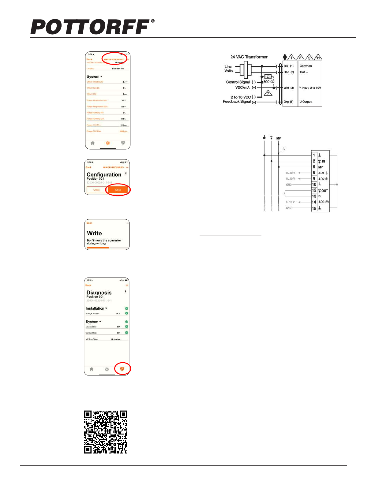
5. Wire the actuator into the transformer.
6. Wire the sensor to both the actuator and transformer.
7. Move the sensor wire terminals to their proper location on the
PCB board.
8. Wire transformer into the 120V building power.
9. Restore power to the system.
10. Verify the movement of the blade after installation.
11. Follow the sensor commissioning process below.
Installation Details
1. Read the installation instructions thoroughly before installing
or servicing this equipment. Improper installation, adjustment,
service, or maintenance may lead to property damage, injury,
or death.
2. Disconnect the power supply to the damper before making
any wiring connections to prevent the danger of electrical
shock or equipment damage.
3. All wiring must comply with all applicable local and national,
electrical and safety codes. Consult local codes for further
guidance.
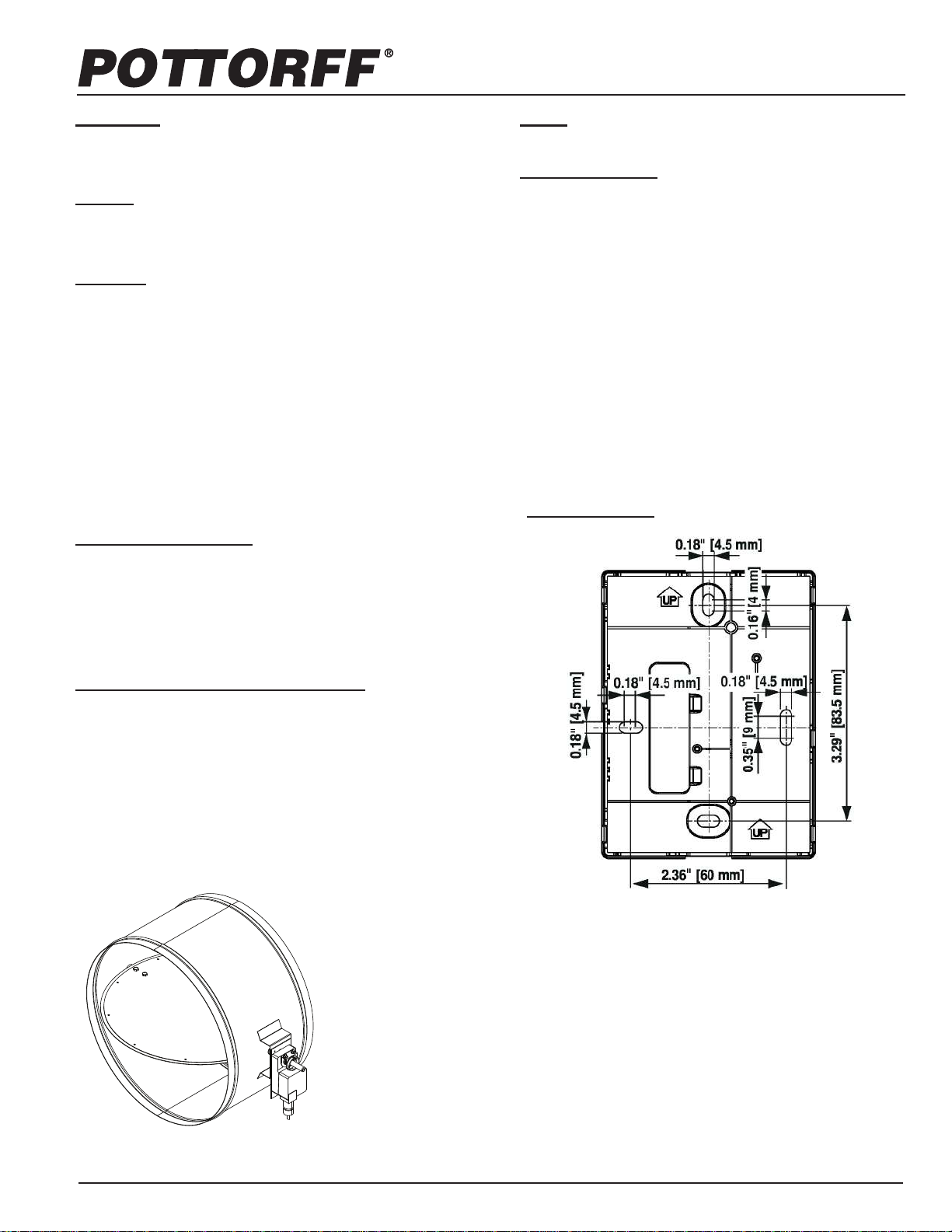
4. When picking where the fresh air intake is placed, be cautious
of possible contaminants or blockages. Sensor Mounting
Model CD-25R-CO2
(standard)
*Damper dimensions furnished
approximately 1/8" (3) undersize.
model CD-25R-CO2
low leakage CO2control damper
installation instructions - room sensor

POTTORFF
®5101 Blue Mound Road, Fort Worth, Texas 76106 www.pottorff.com
Information is subject to change without notice or obligation.
NOTE: Dimensions in parentheses ( ) are millimeters.
Sensor Commissioning
1. Download the Belimo Assistant App from Google Play or the
Apple App Store.
4. When the scan is complete, an overview screen will load
showing the current sensor readings.
5. Navigate to the Configuration tab using the gear icon located
at the bottom center of the screen.
2. Connect to the NFC chip within the sensor
a. A Bluetooth Converter may be required when
connecting with an iPhone.
i. Belimo Part Number: ZIP-BT-NFC
b. Pair the converter to the phone by navigating to the
connection settings menu using the 3 bars in the top
right before linking the converter to an NFC chip.
c. When linking the converter, focus the round
hole the center of the sensor’s faceplate.
7. Adjust the CO2Range:
a. CO2Min: 800 ppm
b. CO2Max: 1,200 ppm
6. Add a location name.
a. Ex.: Office 1
3. The scan will begin automatically.
Note: The following will only be needed during the initial
Note: The range can be set to anywhere between 0
ppm and 2,000 ppm, the above is recommended for
proper functionality.
Control Dampers, Room Sensor iiCD25RCO270227 Rev. A (2/3) May 2022
model CD-25R-CO2
low leakage CO2control damper
installation instructions - room sensor

POTTORFF
®5101 Blue Mound Road, Fort Worth, Texas 76106 www.pottorff.com
Information is subject to change without notice or obligation.
NOTE: Dimensions in parentheses ( ) are millimeters.
If needed, clean the damper with soap and warm water to remove dirt
that may collect and cause hindrance to airflow.
CO2Room Sensor Wiring Diagram
Actuator Wiring Diagram
Wiring Diagrams
Damper Maintenance
Foreign Matter
Make sure there is no obstruction to parts that are intended to move freely
such as axles, blades, etc.
Moving Parts
There should not be any foreign materials interfering with the bladed
closure. Any interference may keep the damper from functioning properly.
Closure
Replacement is recommended if the seal is damaged or worn to reduce
the potential for leakage. Consult the factory for a replacement seal.
Blade Seal
Cycle test actuator per manufacturer’s recommendations.
Actuator
Drifting will occur due to the aging process of components; however, the
sensor is equipped with dual channel technology which allows for
self-calibration. Manual calibration is not needed.
Sensor Calibration
Control Dampers, Room Sensor iiCD25RCO270227 Rev. A (3/3) May 2022
10. For video instructions, visit the following link or the Belimo
website:
https://e.videocdn.net/share?videoid=2HisCEAnfMNCqWMpfDDUyT
&player-id=7M1TCJV-E7NekEUkhw4osh
b. Reconnect the app to the sensor using the NFC chip
or Bluetooth Convertor. Do not move the convertor or
phone when pairing.
9. Navigate to the Diagnostics tab to check the electrical state of
the sensor.
a. The heart icon located in the bottom right corner of the
screen.
2...10 V / 4...20 mA Control
GND = 1
AC/DC 24 V = 2
MP Bus = 5
Output Temperature = 8
Output Humidity (22RTH / 22RTM) = 9
GND = 10
Digital Input, e.g.presence detector = 12/13
OutputCO₂ (22RTM)= 14
8. At the top of the screen “WRITE REQUIRED” will flash.
Select it.
a. Select Write
model CD-25R-CO2
low leakage CO2control damper
installation instructions - room sensor
Popular Accessories manuals by other brands

Goalsetter
Goalsetter Signature Series Installation and owner's instructions

Vuly
Vuly ULTRA Assembly manual

Dwyer Instruments
Dwyer Instruments OSC-200 Installation and operating instructions

Carel
Carel WS01W02M Series Guide

Microsonic
Microsonic lcs+340/F operating manual

PORSCHE DESIGN
PORSCHE DESIGN P'3110 instruction manual