Powelectrics Metron 4 User manual

Connecting
Sensors to
the Internet
of Things
Temperature
Level
Pressure
Meter
Vibration
Flow
Wind speed
Wind direction
Humidity
CO2
Distance
Hours run
Fault
Intruder
Collision
State
Weight
pH
Conductivity
Salinity
TOC

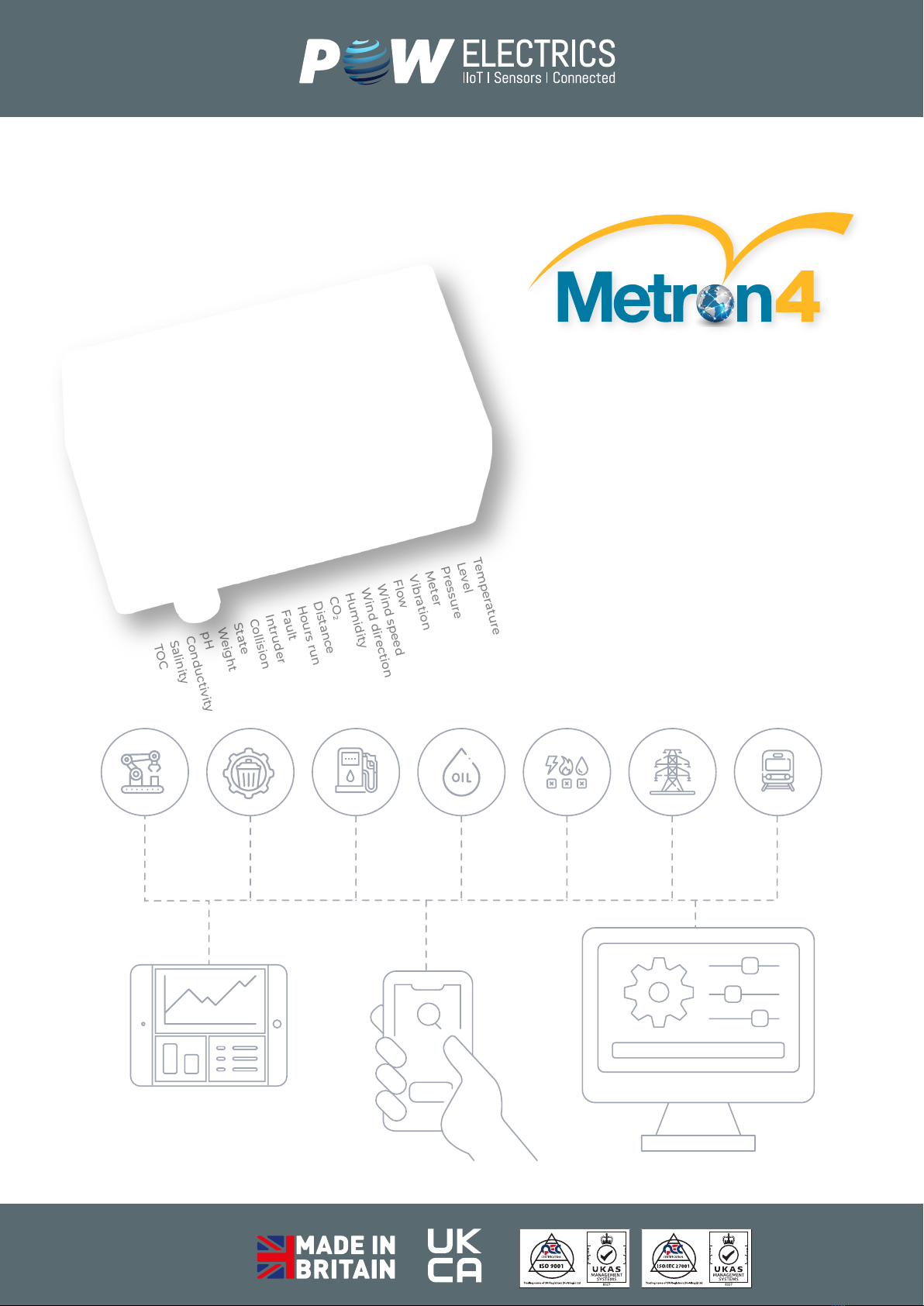
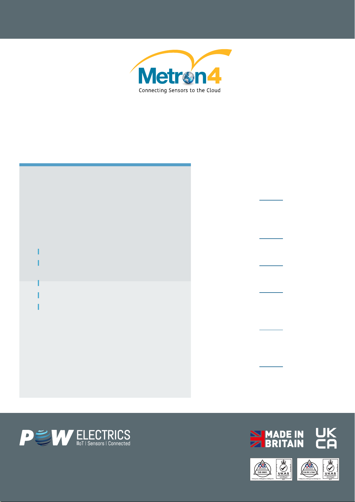
Getting to Know… The Metron4
The Metron4 makes remote monitoring
simple and affordable, interfacing with
sensors, taking periodic readings and
transmitting them over the mobile
phone networks.
• Compatible with 1000s of sensors
• Remotely programmable
• Self-contained, weatherproof
• Proven and reliable
Intelligent solar regulator maximises battery life and solar charging potential and
includes pre charge conditioning if battery is in poor condition. There is also
temperature com pensation, meaning charge rate is adjusted according to battery
temperature, maximizing battery life.
Solar capability depends on orientation, sight of sun and location ( ie the further
from the equator the less power from the sun). In England, 10 minute transmissions
possible, in Scotland need a 2nd solar cell to achieve this.
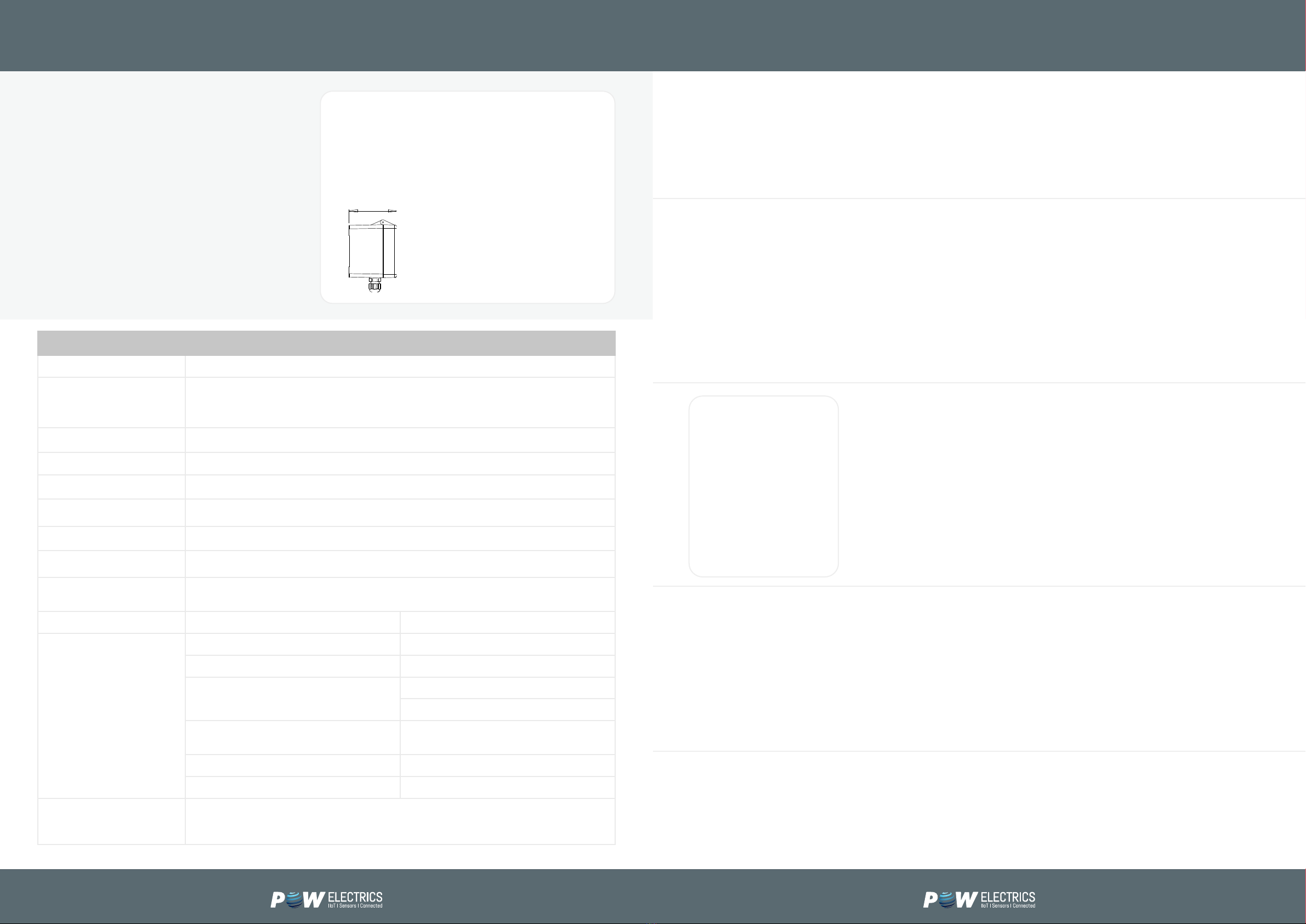
Dimensions
185 × 337 mm base plate
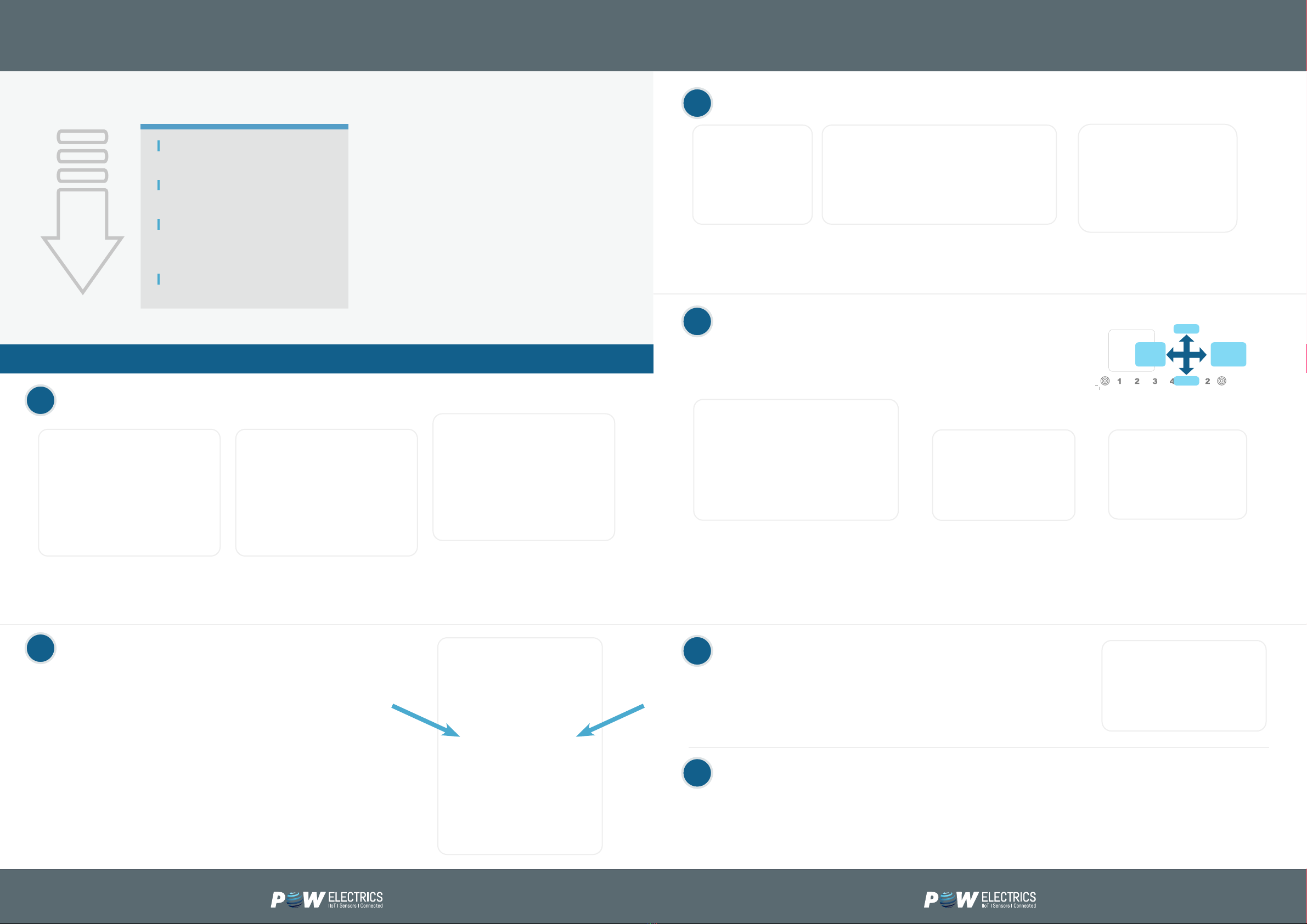
The Metron4 is housed in a panel with the barriers. This panel needs to be in the safe area and
suitable sensors tted in the eld.
This augmented solution offers a sophisticated interface on site, with high resolution, colour
display of actual process (eg tank levels & graphics). It is used where more complex calculations
and commands are needed on site. MetronAS offers instant response to programmable inputs/
events, triggering immediate alarms and beacons Contact Powelectrics to discover more about
MetronAS and bespoke, application specic solutions.
Enclosure
400 × 300 mm wall mount panel with
hinged door.
ATEX Barrier(s)
Includes up to 4 ATEX barries,
such as MTL 554.
Sensor Cabling
Consider inductance and capacitance of cable
as well as characteristics of sensor.
For SPS Ex (from Powelectrics) with
LAPP12420 cable max. = 754m.
Metron4/S/SOL SYS runs from a 10 Watt solar power
and lead acid battery via an intelligent charge regulator.
Metron4/S/...ATEX for use in explosive atmospheres. For 110/230 Vac power supply.
MetronAS (Augmented Solution)
Technical Specications
Parameter Details
Inputs
4 (4 – 20 mA, 0 – 10 V DC sensors or volt free contacts).
Expansion cards: 5 channel pulse (volt free, 10 Hz max.) & RS232 / R S485
(contact Powelectrics regarding protocols).
Outputs Optional 2 relay outputs controlled either remotely or when threshold breached.
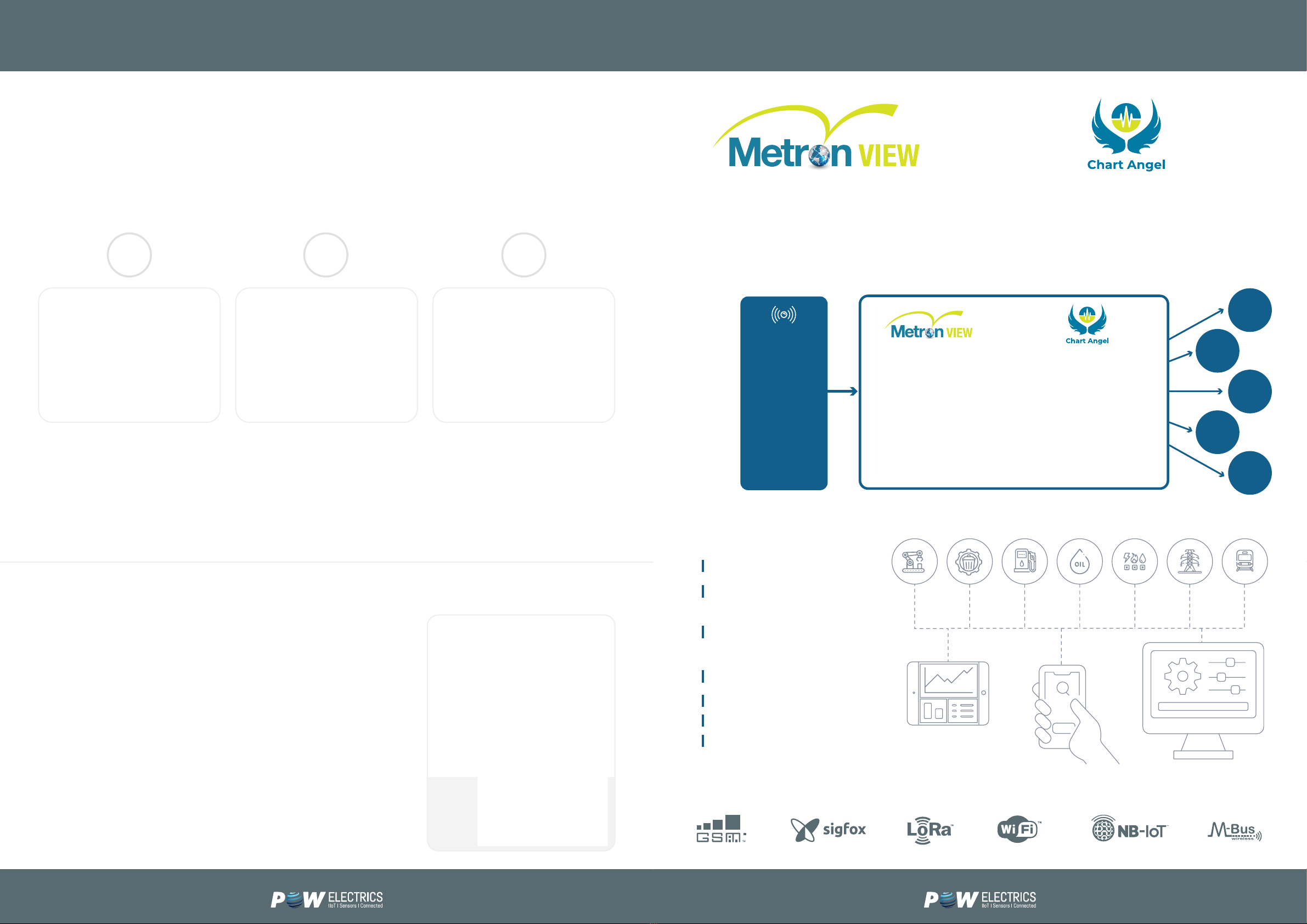
Communications GSM (4G (CatM1 / NB1) with 2G fallback – worldwide frequencies).
Data Logging 80 per channel, rst in rst out.
Power Supply Battery, 6 – 24 Vdc, 110/230 Vac, internal battery and solar options.
Sensor Excitation Will provide power to sensors (5 V or 21.6 V, 31 mA max.) for a programmable length of time.
Environmental IP67, -20 to +65ºC.
Programming Normally remotely from MetronVIEW or locally via USB (Windows software free of charge from
Powelectrics. Mini USB not provided by Powelectrics).
Congurable Parameters System Inputs
Wake up interval (min: 1 min, max: 24 hr) Type (analogue or digital)
Transmit interval (min: 5 min, max: 24 hr) Tag name
Modem state (including idle, transmit on power
up, pollable)
Units of measure
Zero & span (scaling) and linearisation
Antenna selection (internal or external) Alarm thresholds (10 high (rising) and 10 low
(falling))
Synchronisation time Call out delay
Transmission window Sensor excitation time and settling voltage
Display
The built-in back lit 40x40mm LCD display acts as a local gauge to help test the device and ensure
it is communicating well. It is also used to check sensors and wiring. Can be used as a local display
to show measured values on wake up.
138
75
68
Metron4/S runs on 6-24Vdc. Allow 0.5 A. Ensure supply is well regulated.
For mains power 110/230 Vac, options are:
/MPSU Mains (110 / 230 Vac)
power supply with backup
battery and regulator, housed in
a weatherproof enclosure and
a Metron4 xed on base plate
(185 x 371 mm). Provides 6 Vdc
to Metron4
UPS 12 V Uninterruptable power
supply is a separate box
(262 × 188 mm). Mains 110 / 230
Vac in 12 Vdc maintained output via
battery backup. Battery can typically
support 50 transmissions. IP54
protection rating. Run cable from UPS
12 V to Metron4.
Battery life depends on regime. The Metron4 is designed to maximise battery life. More
frequent readings, weak signal and cold temperatures will shorten battery life. Battery duration
also dependent on the type of sensor used. Typical life is 4 years if powering a 2 wire, 4-20
mA sensor for 2 seconds and transmitting once per day. Only use Powelectrics approved
batteries.
Metron4/SSM runs from an internal battery.

Expansion Cards
External Antenna
The Metron4 can have expansion cards tted such as a 5 channel pulse counting card, providing a system that has 4 analogue inputs
and 5 pulse inputs in total. Pulse inputs can be used for a variety of applications, including ow and electricity meter reading.
The expansion cards t neatly inside the Metron4 and present the terminals for easy connection of the pulse signals. The pulses
need to be slower than 10 Hz (10 pulses per second) and must be volt free contacts.
The count can be congured to either reset when successfully transmitted to the server, or rollover (can count to 4,294,967,295).
Powelectrics web-based data collection platform is a exible, reliable and secure IIoT cloud, which receives remote monitoring data
from sensors, machines and IoT devices, providing data & alerts to unlimited users using any web-enabled device.
Intuitive functionality includes conguration wizards and libraries and ‘Chart Angel’ to overlay data from multiple devices for easy
identication of irregularities.
Insert card into Ex socket.
You will see the corresponding LED quickly ash when a pulse is seen, if tted correctly.
Also available: serial port RS232 & RS485. (Contact Powelectrics regarding protocols).
The Metron4 has an integral antenna and has been designed to achieve
optimal signal strength to the mobile phone networks. However, consider
connecting an external antenna too, if mounting in an area of poor signal
strength improve the signal or inside a metal enclosure.
The SMA connector present on the board usually requires a mating connector
that is too large to t through the standard M12 cable glands that are
supplied.
A tting kit is provided but if sourcing own antenna, an M12 – M16 cable
gland adapter will be required. Also consider the need to bore out centre to
get the connector through.
Select external antenna via menu or set in the conguration.
Wire in to green connector plug and
tighten screw.
Insert connector into plug
in terminal connector.
1 2 3
GSM
(2G/4G/LTE/NG1)
LoRa
RS232
RS485
Ethernet
Wi-Fi
CAN
MODBUS
IO-Link
Expandable IO
CURRENT
DATA
HISTORICAL
DATA
ALERTS
CUSTOM GUI’s
& REPORTS
3RD PARTY
SOFTWARE
Temperature
Level
Pressure
Meter
Vibration
Flow
Wind speed
Wind direction
Humidity
CO2
Distance
Hours run
Fault
Intruder
Collision
State
Weight
pH
Conductivity
Salinity
TOC
Metron4 Optional Additions MetronView
Hosted software platform
Receives data from the
Metron4 and other remote
IoT devices
Allows for viewing of data via
internet connected devices in
any browser
Remote Metron conguration
Alarms sent by email
Pull data via API
Safe and secure

Metron4 Quick Start Guide Metron4 Quick Start Guide
Metron4 Quick Install Guide
The system is usually set up so unit
powers down between readings.
The real time clock counts time and
wakes the device up depending on how
it is programmed.
10 high and 10 low alarm thresholds for
each of the 4 channels – if threshold
is breached then Metron4 transmits
immediately. The unit can log 80
readings per channel.
Unpack & Open Up the Metron4
Connect the Sensors & Power
Navigate the Metron4
View Data
Programming
Mount the Metron4
Place the unit on a at surface and
loosen the 2 nylon screws in the bottom
corners to open. Allen key required.
Run the sensor’s cable
through the gland.
Use the 2 mounting holes used to fasten the Metron4 down to a baseplate,
wall or other surface.
The unit needs a mobile phone signal to operate, so try to avoid mounting
inside metal cabinets or underground. The unit is weatherproof, but ensure:
• All cable glands and breather glands on the unit have an ‘O’ ring tted
and are sufciently tightened.
• If no cable is going through the gland, that blanking plugs are tted.
Blanking plugs also need tting over the xings inside the device.
• Both screws on the top are tightened, but not over tightened.
• The seal around the lid is correctly in place.
Open the Metron. The interior will vary
depending on unit. The image shows the
/SSM model with a battery.
Unplug the green connector and wire in
as required.
Ensure the SIM card is installed.
Plug the connector into the correct input
channel and tighten the gland. Ensure cable is
through the gland. Plug in the power source.
Press any button to wake up the Metron4 and enter
PIN (default = 1234). Press right after 4th digit to enter.
Force transmit. Move down to Force Transmit,
and right to select. Watch the progress bar and
wait for the unit to transmit. Once complete, the
data will be available for viewing on MetronView.
The unit will countdown for 40 seconds then
enter Run Mode. The screen will turn off.
Login details will normally be sent by email. If not, contact Powelectrics support.
Once logged in, a summary of your units will be visible. Click on view to the left
of the device’s name to see the historical data. Powelectrics support can change
the name of units and inputs if required.
Units can be remotely programmed from MetronView. It is possible to change how often readings are taken & sent, alter scaling
and alarm thresholds for each of the input channels and much more (see Congurable Parameters earlier). To make changes
please contact Powelectrics support. The conguration will be held on the server and be downloaded to the device when it next
communicates, and then use the new settings in the future. Select ‘Force transmit’ rather than waiting for the next time the device
transmits in order to recongure sooner.
Check signal. Enter PIN, select
System, select Get Cong /
Signal. Signal is scaled between
0 -31 (31 = best) and at least
10 recommended for GSM
connection.
Immediate reading. Touch
device to wake and left for live
reading. Keep pressing left to
swap between channels and
read different sensors.
Go back
a level of
the menu
Select the
highlighted
option
Up
Down
Unit asleep; screen
and GSM off
Wake up interval – powers the
sensors and takes readings
Transmit interval (or upon
alarm) it powers up the GSM
engine
Readings & alarms are
sent via GSM
1
3
4
5
6
2
How Metron4 Works

Remote Condition
Monitoring
Lower Operational &
Maintenance Costs
Extend Asset Life
Improve Safety
Enhance Sales
Propositions
Introduce New
Revenue Streams
Improve Service
Powelectrics offer over 30 years’ experience delivering data to drive business decisions. We
connect sensors to the cloud to generate efciencies and inform management strategy. Our
proprietary IIoT technology is, robust and intuitive, proven and constantly evolving. We can
integrate with third party instrumentation and software to develop bespoke solutions for
any size of organisation, across a huge range of sectors, anywhere in the world.
Connecting assets to the cloud is now essential
for businesses to remain competitive.
Powelectrics’ innovative Metron4 IoT telemetry
device (or sensor gateway) makes remote
monitoring simple.
Metron4 gets sensor data reliably and affordably
into the cloud via 4G (2G backup).
Compatible with thousands of sensors, Metron4
is ideal in a vast range of global environments
and applications.
In conjunction with our MetronView cloud,
Metron4 helps customers improve margin,
achieve competitive advantage and develop new
revenue streams.
Monitor. Control. Maintain. Alert.
4 analogue inputs,
Expansion cards for pulse counting,
options for RS232, RS485 and CANBUS
Compact IP67 enclosure
Solar, battery and external power options
Operational temperatures -25 to +65°C
Powelectrics Limited. 12 Ninian Park, Tamworth, B77 5ES
sales@powelectrics.co.uk +44(0) 1827 310 666
www.powelectrics.co.uk
Table of contents
Popular Accessories manuals by other brands

SUTO
SUTO S450 Instruction and operation manual

TeraBee
TeraBee TeraRanger Evo user manual

elsner elektronik
elsner elektronik KNX AQS/TH-B-UP Technical specifications and installation instructions

Stahl
Stahl SolConeX 8570/11 Series operating instructions

Safeguard Supply
Safeguard Supply WDK-ERA-KIT owner's manual

Leviton
Leviton OSW12-M installation instructions

Aeotec
Aeotec MULTISENSOR 6 user guide

ETC
ETC Echo Dual Tech Wall-mount Vacancy Sensor installation guide

Safeguard Supply
Safeguard Supply ERA-PBDCR-STROBE owner's manual

Sparehand Systems
Sparehand Systems Glacik G-505 quick guide

Balluff
Balluff BOD 26K Series Mounting and operating instructions

Airflow
Airflow RF MEV WH4H Operation and service guide