Power-Flo Pumps & Systems • 877-24PUMPS • www.poweropumps.com
7
Always rely upon a Certied Electrician
for installation.
Overload Protection:
Single Phase - The stator in-winding
overload protector used is referred to
as an inherent overheating protector
and operates on the combined eect
of temperature and current. This means
that the overload protector will trip out
and shut the pump o if the windings
become too hot, or the load current
passing through them becomes too high.
IMPORTANT ! - The overload will then
automatically reset and start the pump
up after the motor cools to a safe
temperature. In the event of an overload,
the source of this condition should be
determined and corrected immediately.
Pre-Operation
1. Check Voltage and Phase
Compare the voltage and phase
information stamped on the pump
name plate.
2. Check Pump Rotation - Improper
motor rotation can result in poor
pump performance and can damage
the motor and/or pump. Incorrect
rotation for Single-Phase pumps is
unlikely. If the rotation is incorrect
contact factory.
3. Name Plate - Record the information
from the pump name plate to
drawing in front of manual for future
reference.
4. Insulation Test - An insulation
(megger) test should be performed
on the motor. Before the pump is put
into service.
The resistance values
(ohms) as well as the voltage (volts)
and current (amps) should be
recorded.
5. Pump-Down Test - Be sure pump
has been properly wired, lowered into
the basin, sump or lift station, check
the system by lling with liquid and
allowing the pump to operate through
its pumping cycle. The time needed to
empty the system, or pump-down
time along with the volume of water,
should be recorded.
Replacement Parts are not
availlable for this unit.
Installation
PFUT06, PF30A Portable Utility Pumps
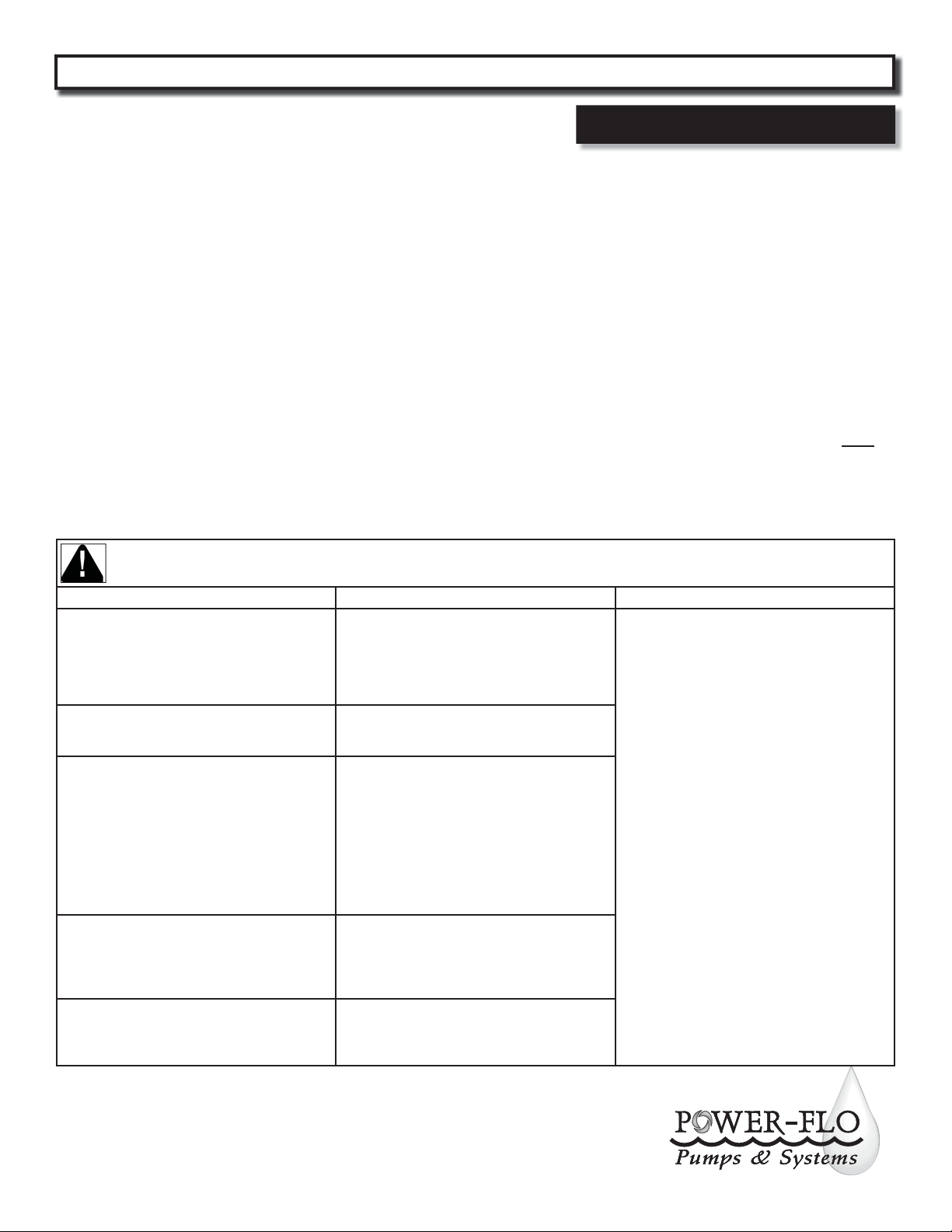
Risk of electric shock. Always disconnect the pump from the power source before handling inspections or repairs.
Symptom Possible Cause(s) Corrective Action
Pump will not run or pump uid
1. Poor electrical connection, blown fuse, tripped
breaker or other interruption of power;
improper power supply
2. Defective motor
3. Insucient liquid level
13. Debris plugging screen and suction intake
1. Check all electrical connections for security.
Have electrician measure current in motor leads,
if current is within ± 20% of locked rotor Amps,
impeller is probably locked. If current is 0,
overload may be tripped. Remove power, allow
pump to cool, then re-check current.
2. Replace pump.
3. Make sure liquid level is above the pump
4. Re-check all sizing calculations to determine
proper pump size.
5. Check discharge line for restrictions, including
ice if line passes through or into cold areas.
6. Remove and examine check valve for proper
installation and freedom of operation
7. Open valve
8. Check impeller for freedom of operation,
security and condition. Clean impeller cavity
and inlet of any obstruction
9. Loosen union slightly to allow trapped air to
escape.
10. Repair xtures as required to eliminate leakage
11. Check pump temperature limits and uid
temperature
12. Replace portion of discharge pipe with exible
connector or tighten existing piping.
13. Check screen and/or suction inlet.
Pump hums but doesn’t run
1. Incorrect low voltage
8. Impeller jammed or loose on shaft, or inlet
plugged
Pump delivers insucient capacity
1. Incorrect low voltage
4. Ecessive inow or pump not properly sized for
application
5. Discharge restricted
6. Check valve partially closed or installed backwards
7. Shut-o valve closed
8. Impeller jammed or loose on shaft, or inlet
plugged
9. Pump may be air locked causing pump not to ow
10. Piping xtures leaking or discharge before the
nozzle
13. Suction restricted
Pump shuts o and turns on independent of
switch, (trips thermal overload protector).
CAUTION! Pump may start unexpectedly.
Disconnect power supply.
1. Incorrect low voltage
4. Ecessive inow or pump not properly sized for
application
8. Impeller jammed or loose on shaft, or inlet
plugged
11. Excessive water temperature
Pump operates noisily or vibrates excessively
2. Worn bearings, motor shaft bent
8. Debris in impeller cavity or broken impeller
12. Piping attachments to building structure too
loose or rigid
NOTE: Power-Flo Pumps & Systems assumes no responsibility for damage or injury due to
disassembly in the eld. Disassembly of the pumps or supplied accessories other than at
Power-Flo Pumps & Systems or its authorized service centers, automatically voids warranty.