Power Innovations MPDU User manual

MNL151
Rev 4.3
Export Classification EAR99

READ THIS MANUAL CAREFULLY
SAVE ALL INSTRUCTIONS
This manual contains important information needed to operate the MPDUTM safely and
efficiently. Please read all instructions carefully before installing or operating equipment.
Keep this manual handy for easy reference.
ELECTRICAL WARNING
Applying information contained in this manual to any other
product, including customized Q-LS systems with
nonstandard specifications, may cause injury.
MPDU™, MPDS™, Q-LS™,Q-LS Uninterruptible Power Quality™, UPQ™, and UPQ-
NetAgent9™are trademarks of Power Innovations International, Inc.
This manual may accompany other instructional addendums about additional
customizations to standard MPDS™systems. Please contact Power Innovations if
additional manuals are needed and have not been received.
Product names mentioned herein may be trademarks and/or registered trademarks of
their respective companies.
Copyright © 2018-2023
Power Innovations International, Inc.; American Fork, UT, USA
All rights reserved

MNL151-4.3 Revision 4/12/2023
Power Innovations—MPDU™User’s Manual i
TABLE OF CONTENTS
TABLE OF CONTENTS ..............................................................................................................................................I
SAFETY ...................................................................................................................................................................... III
SPECIAL INSTRUCTIONS..............................................................................................................................................
III
WARNINGS ..................................................................................................................................................................
III
IMPORTANT SAFETY INSTRUCTIONS ..........................................................................................................................
III
1. INTRODUCTION .....................................................................................................................................................1
1.1 DESCRIPTION ........................................................................................................................................................1
1.2 WTT MPDU Front Panel..................................................................................................................................... 3
1.3 WTT MPDU BACK PANEL .................................................................................................................................4
1.4 TSSC MPDU FRONT PANEL ...............................................................................................................................5
1.5 TSSC MPDU BACK PANEL ............................................................................................................................... 6
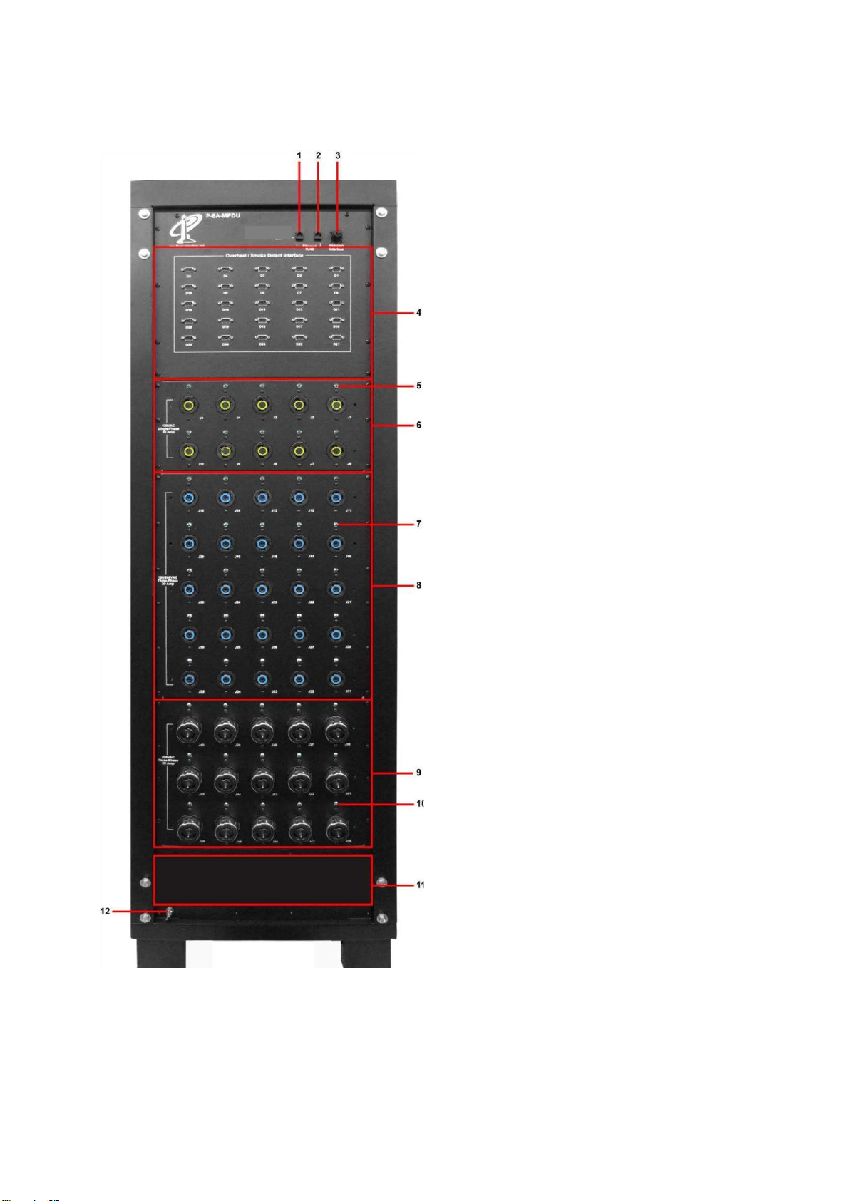
1.6 PTT MPDU FRONT PANEL................................................................................................................................. 7
1.7 PTT MPDU BACK PANEL ................................................................................................................................. 8
1.8 VMT MPDU Front Panel.................................................................................................................................... 9
1.9 VMT MPDU Back Panel............................................................................................................................... 10
1.10 WTT MPDU PROGRAMMABLE LOGIC CONTROLLER (PLC)......................................................................... 11
1.11 TSSC/PTT MPDU PROGRAMMABLE LOGIC CONTROLLER (PLC)................................................................ 12
1.12 VMT MPDU PROGRAMMABLE LOGIC CONTROLLER (PLC)......................................................................... 14
2. INSTALLATION.....................................................................................................................................................16
2.1 UNPACKING THE SYSTEM ..................................................................................................................................16
2.2 CONTENTS OF THE SYSTEM ...............................................................................................................................16
2.3 INSPECTION OF THE SYSTEM.............................................................................................................................. 16
2.4 SITE AND ENVIRONMENT CONSIDERATIONS..................................................................................................... 16
2.5 Q-LS OUTPUT CONNECTIONS ............................................................................................................................17
2.6 MPDU INPUT CONNECTIONS ............................................................................................................................18
2.7 Q-LS / MPDU DATA CONNECTION .................................................................................................................. 20
3. OPERATION ..........................................................................................................................................................21
3.1 PRE-START RE-CHECK .......................................................................................................................................21
3.2 OPERATING PROCEDURE.................................................................................................................................... 21
Startup Procedure................................................................................................................................................... 21
Shutdown Procedure...............................................................................................................................................21
4. TOUCHSCREEN..................................................................................................................................................22
4.1 MPDS™SOFTWARE USER GUIDE.................................................................................................................... 22
5. PROGRAMMABLE LOGIC CONTROLLER (PLC)..................................................................................... 23
5.1 PLC OVERVIEW................................................................................................................................................... 23
5.2 PLC INPUTS .........................................................................................................................................................23
5.3 PLC CONTROL .....................................................................................................................................................24
5.4APPENDIX A.........................................................................................................................................................24
6. PLC SOURCE CODE EXAMPLE ..................................................................................................................... 25
6.1INTRODUCTION ....................................................................................................................................................25
6.2I/OMAPPING........................................................................................................................................................ 26

ii |
6.3SMOKE ALARM TABLE ..........................................................................................................................................27
6.4FLOWCHART………............................................................................................................................................27
APPENDIX A –I/O MAPPING…….. ...................................................................................................................... 38
A.1BLOCK INSTRUCTGIONS FOR VMT...........................................................................................................25
APPENDIX B –WARRANTY ....................................................................................................................... 56
CONTACTING POWER INNOVATIONS …….. ................................................................................................. 57

MNL151-4.3 Revision 4/12/2023
Power Innovations—MPDU™User’s Manual iii
Important SafetyInstructions
This manual contains important instructions that should be followed during installation and for
maintenance of the MPDU™system.
CAUTION
Install the MPDU™system in a temperature-controlled indoor environment where it is clean, dry, and
free of conductive contaminants.
CAUTION
For safety, please ensure that all individual circuit breakers are in the OFF position prior to installing the
MPDU™system to the Q-LS™system. Serious injury or death may result from failure to ensure that
all power connections are OFF.

iv |
This page intentionally left blank.

MNL151-4.3 Revision 4/12/2023
Power Innovations—MPDU™User’s Manual 1
Q-LS
Battery Bank 2
(if used)
Q-LS
Battery Bank 1
Input
Figure 1—MPDS Topology
1. INTRODUCTION
1.1 Description
The Main Power Distribution Unit™(MPDU) is designed with three-phase 120/208 VAC input. The unit supplies
single-phase 120 VAC and three-phase 120/208 VAC output power. The MPDU comes in four varieties with
different power output options: The Weapons Tactical Trainer (WTT), the Training System Support Center (TSSC),
Parts Task Trainer (PTT), and the Virtual Maintenance Trainer (VMT). The MPDU serves as the main source of AC
power into the training device(s). The MPDU monitors the status and distributes power to all equipment requiring AC
power within the training devices.
The MPDU features a user-friendly touchscreen to access data, which is monitored by sophisticated software. The
intelligent monitoring software is easily accessible through the user-friendly touchscreen on the front side of the unit as
well as remotely through a TCP/IP Ethernet connection. Using the software, the user can access real time data and
event history of the unit, as well as data and historical event data from both the MPDU and the attached Q-LS™system.
MPDS Topology
Output
To Facility EPO
Q-LS
UPQ

2 |
Figure 2—MPDS VMT Block Diagram

MNL151-4.3 Revision 4/12/2023
Power Innovations—MPDU™User’s Manual 3
1.2 WTT MPDU Front Panel
1. Alarm Speaker: PLC controlled.
2. EPO Switch: Emergency Power OFF.
3. Touchscreen: Gives user access to MPDS™
status.
4. MPDU Total Hours: Total run time, in hours, of
the MPDU when the main input breaker (#10) is
ON.
5. MPDU Main Power Status Indicator LED:
Indicates the power input status of the MPDU. If
the LED is illuminated, the MPDU is receiving
input power, which means the main input breaker
(#10) is ON.
6. Trainer Power ON / OFF Button: Turns the
trainer power ON / OFF.
7. 30 Amp 1Ø Output Circuit Breakers: Activate or
deactivate 1Ø system output power.
8. 30 Amp 3Ø Output Circuit Breakers: Activate or
de-activate system 3Ø output power.
9. 50 Amp 3Ø Output Circuit Breakers: Activate or
de-activate system 3Ø output power.
10. 500A 3Ø MPDU Main Breaker with shunt trip:
Turns the MPDU output power ON / OFF.
11. 30 Amp-3Ø Power Distribution Indicator LEDs:
Indicate the power output status of the
connectors. If an LED is illuminated, the
receptacle is live.
12. 30 Amp 1Ø Power Distribution Indicator LEDs:
Indicate the power output status of the
connectors. If an LED is illuminated, the
receptacle is live.
13. EPO Delay Button: Activates EPO Delay.
14. MPDU Logic Power Breaker: Turns the MPDU
Logic ON/OFF.
15. USB Maintenance: Connects external equipment
to internal PC for user maintenance.
16. Ethernet Maintenance: Connects external
equipment to internal MPDU intranet.
17. 50 Amp 3Ø Power Distribution Indicator LEDs:
Indicate the power output status of the
connectors. If an LED is illuminated, the
receptacle is live

4 |
1.3 WTTMPDUBackPanel
1. Q-LS Communication Link: Connects the
MPDU to the Q-LS system.
2. RJ-45 Ethernet Port: Connects the MPDU
to the local network.
3. CPC Connector: TSS EPO Interface
4. DB-9 Connector: Connects temperature,
smoke, and other sensors to the MPDU’s
internal PLC Logic.
5. 30 Amp 1Ø Power Distribution Indicator
LEDs: Indicate the power output status of
the connectors. If an LED is illuminated,
the receptacle is live.
6. 30 Amp 1Ø Power Output Receptacles:
Connect the load to 30 Amp –120VAC
output power via L5-30 connectors.
7. 30 Amp-3Ø Power Distribution Indicator
LEDs: Indicate the power output status of
the connectors. If an LED is illuminated,
the receptacle is live.
8. 30 Amp-3Ø Power Output Receptacles:
Connect the load to 30 Amp –120/208
VAC output power via L21-30 connectors.
9. 50 Amp-3Ø Power Output Receptacles:
Connect the load to 50 Amp –208 VAC
output power via CS-8369 connectors.
10.50 Amp-3Ø Power Distribution Indicator
LEDs: Indicate the power output status of
the connectors. If an LED is illuminated,
the receptacle is live.
11.Input Gland Plate: Removable to allow
input and ground wire installation.
12.Grounding Studs/Plate: Single or multiple
(optional) ground attachment points allow
the grounding of other equipment to the
MPDU.

MNL151-4.3 Revision 4/12/2023
Power Innovations—MPDU™User’s Manual 5
1.4 TSSCMPDUFrontPanel
1. Alarm Speaker: PLC controlled.
2. EPO Switch: Emergency Power OFF.
3. Touchscreen: Gives user access to MPDS status.
4. MPDU Total Hours: Total runtime in hours of
MPDU with main input breaker (11) ON.
5. MPDU Main Power Status Indicator LED:
Indicates the power status of the MPDU. If the
LED is illuminated, the MPDU is receiving
input power and the main input breaker (11) is
ON.
6. Trainer power ON/OFF button: Turns the trainer
power ON or OFF.
7. 120V AC Single-phase 20A Circuit Breakers:
Switch breakers to turn output ON or OFF.
8. 120/208V AC Three-phase 30A Y Circuit
Breakers: Switch breakers to turn output ON
or OFF.
9. 120/208V AC Three-phase 30A Y Circuit
Breakers (second panel): Switch breakers to
turn output ON or OFF.
10. 208V AC Three-phase 30A Δ Circuit Breakers:
Switch breakers to turn output ON or OFF.
11. MPDU Main Input Breaker: Turns the MPDU
output ON or OFF.
12. 208V AC Three-phase 30A ΔIndicator LED:
Indicator LED illuminates if power is ON to
the output receptacle.
13. 120/208V AC Three-phase 30A Y Indicator
LED:(second panel) Indicator LED illuminates
if power is ON to the output receptacle.
14. 120/208V AC Three-phase 30A Y Indicator
LED: Illuminates if power is
ON to the output receptacle.
15. 120V AC Single-phase 20A Indicator LED:
Illuminates if power is ON to the output
receptacle.
16. EPO Delay Button: Activates EPO delay.
17. MPDU Logic Power Breaker: Turns the
MPDU Logic module ON or OFF.
18. USBMaintenancePorts:Allows the
connection of external USB equipment for PC
maintenance.
19. CPU Control Button: Allows user to cycle
power or reset the PC.
20. Ethernet Maintenance: Allows the connection
of an RJ45 Ethernet cable to connect external
devices to the MPDU.

6 |
1.5 TSSCMPDUBackPanel
1. CPC Connector: TSS EPO Interface.
2. RJ45 Ethernet Port: Connects the MPDU
to the local network.
3. Q-LS Communication Link: Connects the
MPDU to the Q-LS system.
4. DB-9 Connectors: Connects temperature,
smoke, and other sensors to the MPDU
internal PLC logic.
5. 120 VAC Single-phase 20 Amp
Receptacles: Connect the load to 20A-120
V AC output power via L5-20 connectors.
6. 120/208 VAC Three-phase30 Amp Y
Receptacles: Connect the load to 30A-
120/208 V Y AC output power via L21-
30 connectors.
7. 120/208 VAC Three-phase 30 Amp Y
(second panel) Receptacles: Connect the
load to 30 Amp 120/208 V Y AC output
power via L21-30 connectors.
8. 208 VAC Three-phase 30 Amp Δ
Receptacles: Connect the load to 30 Amp
208 V ΔAC output power via L15-30
connectors.
9. Input Gland Plate: Removable to allow
input and ground wire installation.
10. Grounding Studs/Plate: Single or multiple
(optional) ground attachment points allow
the grounding of other equipment to the
MPDU.
11. 208 VAC Three-phase 30 Amp ΔIndicator
LED: Illuminates if the receptacle is live.
12. 120/208 VAC Three-phase 30 Amp Y
(second panel) Indicator LED: Illuminates
if the receptacle is live.
13. 120/208 VAC Three-phase 30 Amp Y
Indicator LED: Illuminates if the
receptacle is live.
14. 120 VAC Single-phase 20 Amp Indicator
LED: Illuminates if the receptacle is live.

MNL151-4.3 Revision 4/12/2023
Power Innovations—MPDU™User’s Manual 7
1.6 PTTMPDUFrontPanel
1. Alarm Speaker: PLC controlled.
2. EPO Switch: Emergency Power Off.
3. Touchscreen: Gives user access to MPDS
status.
4. MPDU Total Hours: Total runtime in hours
of MPDU with main input breaker (11) ON.
5. MPDU Main Power Status Indicator LED:
Indicates the power status of the MPDU. If
the LED is illuminated, the MPDU is
receiving input power and the main input
breaker (11) is ON.
6. Trainer power ON/OFF button: Turns the
trainer power ON or OFF.
7. 120 VAC Single-phase 20 Amp Circuit
Breakers: Switch breakers to turn output ON
or OFF.
8. 120 VAC Single-phase 30 Amp Circuit
Breakers: Switch breakers to turn output
ON or OFF.
9. 120/208 VAC Three-phase 30 Amp Circuit
Breakers: Switch breakers to turn output
ON or OFF.
10. 208 VAC Three-phase 50 Amp Circuit
Breakers: Switch breakers to turn output ON
or OFF.
11. MPDU Main Input Breaker: Turns the
MPDU output ON or OFF.
12. 208 VAC Three-phase 50 Amp Indicator
LED: Indicator LED illuminates if power is
ON to the output receptacle.
13. 120/208 VAC Three-phase 30Amp Indicator
LED: Indicator LED illuminates if power is
ON to the output receptacle.
14. 120 VAC Single-phase 30 Amp Indicator
LED: Illuminates if power is ON to the
output receptacle.
15. 120 VAC Single-phase 20 Amp Indicator
LED: Indicator LED illuminates if power is
ON to the output receptacle.
16. EPO Delay Button: Activates EPO delay.
17. MPDU Logic Power Breaker: Turns the
MPDU Logic module ON or OFF.
18. USB Maintenance Ports: Allows the
connection of external USB equipment for
PC maintenance.
19. CPU Control Button: Allows user to cycle
power or reset the PC.
20. EthernetMaintenance:AllowsRJ45 Ethernet
cable to connect external devices to the
MPDU.

8 |
1.7 PTTMPDUBackPanel
1. CPC Connector: TSS EPO Interface.
2. RJ45 Ethernet Port: Connects the MPDU to
the local network.
3. Q-LS Communication Link: Connects the
MPDU to the Q-LS system.
4. DB-9 Connectors: Connects temperature,
smoke, and other sensors to the MPDU
internal PLC logic.
5. 120 V AC Single-phase 20 Amp
Receptacles:
Connect the load to 20A-120 VAC output
power via L5-20 connectors.
6. 120 V AC Single-phase 30 Amp
Receptacles:
Connect the load to 30 Amp 120 VAC
output power via L5-30 connectors.
7. 120/208 VACThree-phase30 Amp
Receptacles. Connect the load to 30 Amp
120/208 VAC output power via L21-30
connectors.
8. 208 VAC Three-phase 50 Amp
Receptacles: Connect the load to 50 A-208
VAC output power via CS-8369
connectors.
9. Input Gland Plate: Remove to allow input
and ground wire installation.
10. Grounding Studs/Plate: Single or multiple
(optional) ground attachment points allow the
grounding of other equipment to the MPDU.
11. 208 VAC Three-phase 50 Amp Indicator
LED: Illuminates if the receptacle is live.
12. 120/208 VAC Three-phase 30 Amp Indicator
LED: Illuminates if the receptacle is live.
13. 120 VAC single-phase 30 Amp Indicator
LED: Illuminates if the receptacle is live.
14. 120 VAC Single-phase 20 Amp Indicator
LED: Illuminates if the receptacle is live.

MNL151-4.3 Revision 4/12/2023
Power Innovations—MPDU™User’s Manual 9
2
1
3
4
5
9
10
12
13
8
6
11
7
1.8 VMTMPDUFrontPanel
1. Alarm Speaker: PLC controlled.
2. EPO Switch: Emergency Power Off.
3. Touchscreen: Gives user access to MPDS
status.
4. MPDU Total Hours: Total runtime in hours
of MPDU with main input breaker (8) ON.
5. MPDU Status Indicator LED: Indicates the
power status of the MPDU. If the LED is
illuminated, the PLC has completed booting
up.
6. 120 VAC Single-phase 15 Amp Circuit
Breakers: Switch breakers to turn output ON
or OFF.
7. MPDU Power Status Indicator LED:
Indicates the power status of the MPDU. If
the LED is illuminated, the MPDU is
receiving input power and the main input
breaker is ON.
8. MPDU Main Input Breaker: Turns the
MPDU output ON or OFF.
9. MPDU Power Indicator LED: Indicates the
MPDU has been power on with the main
input breaker ON.
10. MPDU Logic Power Breaker: Turns the
MPDU Logic module ON or OFF.
11. USB Maintenance Ports: Allows the
connection of external USB equipment for
PC maintenance.
12. CPU Reset Button: Allows user to cycle
power or reset the PC.
13. Ethernet Maintenance:Allows RJ45
Ethernet cable to connect external devices
to the MPDU.

10 |
6
7
3
1
2
4
5
8
1.9 VMTMPDUBackPanel
1. RJ45 Ethernet Q-LS Comm. Link: Connects
the MPDU to the Q-LS.
2. RJ45 Ethernet Network Comm.: Connects
the MPDU to the local network.
3. Q-LS EPO Interface.
4. J3 EPO Out: Connects temperature, smoke,
and other sensors to the MPDU internal
PLC logic.
5. J2 EPO In Connection:
Connects temperature, smoke, and other
sensors to the MPDU internal PLC logic.
6. 120 VAC Single-phase 15 Amp
Receptacles:
Connect the load to 15 Amp 120 VAC
output power via L5-15R connectors.
7. E1 multiple ground attachment that allows
the grounding of other equipment to the
MPDU.
8. Key Switch: J1 Control Key that connects to
the “Trainer Power ON/OFF” key switch on
the front of the Support Equipment Cabinet.

MNL151-4.3 Revision 4/12/2023
Power Innovations—MPDU™User’s Manual 11
1.10 WTTProgrammable LogicController(PLC)
1. PLC 120 VAC Bus.
2. EPO Relay.
3. Ethernet Hub for Digital communications between components.
4. PLC Input Module: High-density 32-port breakout module for smoke and heat detect.
5. Test Switch: Test module switch (user programmable for testing).
6. I/O Modules: 32-bit high-density input modules for smoke/heat detect boards.
7. I/O Module: I/O module used for EPO alarm speaker and trainer power ON/OFF switch (see 4 above).
8. I/O Modules: I/O Modules used for relay control.
9. PLC Brain/Controller: Runs user programmed strategies (Ethernet accessible).
10. PLC Power Supply: +5 V power supply with ON/OFF switch.
11. Touchscreen and embedded PC.

12 |
1.11 TSSC/PTTMPDUProgrammable LogicController(PLC)
MPDU PLC Right Side
1. PLC Power Supply: +5 V power supply with ON/OFF switch.
2. Ethernet Hub for Digital communications between components.
3. Input High Density Breakout Board.
4. Touchscreen and embedded PC.
5. PLC Brain/Controller: Runs user programmed strategies (Ethernet accessible).
6. I/O Modules: I/O modules used for relay control.
7. HD Module: 32-bit high density input module for the HD breakout board.
8. I/O Modules: 32-bit high density input modules for smoke/heat detector boards.
9. PLC 120 V Bus.

MNL151-4.3 Revision 4/12/2023
Power Innovations—MPDU™User’s Manual 13
MPDU PLC Left Side
1. PLC Smoke Input Module: 32-bit high density breakout board for smoke detectors.
2. Test Switch: Test module switch (user programmable for testing).
3. PLC Heat Input Module: 32-bit high density breakout board for heat detectors.
4. EPO Relay
5. Heat/Smoke Positive Power Bus: Distributes power connections for heat/smoke modules.
6. Heat/Smoke Negative Power Bus: Distributes power connections for heat/smoke modules.
7. 24 V Heat/Smoke Power Supply: Provides power for heat/smoke input modules.

14 |
1
2
3
4
5
1.12 VMTMPDUProgrammable LogicController(PLC)
MPDU PLC Left Side
1. 24 V power supply.
2. 12 V power supply.
3. PC module.
4. Touchscreen.
5. Terminal block.
Other manuals for MPDU
1
Table of contents
Other Power Innovations Power Distribution Unit manuals
Popular Power Distribution Unit manuals by other brands

Ground Zero
Ground Zero GZTC 1.0FX owner's manual

ATEN
ATEN PE5340SL user manual

CyberPower
CyberPower PowerPanel Business Edition installation guide

Geist
Geist RCX instruction manual

Konig
Konig CMP-POWG21 manual

LIGHTNING PROTECTION INTERNATIONAL PTY LTD
LIGHTNING PROTECTION INTERNATIONAL PTY LTD Stormaster ESE installation manual