Power Lift CS60EVO User manual

Owners Copy: SAVE THESE INSTRUCTIONS for future reference
CS60EVO
Sectional Garage Door Opener
Installation an Operating Instructions
This manual contains IMPORTANT SAFETY information
DO NOT PROCEED WITH THE INSTALLATION BEFORE READING THOROUGHLY
www.chamberlain iy.com.au
www.chamberlain iy.co.nz

1
CONTENTS PAGE
SAFETY I STRUCTIO S . . . . . . . . . . .1
BEFORE YOU BEGI . . . . . . . . . . . . . .2
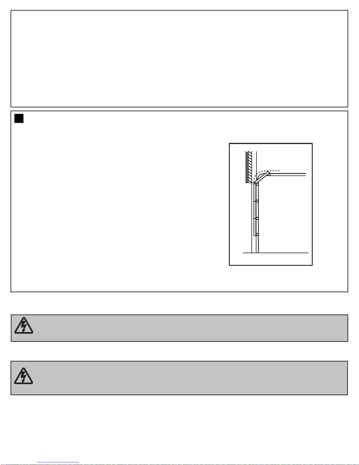
DOORTYPES ....................2
CARTO I VE TORY . . . . . . . . . . . . .3
RAILSIZES ......................3
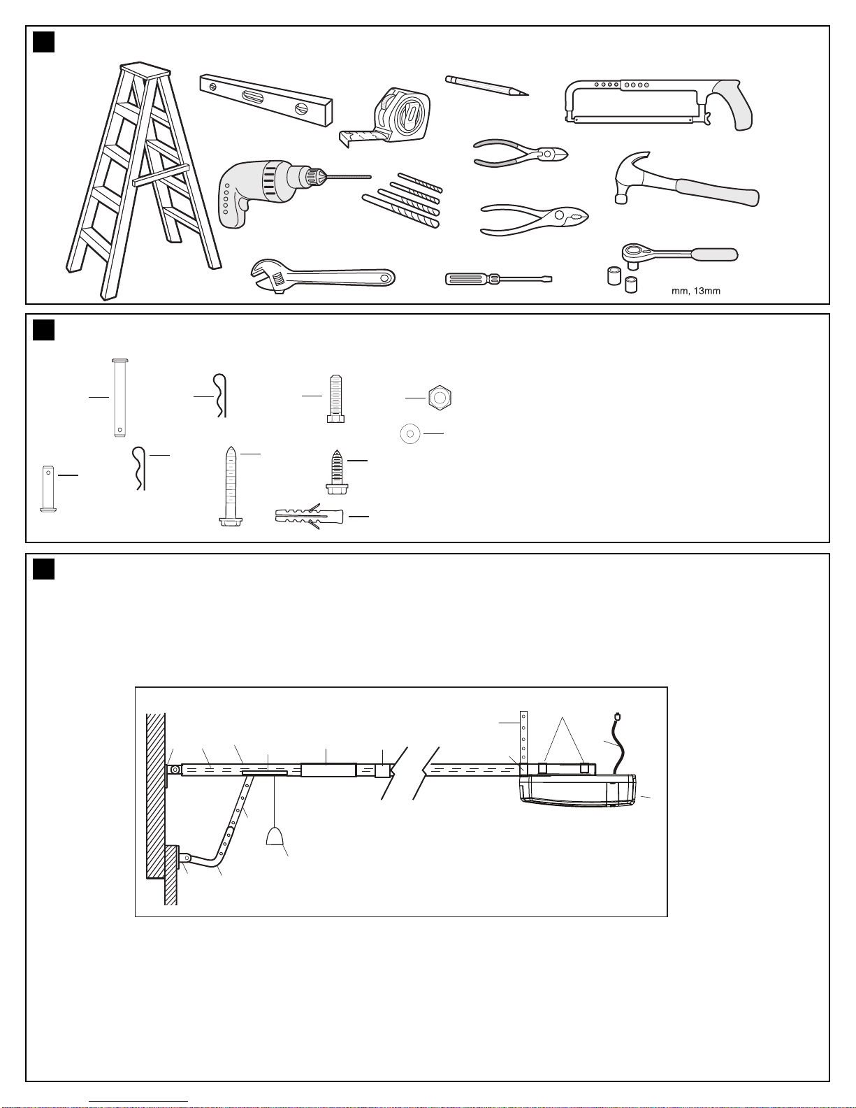
TOOLS REQUIRED . . . . . . . . . . . . . . . .4
HARDWARE PROVIDED . . . . . . . . . . . .4
COMPLETED I STALLATIO . . . . . . . .4
CO TROLPA EL .................5
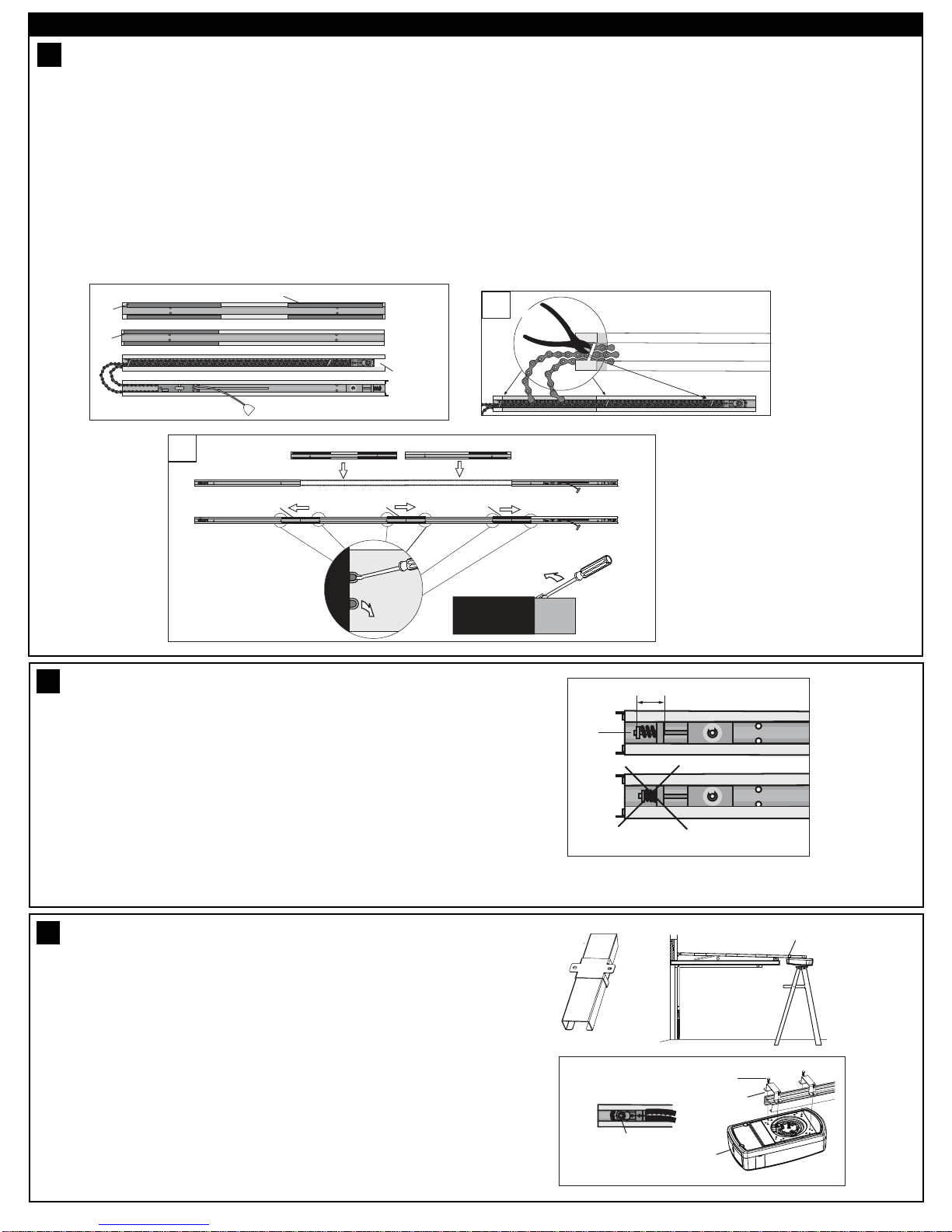
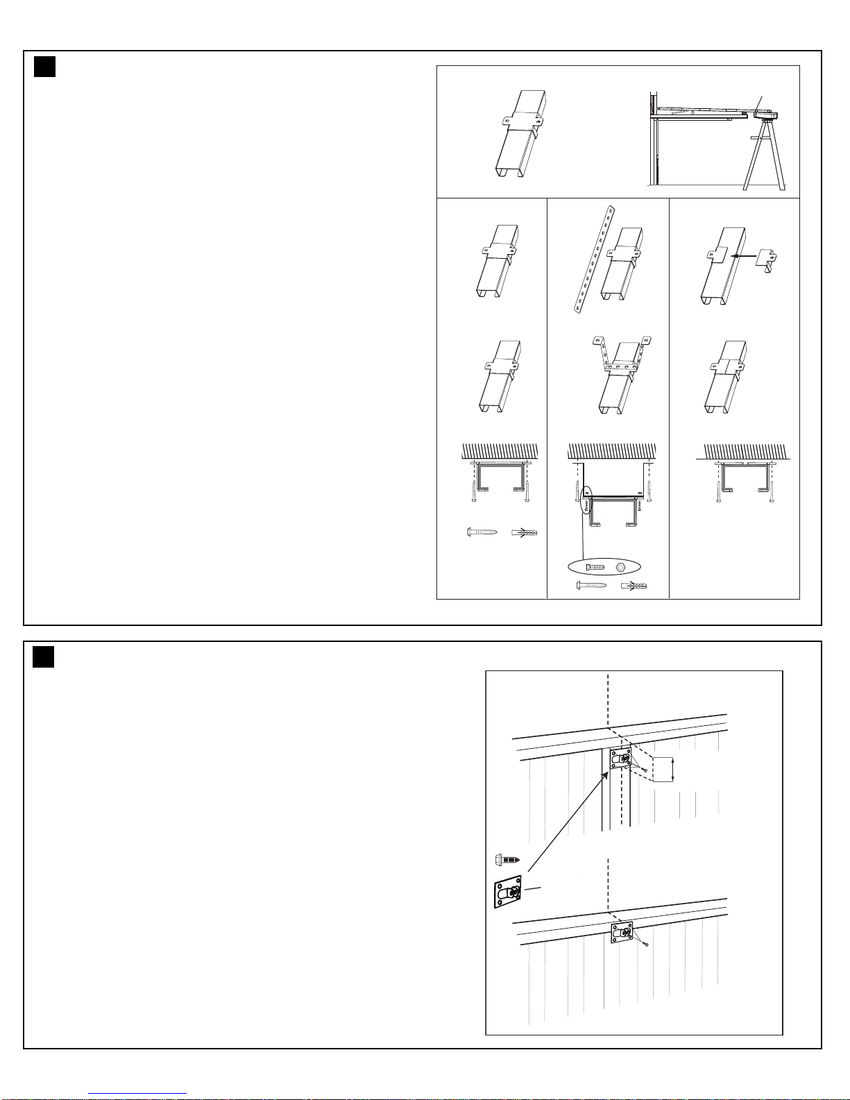
ASSEMBLY ......................6
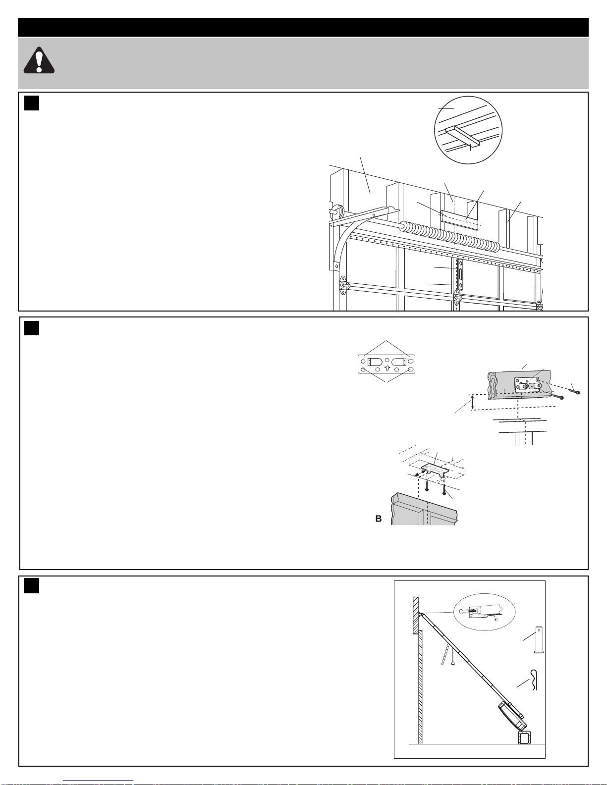
I STALLATIO . . . . . . . . . . . . . . . . .7-10
OPERATE THE MA UAL RELEASE . .10
ADJUSTME T . . . . . . . . . . . . . . . .11-12
I STALL THE PROTECTOR
SYSTEM (OPTIO AL) . . . . . . . . . . . . .13
TIMER TO CLOSE . . . . . . . . . . . . . . . .14
I STALL WAR I G LABELS . . . . . . .15
PARTIAL OPE I G FEATURE . . . . . .15
WIRELESS PROGRAMMI G . . . . . . .16
USI G YOUR OPE ER . . . . . . . . . . .17
CARE OF YOUR OPE ER . . . . . . . . .17
REPLACE BATTERIES I
REMOTE .......................17
ACCESSORIES ..................18
TROUBLESHOOTI G . . . . . . . . . . 19-20
SPECIFICATIO S . . . . . . . . . . . . . . . .21
WARRA TY.....................22
Warning: If your garage has no service entrance door, a E1702M outside quick release must be installed. This
accessory allows manual operation of the garage door from outside in case of power failure.
The rotector SystemTM must be used for all installations
where the closing force as measured on the bottom of the
door is over 400 N (40 kgf). Excessive force will interfere with
the proper operation of the Safety Reverse System or damage
the garage door.
SPECIAL NO E: Chamberlain strongly recommends that
he Protector System M be installed on all garage door
openers.
After installation, ensure that the parts of the door do not
extend over public footpaths or roads.
Install the wireless wall control (or any additional wall control) in
a location where the garage door is visible, at a height of at
least 1.5 m and out of the reach of children. Do not allow
children to operate push button(s) or transmitter(s). Serious
personal injury from a closing garage door may result from
misuse of the opener.
ermanently fasten the Warning Labels in rominent laces,
adjacent to Wall Controls and on manual release mechanism as
a reminder of safe operating procedures.
Activate opener only when the door is in full view, free of
obstructions and the opener is properly adjusted. No one
should enter or leave the garage while the door is in motion.
Automatic Door- The door may operate unexpectedly, therefore
do not allow anything to stay in the path of the door.
Do not allow children to play near the door, or with door
controls. Keep remotes away from children.
Disconnect electric power to the garage door opener before
making repairs or removing covers.
If the supply cord is damaged, it must be replaced by the
manufacturer, its service agent or similarly qualified persons in
order to avoid hazard.
This opener should not be installed in a damp or wet space
exposed to weather.
To avoid damage to very light doors (such as fibreglass,
aluminium or steel doors), an appropriate reinforcement should
be added. To do so, contact the door manufacturer.
SAVE THESE INSTRUCTIONS
•Failureto comply withthefollowing instructions may resultin seriouspersonalinjury orproperty amage.
• Rea an follow all instructions carefully.
• The garage oor opener is esigne an teste to offer safe service, provi e it is installe an operate in
strict accor ance with the instructions in this manual.
These safety alert symbols mean WARNING : A possible risk to personal safety or property
amage exists.
Keep garage door balanced.Do not let the garage door
opener compensate for a binding or sticking garage door.
Sticking, binding or unbalanced doors must be repaired
before installing this opener.
Do not wear rings, watches or loose clothing while
installing or servicing a garage door opener. Wear gloves,
safety goggles and suitable protective clothing where
appropriate.
Frequently examine the door installation, in particular
cable, springs and mountings for signs of wear, damage or
imbalance. Do not use if repair or adjustment is needed
since springs and hardware are under extreme tension
and a fault can cause serious personal injury.
To avoid serious personal injury from entanglement,
remove all ropes, chains and locks connected to the
garage door before installing the door opener.
Installation and wiring must be in compliance with your
local building and electrical codes.
The safety reverse system test is very important. Your
garage door MUST reverse on contact with a 40 mm
obstacle placed on the floor. Failure to properly adjust the
opener may result in serious personal injury from a closing
garage door. Repeat the test once a month and make
any necessary adjustments.
This appliance is not intended for use by persons
(including children) with reduced physical, sensory or
mental capabilities, or lack of experience and knowledge,
unless they have been given supervision or instruction
concerning use of the appliance by a person responsible
for their safety.
Use the Manual Release only for the seperation of the
carriage from the drive and - if possible - O LY with the
door closed. Do not use the red handle to push the door
up or pull it down. Operation of the emergency release can
lead to uncontrolled movements of the door, if springs are
weak or broken or if the door is unbalanced. Mount the
release handle of the emergency release at a height less
than 1.8 m from the floor.
START BY READING THESE IM ORTANT SAFETY INSTRUCTIONS
WARNING!

2
BEFORE YOU BEGIN:
1. Look at the wall and ceiling above the garage door. (The opener and header bracket must be securely fastened to structural
supports.)
2. Do you have a finished ceiling in your garage? If so, a support bracket and additional fastening hardware (not supplied) may
be required.
3. Do you have an access door in addition to the garage door? If not, model E1702M Outside Quick Release Accessory is
required. This accessory allows manual operation of the garage door from outside in case of power failure.
4. Complete the following test to make sure your garage door is balanced and is not sticking or binding:
• Lift the door about halfway. Release the door. If balanced, it should stay in place, supported entirely by its springs.
• Raise and lower the door to see if there is any binding or sticking, 20 kgf is the absolute maximum allowable force to raise or
lower the door in any position. If your door binds, sticks, or is out of balance, call a trained door technician.
DOOR TY ES
Sectional Door with curved track (MAX. door height 2.2 m)
PowerLift - CS60EVO:
To suit spring balanced Sectional doors up to 12.0 m2.
1
Electrical Connection
A 240 V General Purpose Outlet (GPO) ie. Power Point must be available in close proximity to the powerhead.
his fitting is not part of the Opener hardware and must be supplied by the consumer.
In the event of a power outage or the unit being disconnected from the power source, the door MUS be operated and
supervised so that it completes a full UP and DOWN cycle with no obstructions in place to ensure that the unit
automatically checks that the safety force settings are correct.

1245
6789
10
11
3
14 13 15
12
114A3361
ForService Call
InstallationDate
132A2900
RISKOF ENTRAPMENT
RepeatSafety Reverse Test monthly Door
mustreverse on contact with a 40mm obstacle
placedon the floor Make necessary adjustments
AUTOMATICDRIVE:
Keepaway from the area of the door since it may
operateunexpectedly
EMERGENCYRELEASE:
Torelease pull down firmly on the red handle
OwnersCopy:SAVETHESEINSTRUCTIONSforfuturereference
CS60EVO
Sectional Garage Door Opener
Installation and Operating Instructions
Thismanual contains IMPORTANT SAFETY information
DONOT PROCEED WITH THE INSTALLATION BEFORE READING THOROUGHLY
N2966N2966N2966N2966
w w w .chamberlaindiy .com.au
ww w .chamberlaindiy .co.nz
CARTON INVENTORY
(1) Opener
(2) Hand held transmitter x 1
(3) Remote control visor mount
(4) Curved door arm
(5) Hanging bracket (2)
(6) Rail bracket
(7) Header bracket
(8) Door bracket
(9) Hardware bag
(10) Rail assembly
(11) C-Rail bracket (2)
(12) Centre Rail Bracket
(13) Manual
(14 Warning labels
(15) Warranty card
Your garage door opener and rail are packed in a single carton. The PowerLift CS60EVO opener cartons contain the
opener, the rail, its fitting hardware and accessories.
2
RAIL DIMENSIONS
3
NOTE: The Ceiling ixing Point is measured back from the lintel (see item 1 to 7 of “completed installation”). Also
allow 400 mm back from the fixing point for installation of the powerhead (item 7 to 9 of “completed installation”).
3
DOOR HEIGHT:
Sectional Doors BELT & RAIL
PART UMBER: RAIL LE GTH: CEILI G FIXI G
POI TS:
Up to 2.2 m 8422 CR5 3000 mm segmented 2840 mm

4
4
12345
78
9
10
11
6
12
13
14
15
(1) Header bracket
(2) Belt
(3) Rail
(4) Trolley
(5) Rail connecting piece
(6) Rail bracket
(7) Hanging bracket
(8) Power cord
(9) Opener
(10) Manual release rope & handle
(11) Straight door arm
(12) Curved door arm
(13) Door bracket
(14) C-Rail brackets
(15) Centre rail bracket
As you proceed with the assembly, installation and adjustment procedures in this manual, you may find it helpful to
refer back to this illustration of a completed installation.
COM LETED INSTALLATION
10 (4x)
9 (8x)
8 (4x)
7 (1x)
6 (1x)
1 (1x) 2 (1x) 3 (4x) 4 (4x)
5 (4x)
HARDWARE ROVIDED (1) Clevis pin 80 mm
(2) R clip
(3) Hexagonal head screw
(4) ut M8
(5) Flat washer M8
(6) Clevis Pin
(7) R clip
(8) Screw ST6 x 50 mm
(9) Screw ST6,3 x 18 mm
(10) Wallplug 8mm
Drill Bits
10
TOOLS REQUIRED
4
5
6

30 V DC
+ -
01 2234567
UP
DOWN
PROG
LEARN
(YELLOW)
INDICATOR
LED
12
3
4
5
6
7
1.External Accessory Power: 30 Vdc 50 mA available for universal receiver (not active in Low standby mode).
2. Terminal Block: used for external accessories (see chart below).
3. UP Button: used for initial programming, to drive the door UP, and for displaying Diagnostic Code - Digit 1.
4. PROG Button: used to program door limits, and other features.
5. DOWN Button: used for initial programming, to drive the door DOWN, and for displaying Diagnostic Code - Digit 2.
6. LEARN Button: used to program remote controls and learn the forces manually.
7. Indicator LED: used to indicate various programming modes.
No Function Colour Polarity Comment
0E-Serial port Green +ve Serial Communication Input
1Push button Red +ve Dry Contact input for push button wired wall controls
2 Ground White -ve Common terminal for push button
2Ground White -ve Common terminal for IR Beams
3IR Sensor Gray +ve Merlin IR Beam Input: (pulsing type only)
4Door-in-door Green +ve For Door in Door dry contact sensor: (4&5 are normally linked)
5Door-in-door Green -ve Common terminal for Door in Door sensor
6Flasher Black +ve Flashing light output: (24 Vdc 150 mA) while door is in motion
7Flasher White -ve Flashing light output: negative terminal
CONTROL ANEL (located under the cover at the rear of the opener)
5
7

ASSEMBLY SECTION
6
37 - 41 mm
1
TIGHTEN THE BELT
Note: The spring must be able to compress and bounce
during operation. Final tensioning can be performed after
installation if necessary. Over tightening the belt may
overload the system and cause excessive wear.
1.Tension the belt by adjusting the nut (1), on the pulley
assembly, clockwise until the spring is engaged.
2.Continue tightening to compress the spring and remove all the
slack in the belt. DO NOT OVERTIGHTEN but ensure belt is
firm.
3.37-41 mm as indicated in the diagram is normal.
3
4
5
2
A
1
1.Slide the RAIL BRACKET (1) onto the powerhead end of the
rail (A) around 200 mm.
2.Position the rail drive spocket (2) over the opener motor shaft
(3) and push down to install.
3.Secure the rail on the opener with two C-Rail brackets (4) and
the screws (5).
This completes the assembly of the door opener to the rail.
FASTEN RAIL TO O ENER
9
10
The segmented rail is largely preassembled and consists of 4 parts. The carriage, push rod, release handle, the guide pulley
and the lintel bracket with belt tensioner are in the front part (A). The seating for the drive shaft and the sprocket are in the
rear part (B). Hardware items are placed in the rails during transportation - remove these. Lay the front and rear rail sections
one behind the other.
1. Remove cable ties that secure the belt.
2. Pull apart the two rail sections completely in order to create a gap for the middle sections (C & D). This rail is designed in such
away so as to easily add the middle section. Slide the 2 connecting pieces (E) over the seams of the rail sections up to the
markings. To secure the connecting pieces, bend the sheet metal lugs outwards with a suitable tool. The assembly of the rail is
complete.
ASSEMBLING THE 4 IECE SEGMENTED RAIL
8
A
B
C
D
E
E
E
X
1.
A
B
CD
EEE
1
2

7
Wear protective goggles when working overhead to protect your eyes from injury.
Disengage all existing garage door locks to avoid damage to the garage door.
o avoid serious personal injury from entanglement, remove all ropes connected to the garage door before
installing the opener.
INSTALLATION SECTION
Header Wall
2
Level
(optional)
1
3
Structural
Supports
OPTIONAL
CEILING
MOUNT
FOR
HEADER
BRACKET
Unfinished
Ceiling
4
2
The header bracket must be rigidly fastened to a
structural support of the garage. Reinforce the wall or
ceiling with a 40 mm (1-1/2") board if necessary. Failure
to comply may result in improper operation of safety
reverse system.
You can attach the header bracket either to the header wall
(1) or to the ceiling (3). ollow the instructions which will
work best for your particular requirements.
With the door closed, mark the vertical centre line (2) of the
garage door. Extend line onto header wall above the door.
Open door to highest point of travel. Draw an intersecting
horizontal line (4) on header wall at least 50 mm above high
point to provide travel clearance for top edge of door.
2
50 mm
3
1
4
A
150 mm
(6")
12
3
5
5
(50 to 200 mm depending on door type)
INSTALL THE HEADER BRACKET
HEADER BRACKET OSITIONING
1
2
Attach the Rail to the Header Bracket
• Position the assembled opener on the garage floor below the
header bracket. Use foam packing material as a protective
base.
NOTE: If the door spring is in the way youʼll need help.
Have someone hold the opener securely on a temporary
support to allow the rail to clear the spring.
• Position the rail bracket against the header bracket.
• Align the bracket holes and secure with the 80 mm clevis pin
and “R” clip (1) and (2).
ATTACH RAIL TO HEADER BRACKET
11
12
13
NOTE: Refer to vertical centre and horizontal lines created in
the previous section for proper placement of header bracket.
A.Wall mount: centre the header bracket (1) on the vertical centre
line (2) with the bottom edge of the header bracket on the
horizontal line (4) (with the arrow pointing toward the ceiling).
Drill and secure the Header Bracket using the most suitable
variation of holes (5). If using the wood screws provided, uses a
4.5 mm pilot drill. If securing to a metal fixture, self tapping “tek”
screws may be more suitable.
B.Ceiling mount: extend vertical centre line (2) onto the ceiling.
Centre the header bracket (1) on the vertical mark no more than
150 mm (6") from the wall. Make sure the arrow is pointing
toward the opener. Drill and secure the Header Bracket using
the most suitable variation of holes (5). If using the wood screws
provided, uses a 4.5 mm pilot drill. If securing to a metal fixture,
self tapping “tek” screws may be more suitable. or concrete
ceiling fixtures, 8 mm wall plugs are provided.

8
Rail
Door 50 mm spacer should
be used to determine
the correct mounting
position
Header
Bracket 50 mm (2”)
above the highest
point of travel
OSITION THE O ENER
SECTIONAL DOOR
You will need a 50 mm piece of timber or similar spacer to gauge the distance between door and rail.
1.Raise the opener onto support.
2.Open the door completely, place a 50 mm spacer between the door and the rail (as shown).
3.The final positioning of the rail should be relatively parallel to the horizontal door panels.
14
Disengage the trolley mechanism (see section “Operating the manual release”) and slide it back towards the powerhead.
Secure the hanging push arm up into the rail assembly temporarily using tape or rope, to avoid a hazard.

9
X
A
fig.1
fig.2 fig.3 fig.4
HANG THE O ENER
100-300 mm
1
A
The door bracket must be securely fastened to the frame
or a structural support on the door.
ounting position for Sectional Doors with structural
centre support
1.Align the bracket on the centre line, measure down 100-
300 mm from the door top edge.
2.Secure the bracket in this position, using the most
suitable variation of holes available.
ounting Position for Sectional Doors with structural
Top Rail
1.Align the door bracket on the centre line on a structural
Top edge of the door.
2.Secure the bracket in this position, using the most
suitable variation of holes available.
FASTEN DOOR BRACKET
15
16
The opener must be securely fastened to a sound
structural support above the opener.
1.Postion the opener as in the previous step. Check the rail
is centred over the door.
Ensure the rail brackets (fig.1) is on the Powerhead end of
the rail in a position as close to the opener as possible (X).
2.If mounting directly onto the ceiling, (fig.2) screw the
bracket directly into a structural support on the ceiling.
3.If hanging the opener below the ceiling, (fig.3) bend the
hanging brackets provided, and secure to both the ceiling
and the rail bracket.
4.If installing a segmented rail, a centre rail bracket is
supplied for installation in the mid position of the rail.
Simply slip both halves over the top of the rail (fig.4), and
secure to the ceiling, either directly or with hanging strips.
5.Check the opener is securely centred over the door.
Remove the 50 mm spacer, and any other assembly
tools. Operate the door manually and check for
unrestricted operation.

10
Connect Electric Power
O AVOID INS ALLA ION DIFFICUL IES, DO NO RUN HE GARAGE DOOR OPENER UN IL INS RUC ED O DO SO.
Connect to properly fused and earthed power outlet.
-Ensure all ropes and installation tools have been removed from the door.
- When the opener is switched ON, the operator light flashes a number of times and then remains ON.
1
2
Instruction
label
1
2
3
Trolley Screws
Fig. 1
Fig. 3
4
5
Fig. 2
Make sure the garage door is fully closed. Pull the manual release
cord to disengage the trolley. Slide the trolley to around 300 mm
from the header bracket.
1.The straight door arm is already preassembled to the trolley.
2.Install the curved arm onto the door bracket using the Clevis pin
(2) and R-Clip (3) supplied.
3.Move the straight and curved arms together and secure using
two bolts and nuts provided (4) ensure the angle of the straight
arm is around 20 degrees from vertical, when the door is fully
closed.
Alternate Arm Configuration: The curved arm can be assembled
directly to the trolley assembly if required (see figure 3). Unscrew
the front two screws in the trolley assembly. Remove the straight
arm pivot and reassemble with the curved arm bracket.
ATTACH DOOR ARM TO TROLLEY
O ERATING THE MANUAL RELEASE
The manual release mechanism enables the door to be manually
operated during power outages or in an emergency.
The RED Manual Release cord is preassembled to the trolley. When
the opener is installed the handle should be no higher then 1.8
metres from the floor. The cord may need to be extended.
Attach the manual release Instruction Label to the cord as
indicated in fig 1.
DO NO USE HE RED HANDLE O OPEN AND CLOSE HE
DOOR.
To operate the anual Release:
The door should be fully closed if possible.
1.Disengage: Pull the manual release rope and handle down once
to disconnect. This will disengage the trolley, allowing the door to
be moved by hand, UP and DOWN as many times as needed.
2.Re-engage: Press the “GREEN” button in the centre of the trolley
assembly. This will re-engage the trolley, and when the door
passes the trolley position it will automatically re-engage the
opener.
DO NO DISENGAGE HE OPENER O MANUAL
OPERA ION WI H CHILDREN , PERSONS OR O HER
OBJEC S INCLUDING MO OR VEHICLES WI HIN HE
DOORWAY : ( he door is under significant tension and if the door
has developed a fault or incorrect tension, it may be unsafe and may
fall rapidly.)
17
18

11
Without a properly installed safety reversal
system, persons (particularly small children)
could be SERIOUSLY INJURED or KILLED by
aclosing door.
• Incorrect adjustment of garage door travel limits will
interfere with proper operation of safety reversal
system.
• NEVER use force adjustments to compensate for a
binding or sticking garage door.
• After ANY adjustments are made, the safety reversal
system MUS be tested. Door MUS reverse on
contact with 40 mm high object laid flat on floor.
To prevent damage to vehicles, be sure fully open
door provides adequate clearance.
Indicator LED
Indicator LED
figure 2
figure 3
Indicator LED
figure 4
Indicator LED
figure 5
Travel limits regulate the points at which the door will stop
when moving UP or DOWN. The travel limit buttons are located
under the access cover on the rear panel (figure 1).
NOTE: This opener uses a POSITION TAB attached to the belt
which activates a mechanical passpoint during the door travel.
The indicator LED will blink when this occurs. If the passpoint
is not activated during the door travel process, the travel limits
cannot be programmed.
- Engage the door to the trolley as in section 18.
TO PROGRA THE TRAVEL LI ITS:
1. Press the PROG Button until the UP Arrow Button and indicator
LED begin to flash (figure 2).
2. Press and hold the UP Arrow Button until the door is in the
desired UP position (figure 3).
NOTE: The UP and DOWN Arrow Buttons can be used to move
the door up and down as needed.
3. Once the door is in the desired UP position press and release the
PROG Button. The DOWN Arrow Button will begin to flash (figure
4).
4. Press and hold the DOWN Arrow Button until the door is in the
desired DOWN position (figure 5).
NOTE: The UP and DOWN Arrow Buttons can be used to move
the door up and down as needed.
5. Once the door is in the desired DOWN position press and release
the PROG Button. The UP Arrow Button will begin to flash (figure
2).
SETTING THE FORCE (AUTO):
6. Press and release the UP Arrow Button to test the UP limit. When
the door has travelled to the programmed UP limit, the DOWN
Arrow Button will begin to flash.
7. Press and release the DOWN Arrow Button to test the DOWN
limit. The door will travel to the programmed DOWN limit.
The indicator LED will stop flashing. The travel limits and force
setting has now been set. Proceed to test safety reverse system.
SETTING THE FORCE ( ANUAL LEARN IF REQUIRED):
1. Open the rear access panel. Locate the yellow Learn button.
2. Push the yellow Learn button twice to enter unit into force
adjustment mode. The LED (indicator light) will flash quickly.
3. Push the programmed remote control or push the UP/DOWN
arrow at the programming display bar. The door will travel to the
DOWN (close) position. Push the remote control again, the door
will travel to the UP (open) position.
4. Press and release the DOWN Arrow Button to test the DOWN
limit. The door will travel to the programmed DOWN limit.
The LED (indicator light) will stop flashing when the force has
been set. The door must travel through a complete cycle, UP
and DOWN, in order for the force to be set properly. If the unit
cannot open and close your door fully, inspect your door to insure
that it is not sticking or binding.
The orce Setting has now been set manually.
ROGRAM THE TRAVEL LIMITS AND FORCE SETTINGS
figure 1
ADJUSTMENT SECTION
19

12
TRAVEL SPEED: Automatically selected:
There are two travel speeds available for this opener.
The speed is a function of door travel distance and is automatically set during the door travel limit setting process.
* Travel distance longer then 2 metres = REGULAR speed
* Travel distance shorter than 2 metres = SLOW speed
TRAVEL SPEED: anually selected:
The speed can be set manually if required, once the travel limits have been set, using the following method.
To activate the alternate speed:
PRESS and HOLD both the UP and DOWN arrows for 3 seconds.The courtesy lamp will flash once to confirm SLOW
speed and twice to confirm REGULAR speed.
ROGRAM THE TRAVEL S EED (O TIONAL)
21
TEST THE SAFETY REVERSE SYSTEM
Procedure: With door opened place a 40 mm obstacle (1)
laid flat on the floor under the garage door. Operate the
door in the down direction. The door must reverse off the
obstacle. If the door stops on the obstacle, remove obstacle
and repeat Program the Limits and orce Steps, then
repeat safety reverse test.
When the door reverses off the 40 mm obstacle, remove
the obstacle and run the opener through a complete travel
cycle. Door must not reverse in closed position. If it does,
repeat Program the Limits and orce then repeat safety
reverse test.
1
40mm
he safety reverse system test is important. Garage door must reverse on contact with a 40 mm obstacle
laid flat on the floor. Failure to properly adjust opener may result in serious personal injury from a closing
garage door. Repeat test once a month and adjust as needed.
20
Low Standby Mode (sub 1 watt) is activated by the factory to deliver the lowest possible standby power.
In this mode the External Accessories Power and the IR Beams are turned O when the door is closed and the courtesy light
is O .
At mains turn ON: Courtesy light flashes 2 times = Low Standby Mode
Courtesy light flashes 10 times = Normal Standby Mode
The Normal Standby Mode will need to be activated for External Accessories Power.
To Activate Normal Standby ode:
Turn the mains power O .
PRESS and HOLD both the UP and DOWN arrows simultaneously.
Turn ON mains power while both the arrow buttons are still pressed.
Courtesy light comes on and after 5 seconds another 10 flashes.
Release the arrow buttons.
To Activate Low Standby ode:
Turn the mains power O .
PRESS and HOLD both the UP and DOWN arrows simultaneously.
Turn ON mains power while both the arrow buttons are still pressed.
Courtesy light comes on and after 5 seconds another 1 flash.
Release the arrow buttons.
ROGRAM THE LOW STANDBY MODE (O TIONAL)
22

NOTE: This accessory must be used for all installations
where the closing force as measured on the bottom of the
door is over 400 N (40 kgf).
SPECIAL NO E: Chamberlain strongly recommends that
he Protector System M be installed on all garage door
openers.
IR BEA S: By installing IR Beams, an open door is prevented
from closing if a person or object is located in the beam area. If
the door is already closing, it will return to the open position. A
closed door is not prevented from opening.
If the Protector SystemTM is installed and needs to be removed,
the opener will need to be reprogrammed (refer to paragraph 4
of the troubleshooting section).
NOTE: A complete set of installation and setup
instructions are supplied with the accessory item.
igures 1, 2 and 3 show recommended assembly of bracket(s)
and "C" wrap based on the wall installation of the sensors on
each side of the door shown above, or on the door tracks
themselves. igure 4 shows variations which may fit your
installation requirements better. ake sure the wraps and
brackets are aligned so the sensors will face each other
across the door.
• Connect each assembly to a slotted bracket, using the
hardware shown. Note alignment of brackets for left and
right sides of the door. inger tighten the lock nuts.
• Use bracket mounting holes as a template to locate and drill
two (4.8 mm) diameter pilot holes on both sides of the door so
that the beam mounting height is no greater than 100 mm
above the floor.
• Attach bracket assemblies with carriage bolts as shown.
• Adjust right and left side bracket assemblies to the same
distance out from mounting surface. Make sure all door
hardware obstructions are cleared. Tighten the lock nuts.
• Centre each sensor unit in a "C" wrap with lenses pointing
toward each other across the door.
• Secure sensors with the hardware provided. inger tighten
the wing nut on the receiving eye to allow for final adjustment.
Securely tighten the sending eye wing nut.
• Run wires from both sensors to the opener and connect the
two white only wires to the white terminal (2) and the
black/white wires to the grey terminal (3) on your opener (refer
figure 5).
Mount Bracket
With Square Holes
Screws
“C” Wrap
Lock Nuts
Mounting Bracket
with slot
Lock Nuts
Lag Screws Carriage Bolts
(with Square Shoulders)
Garage
Wall
“C” Wrap
Mounting Bracket
with Square Holes
Garage
wall
“C” Shaped
Wrap
Mounting Brackets
with Square Holes
Carriage Bolts
Lock Nuts
Drill
9.5 mm
Holes
Garage
Track
Installing The Protector System to Track
ALL INSTALLATIONS
Installing The Protector System to the Garage Wall
TM
TM
“C” Wrap
Garage
Wall
Mounting Bracket
with Square Holes
Garage-
Floor
Mounting
Bracket
with Holes
Alternate Wall Mount
Sensor
Garage
Wall
Alternate Floor Mount
Mounting Bracket
with Slot
Mounting Bracket
with Square Holes
Holder
Sensor
Garage
Floor
Indicator Light
Indicator
Lamp
Attach with
concrete anchors
(not provided)
figure 1
figure 2
figure 3
figure 4
6mm
To release wires press
tab with a screwdriver
or pen
figure 5
13
INSTALL THE ROTECTOR SYSTEMTM (O TIONAL)
To prevent entrapment, install he Protector
System™ no higher than 100 mm above the floor.
Disconnect power to the garage door opener
before installing he Protector System™.
23

TIMER TO CLOSE FEATURE (TTC)
The Timer to Close feature requires The Protector SystemTM
(IR Beams) to be installed.
Operation:
This feature allows the door to automatically close from a fully
open position after a specified time. The delay can be set from
10 to 180 seconds in 10 second increments, by using the
opener control buttons.
If the door encounters an obstruction while closing, the door
will stop and return to the UP position. The Courtesy lamp will
then flash 10 times.
To Activate TTC, or change a preset time:
1.Start with the door fully CLOSED.
2.Enter into TTC Activation mode by pressing both PROG
and DOWN buttons together for 3 seconds (figure 1).
Release when the courtesy light flashes twice.
3.Press the UP button once for each 10 second increment
required of TTC (figure 2. eg. twice for 20 seconds). Press
the DOWN arrow to reduce, if needed.
4.Press and release the PROG button to save this time
(figure 3), Courtesy light will flash once. TTC is now
activated.
TEST: Operate the door to the UP position. Keep clear of the
IR Beams and check the door closes after the preset time.
To Deactivate TTC:
1.Enter into TTC Activation mode by pressing both PROG
and DOWN buttons together for 3 seconds (figure 1).
Release when the courtesy light flashes twice.
2.Press and release the PROG button to save (figure 3),
courtesy light will flash once. TTC is now deactivated.
Indicator LED
Indicator LED
figure 1
figure 2
Indicator LED
figure 3
or
figure 4
Door may operate unexpectedly, therefore do not
allow anything to stay in the path of the door.
14
24

This is an adjustable, second stop position suitable for
ventilation, pedestrian or pet access, programmed to the Remote
Control or Wireless Wall button.
To Activate this feature:
1.Start with the door fully CLOSED. Drive the opener UP and
stop at the position required for PET access.
2.Enter PET activation mode by pressing the PROG and UP
buttons together for 3 seconds (figure 1). Release when the
Courtesy light flashes once.
3.Press the Remote Control button that you have allocated for
this feature (figure 4). Do not use the button already allocated
for normal operation. The Courtesy light will flash once when
the code is accepted.
TEST: Press the Remote Control once, and door will close, press
again, and door will return to the preset position.
If the door is above the preset position, when the button
is pressed, it will fully close.
To Deactivate this feature:
1.Start with the door fully CLOSED.
2.Enter PET Activation mode by pressing the PROG and UP
buttons together for 3 seconds (figure 1). The Courtesy light
will flash twice, indicating the deactivation has occurred.
NOTE: Erasing all remote control codes, as in the Wireless
programming section, will also delete this feature.
ARTIAL O ENING FEATURE ( ET)
15
Indicator LED
Indicator LED
figure 1
figure 2
Indicator LED
figure 3
or
figure 4
26
1
service
wwwchamberan de
nfo@chamberande
B
B
A
2
114A3361
ForServiceCall
InstallationDate
3
132A2900
RISK OF ENTRAPMENT
Repeat Safety Reverse Test monthly. Door
must reverse on contact with a 40mm obstacle
placed on the floor. Make necessary adjustments.
AUTOMATIC DRIVE:
Keep away from the area of the door since it may
operate unexpectedly.
EMERGENCY RELEASE:
To release, pull down firmly on the red handle.
114A3361
For Service Call
Installation Date
25 INSTALL WARNING LABELS
Three warning labels are provided with this opener: attach as indicated in the fig 1 to a clean and suitable surface.
1. Risk of entrapment: (English version) - place close to a fixed Wall Control(1).
2. EMERGENCY Release/Service label: - place on the Manual Release cord (2).
3. WARNING Child Entrapment: (triangle label) - place on a low inside panel of the door (3).

16
NOTE: The hand held transmitter(s) and wireless wall transmitter supplied with your opener are preprogrammed
by the factory.
If you purchase additional transmitters, the garage door opener must be programmed to accept the new remote code.
Program the Receiver to atch Additional Transmitter Codes:
Using the yellow “LEARN” Button
1.Press and Hold the button on the hand-held remote or wall button that you wish to use (1).
2.Press and release the yellow “LEARN” buton on the opener (2).
3.Release the remote button when the opener light flashes. It has learnt the code. If you release the remote control push
button before the opener light flashes, the opener has not learned the code.
Now the opener will operate the door when the remote control push button is
pressed.
To Erase all Remote Control Codes
1.Press and Hold the yellow “LEARN” button on the opener until the indicator LED goes ON, and continue holding for approx.
6 seconds, until the indicator LED goes out.
1.Release the button, all codes are now erased.
Activate the opener only when door is in full view, free of obstruction and properly adjusted. No one should
enter or leave garage while door is in motion. Do not allow children to operate push button(s) or remote(s).
Do not allow children to play near the door.
Yellow “Learn” Button
1
2
27 WIRELESS ROGRAMMING (O TIONAL ACCESSORIES)

USING YOUR O ENER
1. Your opener can be activated by any of the following devices:
•Opener control panel: Up and Down Buttons.
•The Outside Keyswitch (if you have installed this accessory).
•The Remote Control Transmitter. Hold the push button down until
the door starts to move.
2. Opening the Door anually: Door should be fully closed if
possible. Weak or broken springs could allow an open door to
fall rapidly. Property damage or serious personal injury could
result.
NO E: For full instructions on how to operate the door manually
refer to section 18.
The door can be opened manually by pulling the release handle
down. To reconnect the door, press the Green button in the centre of
the trolley assembly.
Do not use the manual release handle to pull the door open
or closed.
3. When the Opener is Activated by Remote Control:
1. If open, the door will close. If closed, the door will open.
2. If closing, the door will stop.
3. If opening, the door will stop (allowing space for entry and exit of
pets and for fresh air).
4. If the door has been stopped in a partially open or closed position,
it will reverse direction.
5. If an obstruction is encountered while closing, the door will reverse
to the UP limit.
6. If an obstruction is encountered while opening, the door will
reverse and stop.
7. The optional Protector System™ uses an invisible beam which,
when broken by an obstruction, causes a closing door to open
and prevents an open door from closing. It is STRONGLY
RECOMMENDED for homeowners with young children.
4. The opener lights will turn on under the following conditions:
when the opener is initially plugged in; when power is restored after
interruption or when the opener is activated.
Lights will turn off automatically after 2-1/2 minutes.
Once a onth
• Manually operate door. If it is unbalanced or binding, call a
qualified door technician.
• Check to be sure door opens & closes fully. Adjust limits
and/or force if necessary.
• Repeat the safety reverse test. Make any necessary
adjustments.
Once a Year
• Lightly grease the belt and inside the rail assembly where
the trolley slides. Be careful to use gloves around any sharp
metal edge of the rail.
• Internally the opener does not require additional lubrication.
Battery of the remote control:
The batteries in the remote have an extremely long life.
If the transmission range decreases, the batteries must be
replaced. Batteries are not covered by the warranty.
Replacing battery (CR2032):
To replace battery, turn remote control around and open the
case with a screwdriver. Lift cover and lift control board below.
Slide battery to one side and remove. Observe polarity of
battery!
Assemble again with a new battery in reverse process.
RE LACE BATTERIES IN REMOTES
12VDC
Pb Cd Hg
CARE OF YOUR O ENER
o prevent SERIOUS INJURY OR DEA H:
observe the following instructions for the
battery
- NEVER allow small children near batteries.
- If battery is swallowed, immediately notify doctor.
- Danger of explosion if battery is replaced improperly.
- Replacement only by identical or equivalent type.
- Dispose of old battery properly. Batteries should not
be treated as household waste. All consumers are
required by law to dispose of batteries properly at the
designated collection points.
- Never recharge batteries that are not meant to be
recharged.
- Do not short-circuit batteries or take them apart.
- If necessary, clean contacts on batteries and contacts
before loading.
- Never expose batteries to excessive heat such as
sunshine, fire or the like!
17
28 30
29
To replace battery for optional remote control transmitters - ,
E940C, use a screwdriver blade to pry open the case as
shown. Insert new battery positive side up.
MAINTENANCE AND CARE OF YOUR OPENER

18
ACCESSORIES
3
760AML
E1702M
770AML
E940C
45
12
E950C
(1) Model E950C 2 Channel remote control
(2) Model E940C 1 Channel visor remote control
(3) Model 770AML The Protector SystemTM
(4) Model E1702M Quick release lock
(5) Model 760AML Outside keyswitch
31

19
TROUBLE SHOOTING
7. Door opens but won't close:
• Check The Protector System™ (if you have installed
this accessory). If the light on the Beams are flashing,
correct the alignment.
• If opener light does not flash and it is a new installation,
repeat Programming the Travel Limits.
Repeat the safety reverse test after the adjustment is
complete.
8. Opener strains:
Door may be unbalanced or springs are broken. Close
door and use manual release rope and handle to
disconnect trolley. Open and close door manually. A
properly balanced door will stay in any point of travel
while being supported entirely by its springs. If it does
not, call for professional garage door service to correct
the problem.
9. Opener hums briefly, then won't work:
• Garage door springs are broken. SEE ABOVE.
• If problem occurs on first operation of opener, door is
locked. Disable door lock.
Repeat safety reverse test after adjustment is complete.
10. Opener won't activate due to power failure:
• Pull manual release rope and handle down once to
disconnect trolley. Door can be opened and closed
manually. When the power is restored, press the
“GREEN” button in the centre of the trolley assembly.
The next time the opener is activated, the trolley will re-
connect.
• The Outside Quick Release accessory (if fitted)
disconnects the trolley from outside the garage in case
of power failure.
11. The opener runs, but the carriage does not move:
• Check the carriage is not disengaged from the opener.
Operate the manual release to reengage the opener.
• In a new installation, the preassembled Motor Shaft
Adapter may have fallen out of the belt sprocket
assembly. This adapter is installed during the
manufacturing process and may have dislodged.
12. The Up and DOWN arrows on the control panel
are flashing in sequence:
Check the diagnostic code on next page.
1. Opener doesn't operate from either door control or
remote:
•Does the opener have electric power? Plug lamp into
outlet. If it doesn't light, check the fuse box or the circuit
breaker. (Some outlets are controlled by a wall switch.)
• Have you disengaged all door locks? Review installation
instruction warnings on page 1.
•Is there a build-up of ice or snow under door? The door
may be frozen to ground. Remove any obstruction.
• The garage door spring may be broken. Have it
replaced.
2. Door operates from door control but not from
remote:
• Replace batteries in the remote if necessary.
• If you have two or more remotes and only one operates,
review Program Your Opener, Remote and Keyless
Entry.
3. Remote has short range:
• Check the battery in the remote is fully charged.
• Change the location of the remote control in the car.
• A metal garage door, foil-backed insulation or metal
siding will reduce the transmission range.
4. Door reverses for no apparent reason and opener
light flashes 10 times:
• Check The Protector System™ (if you have installed this
accessory). If the light is flashing, correct the alignment.
If the Protector SystemTM is installed and needs to be
removed, the Opener will need to be reprogrammed as
follows:
• Remove the IR Beam wiring from the Opener
• Turn the power O for 5 seconds
• Turn the power ON for 5 seconds
• Again turn the power O for 5 seconds
• Turn the power back on and test the opener for normal
operation.
5. The garage door opens and closes by itself:
Make sure remote push button is not stuck "on".
6. Door stops but doesn't close completely:
Repeat Programming the Travel Limits.
Repeat safety reverse test after any adjustment of door
arm length, close force or down limit adjustments.
32
Table of contents
Popular Garage Door Opener manuals by other brands

Novoferm
Novoferm NovoFold user manual

Superlift
Superlift SDO-5 DC FS 1000 Installation instructions and user guide

Gliderol
Gliderol GENESIS Installation & user guide

Cardin Elettronica
Cardin Elettronica SLX Series instruction manual

Chamberlain
Chamberlain MC100 manual

Spartan
Spartan Utilimaster W Series Service guide

Chamberlain
Chamberlain 995XD owner's manual

Craftsman
Craftsman 139.53225SRT owner's manual

Superlift
Superlift SlimFit Installation instructions and user guide

MasterCraft
MasterCraft 046-0265-2 instruction manual

iSmarGate
iSmarGate 01W Instructions for use

Wayne-Dalton
Wayne-Dalton 8000 Series Installation instructions and owner's manual