Power Master GSL Installation instructions

5"
OVERALL LENGTH = DOOR HEIGHT PLUS 5’1”
18-1/4”
15-1/2”
2”
11”
TOP EDGE
OF DOOR
6-1/2”
12-1/2”
6”
C OF DRIVE CHAIN
L
INSTALLATION AND OWNER’S MANUAL
MODEL GSL
Gearhead Slide Door Operator
UL 325 and UL 991 Listed
READ THIS MANUAL CAREFULLY
BEFORE INSTALLATION OR USE.
SAVE THESE INSTRUCTIONS.
Serial #:
Date Installed:
Your Dealer:
As of date of manufacture,
meets all ANSI/UL 325
Safety Requirements for
Vehicular door operators.

CAUTION
Product Features....................................................................................................3
Preparation........................................................................................................ 4-9
Component Identication...................................................................................5
Important Installation Notes (Things to do Before & During Installation)...........6
Installation Instructions ......................................................................................7
Rail/Chain Assembly Instructions ................................................................. 7-8
Operator Assembly Instructions ...................................................................9-11
Operator Installation .....................................................................................11-18
Chain Routing..................................................................................................11
Hanger Installation ..........................................................................................12
Hanger Layout ................................................................................................14
Mounting Disconnect Assembly ......................................................................15
Setting the Limit Switches ...............................................................................16
Electrical Wiring Instructions ...........................................................................17
Accepted Safety Equipment ............................................................................18
Operation and Adjustment Instructions..................................................... 20-22
Clutch Adjustment ...........................................................................................20
Brake Adjustment ............................................................................................21
Fire Door Disconnect Installation ....................................................................22
Testing .............................................................................................................24
Maintenance.........................................................................................................25
Trouble Shooting Chart ........................................................................................26
Warranty ...............................................................................................................29
READ THESE STATEMENTS CAREFULLY
AND FOLLOW THE INSTRUCTIONS CLOSELY
The Warning and Caution boxes throughout this manual are there to protect you and your
equipment. Pay close attention to these boxes as you follow the manual.
Indicates a Mechanical
hazard of injury or death.
Gives instructions to avoid
the hazard.
Indicates a Mechanical hazard
of damage to your operator or
equipment. Gives instructions
to avoid the hazard.
Indicates an electrical
hazard of injury or death.
Gives instructions to avoid
the hazard.
Indicates an electrical hazard
of damage to your operator or
equipment. Gives instructions to
avoid the hazard.
CAUTION
WARNING
WARNING
Table of Contents
Model GSL Gearhead Slide Door Operator

3
The purpose of this booklet is to provide assembly, installation, and operation information
concerning PowerMaster Model GSL Commercial Slide Door Operators and related Accessory
Products.
NOTE: IT IS IMPORTANT THAT THIS INSTRUCTION MANUAL BE READ AND
UNDERSTOOD COMPLETELY BEFORE INSTALLATION OR OPERATION IS ATTEMPTED.
IT IS INTENDED THAT THE INSTALLATION OF THIS UNIT WILL BE DONE ONLY BY
PERSONS TRAINED AND QUALIFIED IN THE INSTALLATION, ADJUSTMENT, AND
SERVICE OF COMMERCIAL DOORS AND DOOR OPERATORS, AND BY QUALIFIED
ELECTRICIANS.
The important safeguards and instructions in this manual cannot cover all possible
conditions and situations which may occur during its use. It must be understood that
common sense and caution be exercised by the person(s) installing, maintaining, and
operating the equipment described herein.
Do not use this equipment for any purpose other than its intended use: the operation of an
commercial vehicular slide door.
STANDARD FEATURES:
Limit Switches: Rotary limit switches, easily adjusted over a wide range. The motor may be
removed without aecting the limit switch adjustments.
Manual Release: Permits manual operation of the door in the event of a power failure. The
Model GSL Operator is equipped with a door arm disconnect to aid in manual operation. Use
of this feature will not aect the limit switch adjustment.
Control circuit: Standard 3-button open, close, and stop. 24 Volts AC.
Connections for Auxiliary Entrapment Protection Devices: Use with reversing door edge
components or a photoelectric beam device across the opening.
Constant pressure to close: Standard operation.
MODEL GSL OPERATOR APPLICATIONS:
Slide Door operators are intended for commercial and industrial use on sliding doors which
use horizontal track. A drawbar operator - when properly installed - will eectively lock the
door in the closed position.
Model GSL Slide Door operators are used in the following applications:
• Continuous Duty, Indoor Commercial installations only
• For doors that require 1/2HP to 1-1/2HP motors using single or 3-phase power.
OPTIONAL FEATURES:
Digital Radio Controls: Open, Close and Stop operation. Radio units are available to control
multiple doors from one transmitter.
Keyless Entry System: Connection terminals provided for hard wired or wireless keyless
entry systems.
PRODUCT FEATURES

4
Before starting the installation of the
operator, the door must be in good working
condition, properly operating, and be
properly counterbalanced. Inspect the door
and track for loose or missing hardware.
Test the door manually for balance and
ease of operation. Lubricate door hinges
and rollers. If necessary, employ a qualied
technician to adjust the springs for proper
counterbalance of the door.
Before removing the operator powerhead
from the shipping carton, inspect the
nameplate on the cover of the operator
control box to verify that it is the correct
model for the intended application, and that
the voltage and phase are in accordance
with electrical power provided at the job
site. The rails are shipped separately from
the powerhead.
SPRINGS ARE SUBJECT TO VERY HIGH
FORCES AT ALL TIMES. ADJUSTMENTS
ARE TO BE MADE BY QUALIFIED
PROFESSIONAL DOOR INSTALLER ONLY.
WARNING
REMOVE OR DISABLE ANY LOCKING
DEVICES FROM DOOR. REMOVE
ALL ROPES.
WARNING
PREPARATION
ELECTRIC DOOR OPERATORS ARE DESIGNED FOR DOORS IN
GOOD WORKING CONDITION: PROPERLY OPERATING, PROPERLY
COUNTERBALANCED, AND PROPERLY ADJUSTED IN ACCORDANCE
WITH THE DOOR MANUFACTURER’S INSTALLATION INSTRUCTIONS.
WARNING
Warning: Rope o the area to keep personnel and vehicles clear of the door and oor
space in the vicinity of the operator during the installation.
GSL POWER HEAD
5
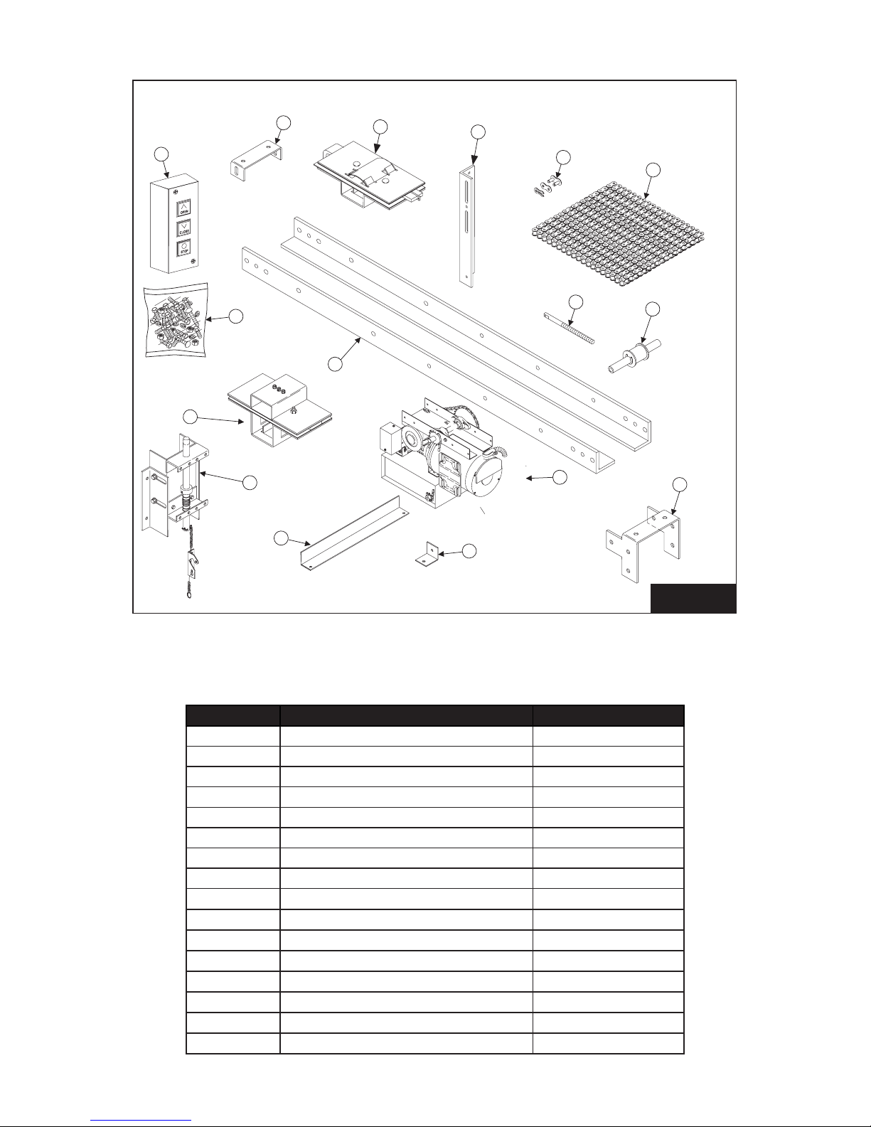
Item# Description Quantity
1 Track Rails 2
2 Spreader Bracket(s) As reqd.
3 Idler Roller Assembly (2 for Bi-part) 1
4 Drive/disc. Assembly (2 for Bi-part) 1
5Trolley Assembly (standard) 1
6Hanger Bracket Angle As reqd.
7Chain Take-Up Bolt 1
8 Operator Power Head 1
9 Drive Chain 1
10 Chain Connecting Link 2
11 Sway Brace 1
12 Sway Brace Clip 1
13 Hardware Package 1
14 3 Button Station 1
15 Trolley Assembly (Bi-Part) 1
16 Bi-Part Front Idler Bracket 1
FIGURE 1
COMPONENT IDENTIFICATION
COMPONENT IDENTIFICATION LISTING
IDLER
ROLLER
ASSEMBLY
BI-PART FRONT
IDLER BRACKET
3
CHAIN
9
6
5
2
STANDARD TROLLEY
SLIDE ASSEMBLY
SPREADER
BRACKET
THREE
BUTTON
STATION
HARDWARE
PACKAGE
TRACK RAILS
DRIVE/DISCONNECT
ASSEMBLY
SWAY BRACE SWAYBRACE CLIP
OPERATOR
POWER HEAD
7
10
16
14
13
1
8
4
15
11
12
HANGER
BRACKET
ANGLE CHAIN
CONNECTING
LINK
CHAIN TAKE-UP
BOLT
BI-PART
TROLLEY SLIDE
ASSEMBLY

6
IMPORTANT INSTALLATION NOTES
TO REDUCE THE RISK OF SEVERE INJURY OR DEATH, READ
& FOLLOW ALL INSTALLATION INSTRUCTIONS!
WARNING
• Install only on a properly operating Slide Door. An improperly operating door could cause
severe injury. Have a qualied service person make repairs to cables, spring assemblies,
and other hardware before installing the opener.
• Remove all ropes, and remove or make inoperative all locks that are connected to
the garage door before installing the opener (unless mechanically and/or electrically
interlocked to the power unit).
• Lightweight doors (berglass, aluminum etc.) must be reinforced to avoid door damage.
Check the door manufacturer’s instruction manual for a bracing procedure or the
availability of a Reinforcement Kit.
• PowerMaster Model GSL Slide Door operators are for Commercial Vehicular Slide Doors,
and as such, are NOT recommended for pedestrian trac. In installations where it is
known that the pedestrians will be nearby, ensure a pedestrian door is available for
entrance and exit to the building. In addition, YOU MUST install an auxiliary entrapment
protection device that is UL recognized and has been tested for use with this unit
(such as a reversing door edge or photoelectric beam device) as part of the compete
operator system.
• Connect an auxiliary entrapment protection device (reversing edge or photoelectric
device across the door opening). A device of this type is STRONGLY ADVISED FOR ALL
commercial operator installations. An auxiliary entrapment protection device is REQUIRED
when the three button control station is out of sight of the door or any other automatic or
manual control is used.
• Install the opener at least 8 feet or more above the oor.
• Do not connect the opener to the source of power until instructed to do so.
• Locate the control station:
a. Within sight of the door;
b. At a minimum height of 5 feet above the oor so small children cannot reach it; and
c. Away from the door, so the user is prevented from coming in contact with the door
while operating the controls.
• Do not overtighten the clutch adjustment to compensate for a poorly working door.
• Securely attach any WARNING signs or placards to either the door or above the control
station as directed.
• After installing the opener, all safety features must be tested for proper operation.
7
INSTALLATION INSTRUCTIONS
WARNING
SPRINGS, PULLEYS, CABLES AND MOUNTING HARDWARE
USED TO BALANCE YOUR GARAGE DOOR ARE UNDER EXTREME
TENSION AT ALL TIMES AND CAN CAUSE SEVERE INJURY OR
DEATH IF DISTURBED. DO NOT ATTEMPT ADJUSTMENT.
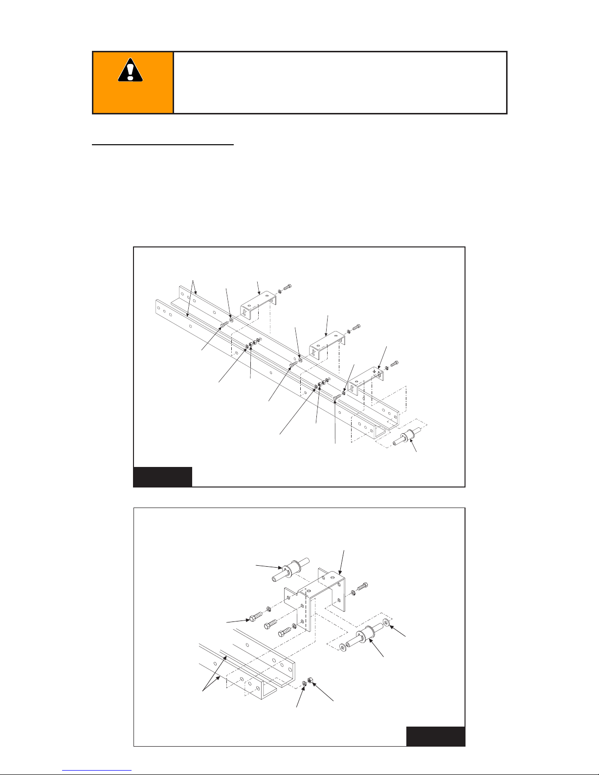
RAIL/CHAIN ASSEMBLY
TRACK ASSEMBLY
1. Lay Track Angles [#1] on work surface as shown in Figure 2.
2. Install Track Spreader Brackets [#2] and Front Idler Roller Assembly [#3] to one end of track
using 3/8 x 3/4 long hex head bolts and 3/8 lock washers, as shown in Figure 2.
FIGURE 2
FIGURE 2A
TRACK
ANGLE
[#1]
SPREADER
BRACKET
[#2]
SPREADER
BRACKET
[#2]
SPREADER
BRACKET
[#2]
3/8”
WASHERS
3/8” X 3/4”
LG. HEX HEAD
BOLTS
3/8” X 3/4”
LG. HEX HEAD
BOLTS
IDLER ROLLER
ASSEMBLY
[#3]
3/8” X 3/4”
LG. HEX HEAD
BOLTS
3/8”
WASHERS
3/8” LOCK
WASHERS
3/8” LOCK
WASHERS
3/8”
LOCK WASHERS
3/8”
HEX NUTS
3/8”
HEX NUTS
(6) 3/8” X 3/4”
LG. HEX HEAD
BOLTS
IDLER ROLLER
ASSEMBLY
[#3]
BI-PART FRONT
IDLER BRACKET
[#16]
IDLER ROLLER
ASSEMBLY
[#3]
(6) 3/8”
LOCK WASHERS
(2) 3/8”
WASHERS
(2) 3/8”
HEX NUTS
TRACK
ANGLE
[#1]

8
SLIDE ASSEMBLY
1. Assemble Top Plate, Lower Drive Plate, Center Drive Bar and two Nylon Inserts using two
5/16 x 1-1/4 carriage bolts, two 5/16 Lock Washers and two 5/16 Hex Nuts as shown in
Figure 3.
2. Install 3/8 Chain Take-up Bolt into Slide Assembly using one 3/8 Lock Washer and two 3/8
Hex Nuts as shown in Figure 3A. DO NOT TIGHTEN NUTS!
3. For Bi-Part Slide Assembly, see Figure 3B.
5/16 X 1-1/4”
CARRIAGE BOLTS
NYLON CHAIN
DEFLECTOR
CENTER
DRIVE BAR
LOWER
DRIVE PLATE
NYLON INSERTS
TOP PLATE
3/8” HEX NUT
3/8” HEX NUT
5/16” HEX NUTS
CENTER BAR
3/8” LOCK WASHER
5/15” LOCK WASHER
5/15” LOCK WASHER
TAKE UP
BOLT
#10 SOCKET HEAD
CAP SCREWS (3)
TROLLEY
CENTER GUIDE
DEEP ENGAGEMENT
LOWER DRIVE PLATE
5/16 X 1-1/4”
LG. CARRIAGE BOLTS
BI-PART TROLLEY
UPPER DRIVE PLATE
3/8” HEX NUT
3/8” HEX NUT
3/8” LOCK WASHER
3/8” LOCK WASHER
NYLON
INSERT
FIGURE 3A
FIGURE 3B

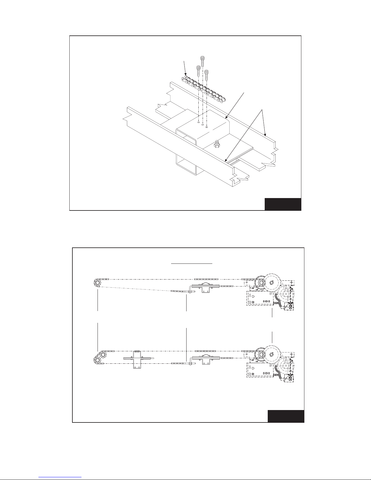
9
OPERATOR ASSEMBLY
1. Install Trolley Slide Assembly on Track Assembly with Chain Take-up Bolt [#7] pointing away
from end of track where Power Head [#8] will be mounted as shown in Figure 4.
NOTE: If Bi-Part installation, slide Bi-Part trolley slide on rst.
2. Mount Power Head to Track Assembly using four 3/8 x 3/4 Long Hex Head Bolts, four 3/8 Lock
Washers and four 3/8 Hex Nuts, as shown in Figure 4.
3. Turn operator assembly over and back o Chain Adjustment Nut to the end of the threads
on Chain Take-up Bolt [#7]. See Figure 5.
4. Lay out Drive Chain [#9] next to operator assembly work surface.
5. Thread one end of the Operator Drive Chain around Operator Drive Sprocket and connect to
the Drive Tab on the Trolley Slide Assembly with a Chain Connecting Link. See Figure 5A and
Figure 6.
6. Thread the other end of the Drive Chain [#9] around the Idler Roller Assembly [#3]. See
Figure 6.
7. Pull Drive Chain [#9] tight up to Trolley Traveler Assembly. Mark the link that lines up with
the hole on the chain take up bolt on Slide Assembly on Traveler Assembly and cut Drive
Chain to length.
NOTE: If installing a bi-part operator, Drive Chain [#9] must pass through Bi-Part Slide
Assembly [#15] before being connected to Chain Take Up Bolt [#7] on Standard Slide
Assembly [#5]. See Figure 5B and Figure 6.
8. Attach cut end of Drive Chain [#9] to Drive Tab on Trolley Traveler Assembly with a Chain
Connecting Link. See Figure 5A.
9. Adjust chain tension using Chain Adjusting Nut to remove excess slack. See Figure 5A.
Track
Assembly
Power Head
[#8] (4) 3/8”
Hex Head Bolts
(4) 3/8”
Hex Bolts
(4) 3/8”
Lock Washers
Standard Trolley
Slide Assembly
[#5] Bi-Part Trolley
Slide Assembly
(When Required)
[#15]
FIGURE 4

10
10. Lock in adjustment using Lock Washer and Lock Nut on Chain Take-up Bolt. See
Figure 5A.
NOTE: Leave Bi-part slider carriage free at this time.
11. Bolt the hanger bracket angles together as shown in Figure 7 to form mounting brackets.
Attach the mounting brackets to the track spreader brackets using the 3/8”bolts, lock
washers and nuts (See Figure 7A). Do not tighten as the distance from the wall to the
track will have to be adjusted later.
DRIVE CHAIN
[#9]
TRACK
ASSEMBLY
ASSEMBLY SHOWN IN THE
INVERTED POSITION
BI-PART
TROLLEY ASSEMBLY
[#15]
FIGURE 5A
FIGURE 5B
DRIVE
CHAIN
[#9]
LOCK
NUT
DRIVE TAB
[#9]
LOCK
WASHER
CHAIN
CONNECTING
LINK
[#10]
CHAIN
CONNECTING LINK
[#10]
CHAIN
ADJUSTING
NUT
CHAIN
TAKE-UP BOLT
[#7]
TROLLEY
ASSEMBLY
[#5]
11
ASSEMBLY SHOWN IN THE
NORMAL POSITION
DRIVE CHAIN
[#9]
TRACK
ASSEMBLY
BI-PART
TROLLEY ASSEMBLY
[#15]
FRONT IDLER
BI-PARTING SLIDE
SINGLE SLIDE
CHAIN ROUTING LAYOUT FOR SLIDE DOOR
OPERATORS WITH IDLER SPROCKETS
CHAIN TAKE UP
BOLT POWER HEAD
FIGURE 5C
FIGURE 6

(3) 3/8” HEX
HEAD BOLTS
HANGER
BRACKET ANGLE
[#6]
HANGER
BRACKET ANGLE
[#6]
HANGER
BRACKET ANGLE
[#6]
(3) 3/8” HEX NUTS
(3) 3/8” LOCK
WASHERS
56-1/2” FOR 8’, 12’, & 16’TRACK
32-1/2” FOR 10’ & 14’ TRACK
MOUNTING
BRACKET ANGLE
ASSEMBLY
LEFT TRACK ANGLE
RIGHT TRACK ANGLE
POWER HEAD
STANDARD
TROLLEY TRAVELER
BI-PART
TROLLEY TRAVELER
FRONT IDLER
SHAFT
SPREADER
BRACKET
SWAY BRACE
ANGLE CLIP
48”
(ALL CENTER SPACERS)
46”
FIGURE 7
FIGURE 7A
HANGER INSTALLATION

13
WARNING
TO AVOID DAMAGE TO DOOR AND OPERATOR, ENSURE ALL DOOR
LOCKS ARE DISABLED. USE AN INTERLOCK SWITCH IF A LOCK IS
REQUIRED TO RETAIN FUNCTIONALITY.
1. For single slide doors sliding right to open, locate rst angle mounting bracket 9” to the
left of the opening. For doors sliding left to open, locate rst angle mounting bracket 9”to
the right of the opening (See Figure 8).
NOTE: For bi-parting doors, this measurement is 15”. See Figure 9.
2. Set the assembled operator into position and mark the holes for the angle mounting
brackets on the wall, as low as possible without interfering with door travel (See
Figure 10). Drill holes in the wall for mounting. Through bolts are recommended for
this purpose. If wall construction does not permit the use of through bolts, lag bolts and
shields may be used.
3. Secure the assembled operator to the wall. IMPORTANT: BE SURE THE OPERATOR TRACK
AND DOOR TRACK ARE PARALLEL. Check that the door clears the power head when
moving. Adjust the track location on the mounting brackets to the desired position and
tighten all the bolts. It is recommended that at least one sway brace be used between
the wall and one of the track hangers for increased rigidity - especially on large or heavy
doors. See Figure 7A.
4. Mount the disconnect mechanism so that the top of the bracket is no more than 2”
below the slider carriage (See Figures 8, 10, 11). This mechanism may be adjusted
both front and back and up and down to align the disconnect pin. It may be necessary
to shim between the mechanism and the door to bring the pin out into the center line
of the track.
NOTE: For Bi-parting doors, mount both door disconnect mechanisms (See Figures 9,
10, 11)
5. It is necessary on a bi-part installation to bring the doors to a fully closed position for
proper synchronization. WIth both disconnect pins engaged in their respective carriages,
connect the drive chain to the bi-part slide assembly with the hardware provided (See
Figures 5C and 7).
6. Install disconnect chain lock as shown in Figure 11 so it will function as described in
Figure 12.

14
FIGURE 9
FIGURE 8
HANGER LAYOUT RIGHT HAND OPERATOR
BI-PART INSTALLATION
DISCONNECT CHAIN LOCK
9” DOOR OPENING
46”
1-1/4”
46”
1-1/4”
DISCONNECT CHAIN LOCK
DOOR OPENING
15”

15
SUITABLE FASTENERS BY
INSTALLER
POSITION 1
DOOR ENGAGED
DISCONNECT CHAIN LOCK
FOR MANUAL OPERATION,
PULL CHAIN AND LATCH
POSITION 2
DOOR
DISENGAGED
KEEP AS NARROW
AS POSSIBLE TO
REDUCE SWAY
TROLLEY SLIDE
ASSEMBLY
2” MAX.
4-1/4” MIN.
6-1/4” MAX.
(AVAILABLE ADJUSTMENT)
NOTE:
DISCONNECT SHAFT MUST
CLEAR TROLLEY TRAVELER
WHEN FULLY RETRACTED
DISCONNECT
DRIVE PLUNGER
AS REQUIRED
DISCONNECT
CHAIN LOCK
DISCONNECT
ASSEMBLY
6-3/4”
5-1/2”
2-1/2”
2” MIN.
4” MAX.
ADJUST HEIGHT OF
DISCONNECT ASSEMBLY
TO CENTER DRIVE
PLUNGER IN TROLLEY
SLIDE ASSEMBLY
THIS DIMENSION IS
DETERMINED BY ENGAGING
DRIVE PLUNGER ON
DISCONNECT ASSEMBLY WITH
TROLLEY SLIDE ASSEMBLY.
FIGURE 10
FIGURE 11
FIGURE 12

16
TO AVOID RISK OF ENTRAPMENT AND POSSIBLE DAMAGE
TO THE DOOR AND OPERATOR, THE LIMITS MUST BE
ADJUSTED BEFORE APPLYING POWER TO THE OPERATOR.
WARNING
SETTING THE LIMIT SWITCHES
1. Remove the cover on the electrical enclosure. There are two limit nuts on the threaded
limit shaft that move laterally along the shaft as the operator opens and closes the door.
When a limit nut nears the end of the shaft, it activates a (set of) switch(es). The Open Limit
Switch is on the LEFT, and the Close Limit Switch is on the RIGHT. Auxiliary switches may
also be present to control other function (They are mounted to a separate bracket and
should not be confused with the Open and Close limit switches, which are mounted on the
back of the electrical enclosure box and are somewhat hidden from view).
2. Manually set the door to a nearly closed position.
3. Refer to Figure 8. Depress the Limit Nut Retaining Bracket away from the slots in the limit
nuts. Turn the Close Limit Nut on the shaft until it engages the Close Limit Switch. The
switch will sound an audible “click” when engaged. If there are auxiliary switches present,
the limit switch will be the second“click.” Release the Retaining Bracket and be sure that it
engages in slots of both limit nuts.
4. Manually raise the door to a Nearly Open position, and repeat Step #3 with the Open Limit
Nut and Switch.
5. If auxiliary switches are present, the limit nut will actuate them just prior to activating the
Open or Close Limit Switch (This is pre-set at the factory).
6. Manually move the door
to a half-open position
to avoid door damage
due to incorrect power
supply phasing. On three-
phase units, the door may
initially run in the wrong
direction when power
is rst applied. With the
door in mid-position,
there will be time to stop
the door before damage
can happen if incorrect
phasing occurs.
7. A nal limit adjustment
will be necessary after
the connection of the
power supply in order to
ensure the door stops in
the proper Open and Close
positions. FIGURE 13
OPEN
LIMIT NUT
CLOSE
LIMIT NUT
LIMIT
SHAFT
LIMIT NUT
RETAINER PLATE
OPEN
LIMIT SWITCH
CLOSE
LIMIT SWITCH

17
NOTE: PowerMaster GSL operators have been
designed and constructed for use with voltages
from 115 Volts AC to 575 Volts AC, in single or
three phase. Check the operator nameplate
label on the control box cover for the proper
voltage and phase. The application of an
improper input voltage or phase will result in
catastrophic failure to the internal electrical
components. Observe local electrical codes
when wiring the operator.
When hard wiring, observe state and local
electrical codes. A wiring diagram is attached
to the inside of the control box cover. Connect
the appropriate voltage and phase power
leads to the appropriate terminals as per the
wiring diagram and connect a ground wire to
the grounding screw. On three phase units,
incorrect phasing of the power supply will cause
the motor to rotate in the wrong direction (It
will open when Close button is pushed and vice
versa). To correct this, interchange any two of the
incoming three phase conductors.
The wiring diagram attached inside the cover
of the control box details all of the eld wiring
terminal connections for the operator. Always
connect the wires to the push button controls
and auxiliary devices exactly as shown.
Warning: Control voltage of the operator is 24 Volts AC, Class 2. Do not run the power
leads and control circuit wiring in the same electrical conduit.
NOTE: All GSL operators are pre-wired to accept reversing edge components. To comply with
UL requirements, one of these systems must be installed and wired to the operator.
For operator models not installed with
reversing edge components or photoelectric
device, ONLY ONE THREE BUTTON STATION OR
A CONTROL WIRED FOR CONSTANT PRESSURE
TO CLOSE MAY BE USED TO CONTROL THE
OPERATOR. THIS IS TO COMPLY WITH UL
SAFETY REQUIREMENTS. IN THIS CASE, THE
CONTROL STATION MUST BE LOCATED WITHIN
CLEAR SIGHT OF THE DOOR ADJACENT TO THE
CONTROL STATION, THE WARNING PLACARD
INCLUDED WITH THE OPERATOR MUST BE
INSTALLED (Figure 14)
TO PREVENT THE RISK OF PERSONAL
INJURY AND/OR DAMAGE TO DOOR
OR PROPERTY, ONLY OPERATE DOOR
CONTROL WHEN DOOR IS IN CLEAR
VIEW. IF CONTROL STATION CANNOT BE
LOCATED WHERE THE DOOR IS VISIBLE,
OR IF ANY OTHER DEVICE IS USED TO
CONTROL THE DOOR, AN AUXILIARY
ENTRAPMENT DEVICE MUST BE
CONNECTED TO THE UNIT.
WARNING
ELECTRICAL WIRING INSTRUCTIONS
TO PREVENT THE RISK OF PERSONAL
INJURY OR DEATH:
• DISCONNECT POWER AT THE FUSE
BOX BEFORE PROCEEDING
• ELECTRICAL CONNECTIONS
MUST BE MADE BY A QUALIFIED
INDIVIDUAL
• OBSERVE LOCAL ELECTRICAL CODES
WHEN WIRING THE OPERATOR
WARNING
WARNING: TO PREVENT
ENTRAPMENT, DO
NOT START DOOR
DOWNWARD TRAVEL
UNLESS DOORWAY IS
CLEAR
FIGURE 14

18
TO AVOID DAMAGE TO DOOR AND
OPERATOR, ENSURE ALL DOOR LOCKS
ARE DISABLED. USE AN INTERLOCK
SWITCH IF A LOCK IS REQUIRED TO
RETAIN FUNCTIONALITY.
CAUTION
ACCEPTED SAFETY EQUIPMENT
• Photoelectric safety sensors manufactured
by Linear Corp.
• Door Edge Sensor and Interface Module
manufactured by Miller Edge model series
designated ME, MT, MU and CPT223 with
sux T2 provided with interface module
model Signature Module model SM-102.
• Optical Door Edge Sensor and Photo Eye manufactured by Fraba Inc. models
OPTOEDGE, OPTOEYE; Part Nos. OSE-T, OSE-R, OSE-P, OPE.
SEE MANUFACTURER’S INSTRUCTIONS FOR INSTALLATION OF THIS SAFETY EQUIPMENT.
RISK OF ENTRAPMENT THAT MAY RESULT IN SERIOUS PERSONAL INJURY
OR DEATH. DISCONNECT POWER TO THE OPENER BEFORE AND DURING
INSTALLATION OF AN ACCESSORY, REVERSING DOOR EDGE OR PHOTOELECTRIC
DEVICE. DO NOT RECONNECT POWER TO OPENER UNTIL INSTRUCTED TO DO SO.
ENSURE DOORWAY IS CLEAR BEFORE STARTING TESTING OF UNIT.
WARNING

19
• NEVER let children operate or play with door controls. Keep remote control away from
children.
• ALWAYS keep a moving door in sight and keep people and objects away from the door
area until the door is completely closed. NO ONE SHOULD CROSS THE PATH OF A
MOVING DOOR.
• TEST THE DOOR OPENER’S REVERSING FEATURE MONTHLY (where applicable).
• After adjusting the force setting, if equipped with a clutch or the limit of travel, ALWAYS
RETEST THE OPENER. Failure to adjust the opener properly may result in damage to the
door or operator.
• DO NOT over adjust the force setting (clutch) to compensate for a poorly
working door.
• KEEP THE GARAGE DOOR PROPERLY BALANCED (See the door owner’s manual).
• AN IMPROPERLY BALANCED DOOR MAY CAUSE SEVERE INJURY OR DEATH.
• Have a QUALIFIED SERVICE PERSON make repairs to cables, spring assemblies and
other hardware.
• SAVE THIS INSTRUCTION MANUAL AND GIVE IT TO THE END USER.
NOTE: It is now necessary to turn on the power in order to run the Opener to check for
proper operation and limit settings. Before doing so, ensure that all mounting hardware
are installed and properly tightened, that all electrical connections are per local code
requirements, and that proper wiring practices have been followed. Also, double-check
that all ropes and installation support hardware have been removed from the door and
that the doorway is clear.
WIRING TERMS
MOMENTARY CONTACT: Button can be
pushed and then released and door will keep
moving or stop without maintaining pressure
on the button.
CONSTANT PRESSURE: Constant pressure is
required on the button in order for continued
door movement. When the button is released,
the door will stop and possibly reverse to full
open depending on wiring type.
DOOR EDGE/ PHOTOELECTRIC INPUT: The
operator wiring provides for input from an
electric door safety edge or photoelectric
device that will cause a closing door to stop
and reverse it to open.
IMPORTANT SAFETY INSTRUCTIONS FOR OWNER
TO REDUCE THE RISK OF SEVERE INJURY OR DEATH:
READ AND FOLLOW ALL INSTRUCTIONS!
WARNING
FAILURE TO TEST REVERSING SYSTEM
COULD RESULT IN DEATH OR SERIOUS
INJURY. TEST THIS SYSTEM ONCE A
MONTH.
WARNING
AVOID ELECTROCUTION: DO NOT
ROUTE LOW VOLTAGE WIRES IN SAME
CONDUIT AS HIGH VOLTAGE WIRES.
FOLLOW ALL LOCAL ELECTRICAL
CODES OR THE NATIONAL
ELECTRICAL CODE (NEC).
WARNING

20
RISK OF ENTRAPMENT THAT MAY
RESULT IN SEVERE INJURY OR DEATH!
DISCONNECT POWER TO THE OPERATOR
BEFORE SERVICING OR MAKING
ADJUSTMENTS. ENSURE DOORWAY
IS CLEAR BEFORE STARTING TESTING
OF UNIT.
WARNING
ALWAYS DISCONNECT POWER TO
THE OPERATOR BEFORE SERVICING,
CONNECTING ACCESSORY DEVICES
OR MAKING ADJUSTMENTS.
CAUTION
The clutch serves to protect the door, the
electric operator and other equipment from
undue stress or damage caused by starting
forces and/or an obstruction to the door. It
should be set NO TIGHTER than is necessary
to smoothly and consistently move the door
throughout its full range of travel. When
properly set, it will slip freely if the door should
encounter an obstruction, and it should be
possible to stop the travel of the door by hand.
WARNING: BEFORE ADJUSTMENT, REMOVE
POWER TO THE OPERATOR!
CAUTION: NEVER COMPRESS CLUTCH SPRING
BEYOND POINT LIMITED BY THE DESIGN
OF THE OPERATOR OR REPLACE IT WITH A
HEAVIER SPRING.
Due to changing conditions of the door
and normal wear, it may be necessary to
occasionally re-adjust the clutch to obtain
dependable operation.
WARNING: BEFORE DOING SO, BE
CERTAIN THAT THE DOOR IS IN GOOD
WORKING CONDITION, IS PROPERLY
COUNTERBALANCED, AND THAT THE CLUTCH IS NOT SLIPPING BECAUSE OF LOOSE OR
MISSING HARDWARE, BINDING IN THE TRACK, RUBBING AGAINST THE DOOR STOPS, OR
DEFECTIVE OR MISADJUSTED SPRINGS. ANY SERVICE REQUIRED TO THE DOOR, DOOR SPRINGS
OR DOOR OPERATOR MUST BE PERFORMED BY A QUALIFIED PROFESSIONAL DOOR INSTALLER.
The clutch pads will wear during normal operation and should be replaced when it becomes
dicult or impossible to suciently tighten the clutch to obtain smooth operation of the
door when it is in good working condition. To
replace the clutch pad, rst move the door to
the closed position. Loosen and remove the
clutch nuts and spring. Remove the pressure
plate and other clutch pad.
To replace the inside clutch pad, loosen the
set screws on the drive hub and remove it.
When reassembling the clutch, tighten the
drive hub set screws after the adjustment
nuts are tightened enough to compress the
clutch springs.
IMPROPER ADJUSTMENT OF CLUTCH
SETTING COULD CAUSE ENTRAPMENT,
INJURY OR DEATH. SET CLUTCH
ADJUSTMENT FOR JUST ENOUGH FORCE
TO OPERATE THE DOOR RELIABLY, BUT
NO STRONGER. CONTACT A SERVICE
PROFESSIONAL TO CORRECT ANY
BINDING, STICKING OR OTHER DOOR
PROBLEMS. DO NOT OVERADJUST
CLUTCH SETTING TO COMPENSATE FOR
A POORLY WORKING DOOR.
WARNING
CLUTCH ADJUSTMENT
FIGURE 15
ADJUSTING
NUTS (4)
CLUTCH
ASSEMBLY
Clutch Adjustment: The clutch is set to its lightest
adjustment by the manufacturer. To tighten the
clutch, turn all four of the clutch adjustment nuts
clockwise in 1/4 turn increments.
OPERATION AND ADJUSTMENT INSTRUCTIONS
Table of contents
Other Power Master Garage Door Opener manuals


Popular Garage Door Opener manuals by other brands


Serai
Serai KIT/18F installation manual

quiko
quiko SCARABEO QK-SCA24 manual

Overhead door
Overhead door RapidSlat 611 Operational & maintenance manual

Craftsman
Craftsman 139.53902D owner's manual

Chamberlain
Chamberlain 182649 owner's manual

Wayne-Dalton
Wayne-Dalton 7100 Series Installation instructions and owner's manual