Power Master GT Installation instructions


READ THESE STATEMENTS CAREFULLY AND FOLLOW THE
INSTRUCTIONS CLOSELY!
The Warning and Caution boxes throughout this manual are there to protect
you and your equipment. Pay close attention to these boxes as you follow the
manual.
WARNING
Indicates a MECHANICAL hazard
of INJURY OR DEATH. Gives
instructions to avoid the hazard.
CAUTION
Indicates a MECHANICAL hazard
of DAMAGE to your operator or
equipment. Gives instructions to
avoid the hazard.
Indicates an ELECTRICAL
hazard of INJURY OR DEATH.
Gives instructions to avoid the
hazard.
WARNING CAUTION
Indicates an ELECTRICAL hazard
of DAMAGE to your operator or
equipment. Gives instructions to
avoid the hazard.
TABLE OF CONTENTS
2
Model GT Drawbar Operator Applications– Product Features .......................................................….3
Preparation ...........................................................................................................................................4-7
Component Identification Pictorial - Figure 1 ....................................................................... 4
Important Installation Notes (Things To Do Before/During Installation)............................. 5
Component Identification Listing - Table 1 ........................................................................... 5
Rail/Chain Assembly Instructions - Figure 2 …...………………………………………………..6
Trolley Assembly Instructions - Figure 3 ………………………………..…………………......6-7
Operator Assembly Instructions Figure 4,5, & 6 ................................................................ ..7
Operator Installation ..........................................................................................................................8-14
Operator Installation Figure 7 & 8........................................................................................... 8
Preparing Mounting Pad - Figure 9......................................................................................... 9
Hanging Power Head - Figure 10 .......................................................................................... 10
Assembling Door Arm - Figure 11 ........................................................................................ 11
Attaching Door Arm to Door - Figure 12............................................................................... 11
Setting The Limits - Figure 13............................................................................................... 12
Electrical Wiring Instructions................................................................................................ 13
Pneumatic Door Edge Installation - Figure 14..................................................................... 14
Field Wiring - Figure 15.......................................................................................................... 14
Operation and Adjustment Instructions......................................................................................... 15-17
Important Safety Instructions for Owner............................................................................... 15
Wiring Terms............................................................................................................................ 15
Clutch Adjustment - Figure 16 ............................................................................................... 16
Testing...................................................................................................................................... 17
Maintenance .......................................................................................................................................... 18
Trouble Shooting................................................................................................................................... 19
Wiring Diagram - Single Phase 331-3 ................................................................................................. 20
Wiring Diagram - Three Phase 333-3.................................................................................................. 21
Wiring Diagram - Single Phase 1331-3 ............................................................................................... 22
Wiring Diagram - Three Phase 1333-3................................................................................................ 23
Warranty................................................................................................................................................. 24

The purpose of this booklet is to provide
assembly, installation and operation information
concerning PowerMaster Model GT Drawbar
Commercial Vehicular Garage Door Operators
and related Accessory Products.
NOTE: IT IS IMPORTANT THAT THIS
INSTRUCTION MANUAL BE READ AND
UNDERSTOOD COMPLETELY BEFORE
INSTALLATION OR OPERATION IS
ATTEMPTED. IT IS INTENDED THAT THE
INSTALLATION OF THIS UNIT WILL BE DONE
ONLY BY PERSONS TRAINED AND
QUALIFIED IN THE INSTALLATION,
ADJUSTMENT AND SERVICE OF
COMMERCIAL OVERHEAD DOORS AND
DOOR OPERATORS AND BY QUALIFIED
ELECTRICIANS.
NOTE:THE IMPORTANT SAFEGUARDS AND
INSTRUCTIONS IN THIS MANUAL CANNOT
COVER ALL POSSIBLE CONDITIONS AND
SITUATIONS WHICH MAY OCCUR DURING
ITS USE. IT MUST BE UNDERSTOOD THAT
COMMON SENSE AND CAUTION MUST BE
EXERCISED BY THE PERSON(S) INSTAL-
LING, MAINTAINING AND OPERATING THE
EQUIPMENT DESCRIBED HEREIN. DO NOT
USE THIS EQUIPMENT FOR ANY OTHER
THAN ITS INTENDED
PURPOSE - OPERATING OVERHEAD
COMMERCIAL VEHICULAR GARAGE
DOORS.
STANDARD FEATURES:
Limit Switches: Rotary limit switches, easily
adjusted over a wide range. The motor may be
removed without affecting the limit switch
adjustments.
Manual Release: Permits manual operation
of the door in the event of a power failure.
The Model T is equipped with a door arm
disconnect to aid in manual operation. Use
of this feature will not affect the limit switch
adjustment.
Control Circuit: Standard three button open,
close and stop. 24 Volts AC.
Connections For Auxiliary Entrapment
Protection Devices: Use with pneumatic
reversing door edge components or a
photoelectric beam (across the opening) device.
Constant Contact To Close: Standard
operation.
Momentary Contact To Close: Feature can be
activated by simply moving a wire on the
terminal strip.
OPTIONAL FEATURES:
Digital Radio Controls: Open, Close and
Stop operation. Radio units are available to
control up to 27 doors from one transmitter
Digital Timer to Close: Adjustable from 0 to
17 minutes in one second intervals.
Keyless Entry System: Connection terminals
provided for hard wired or wireless keyless
entry systems.
PRODUCT FEATURES 3
Model GT Drawbar Operator Applications
Drawbar operators are intended for
commercial and industrial use on sectional
overhead doors which use horizontal track
with normal radius. A drawbar operator is not
suitable for doors with high lift or vertical lift
doors. The installation requires a minimum
clearance of 8 inches above the highest point
of the door at any point in its travel. Please
refer to Figure 10, on page 10 for back room
requirements.
A drawbar operator when properly installed
will effectively lock the door in the closed
position.
Model GT Drawbar operators are used in
the following applications:
- Heavy Duty, Indoor Commercial
installations only
- Up to 20 foot high doors with a maximum
area of 575 square feet maximum area -
slightly higher for lighter doors - consult
factory.
- Use with foam/pneumatic reversing door
edge or photoelectric device - REQUIRED
where the 3-button station is out of sight of
the door, or any other automatic, remote or
manual control is used to activate the door.

FIGURE 1 - COMPONENT IDENTIFICATION
PREPARATION
4
Before starting the installation of the operator, the door
must be in good working condition and properly
counterbalanced. Inspect the door and track for loose
or missing hardware. Test the door manually for
balance and ease of operation. Lubricate door hinges
and rollers. If necessary, employ a qualified technician
to adjust the springs for proper counterbalance of the
door.
Before removing the operator powerhead from the
shipping carton, inspect the nameplate on the cover of
the operator control box to verify that it is the correct
model for the intended application and that the voltage
and phase are in accordance with electrical
power provided at the job site. The rails are
shipped separately from the power head.
Warning: Rope off the area to keep
personnel and vehicles clear of the door
and floor space in the vicinity of the
operator during the installation.
ELECTRIC DOOR OPENERS ARE DESIGNED FOR
DOORS IN GOOD WORKING CONDITION,
PROPERLY COUNTERBALANCED AND PROPERLY
ADJUSTED IN ACCORDANCE WITH THE DOOR
MANUFACTURER'S INSTALLATION INSTRUCTIONS.
WARNING
REMOVE OR DISABLE ANY LOCKING
DEVICES FROM DOOR AND REMOVE ALL
ROPES.
WARNING
SPRINGS ARE SUBJECT TO VERY HIGH
FORCES AT ALL TIMES AND ADJUSTMENTS
MUST BE MADE ONLY BY A QUALIFIED
PROFESSIONAL DOOR INSTALLER.
WARNING
-13
DOORBRACKET
OPERATOR
POWER HEAD
8
-11 -12
HARDWARE
PACKAGE
-14
-1 TRACK RAILS
-4
SPREADER
BARS
IDLER ROLLER
ASSEMBLY
-3
-7
CHAIN TAKE-UP
BOLT
UPPER HALF
TROLLEY
ASSEMBLY
-5
-6
-2
FRONT TRACK
BRACKET
-15
THREE
BUTTON
STATION
-11 -9
CHAIN
CONNECTING
LINK
CHAIN
FIG. 1
DOOR
CONNECTING
ARMS
LOWER HALF
TROLLEY
ASSEMBLY

• Install only on a properly balanced garage
door. An improperly balanced door could cause
severe injury. Have a qualified service person
make repairs to cables, spring assemblies and
other hardware before installing the opener.
• Remove all ropes and remove or make
inoperative all locks (unless mechanically and/or
electrically interlocked to the power unit) that are
connected to the garage door before installing
the opener.
• Lightweight doors (fiberglass, aluminum etc.)
must be reinforced to avoid door damage.
Check the door manufacturer’s instruction
manual for a bracing procedure or the availability
or a Reinforcement Kit.
• PowerMaster Model T Drawbar operators are
Commercial Vehicular Door Operators and as
such are NOT recommended for pedestrian
traffic. In installations where it is known that
pedestrians will be nearby ensure a pedestrian
door is available for entrance and exit to the
building. In addition YOU MUST install an
auxiliary entrapment protection device (reversing
door edge or photoelectric beam device) as part
of the compete operator system.
• Connect an auxiliary entrapment protection
device (reversing edge or photoelectric device
across the door opening). A device of this type
is STRONGLY ADVISED FOR ALL commercial
operator installations. An auxiliary entrapment
protection device is REQUIRED when the
three button control station is out of sight of the
door or any other automatic or manual control
is used.
• Install the opener at least 8 feet or more
above the floor.
• Do not connect the opener to the source of
power until instructed to do so.
• Locate the control station:
a) within sight of the door and;
b) at a minimum height of five feet above
the floor and;
c) away from all moving parts of the
door.
• Do not overtighten the clutch adjustment to
compensate for a poorly working door.
• Securely attach any WARNING signs or
placards to either the door or above the control
station as directed (see page 11).
• After installing the opener, all safety features
must be tested for proper operation (see page
17).
TO REDUCE THE RISK OF SEVERE INJURY
OR DEATH: READ AND FOLLOW ALL
INSTALLATION INSTRUCTIONS!
WARNING
IMPORTANT INSTALLATION NOTES
Item # Description Qty. Item # Description Qty.
1 Track Rails 2 9 Drive Chain 1
2 Front Track Bracket 1 10 Chain Connecting Link 1
3 Idler roller assembly 1 11 Curved door Arm 1
4 Track spreader bars 2 12 Straight Arm w/Disconnect 1
5 Upper Half of Trolley Assembly 1 13 Door bracket 1
6 Lower Half of Trolley Assembly 1 14 Hardware package 1
7 Chain Take-Up Bolt 1 15 3 Button Station 1
8 Operator Power head 1
TABLE 1 - COMPONENT IDENTIFICATION LISTING
5

6
Track Assembly
1. Lay Track Angles (1) on work surface as shown in Figure #2.
2. Install front track Bracket (2) and Front Idler Roller Assembly (3) to one end of track using 3/8 x ¾
long hex head bolts and 3/8 lock washers, as shown in Figure #2.
3. Install two track spreader bars (4), evenly spaced over length of track using 3/8 x ¾ long hex
head bolts and 3/8 lock washers, as shown in Figure #2.
RAIL/CHAIN ASSEMBLY
3/8"
LOCK WASHER
3/8 X3/4"
LG. HEX
HEAD BOLT
3/8 X 3/4"
LG. HEX
HEAD BOLT
3/8"
LOCK WASHER
TRACK
ANGLE
-1
-1
TRACK
ANGLE
TRACK
SPREADER
BAR
-4
TRACK
SPREADER
BAR
-4 IDLER ROLLER
ASSEMBLY
-3
-2
FRONT TRACK
BRACKET FIG. 2
SPRINGS, PULLEYS, CABLES AND MOUNTING HARDWARE USED TO
BALANCE YOUR GARAGE DOOR ARE UNDER EXTREME TENSION AT ALL
TIMES AND CAN CAUSE SEVERE INJURY OR DEATH IF DISTURBED.
DO NOT ATTEMPT ADJUSTMENT.
WARNING
Trolley Assembly
1. Assemble upper half of trolley to lower half of trolley (6) using two 5/16 x 1 ¼ carriage bolts, two
5/16 lock washers and two 5/16 hex nuts as shown in Figure # 3.
2. Install 3/8 chain take-up bolt (7) into trolley assembly using one 3/8 lock washer and two 3/8 hex
nuts as shown in Figure # 3. (DO NOT TIGHTEN NUTS)
3. Install 3/8 x 2” long hex head bolt through ears on lower half of trolley (6) and secure in position
with 3/8 lock washer and 3/8 hex nut.
3/8"
LOCK WASHER
3/8 X 3/4"
LG. HEX
HEAD BOLT
3/8 X 3/4"
LG. HEX
HEAD BOLT
3/8"
LOCK WASHER
TRACK
ANGLE
-1
-1
TRACK
ANGLE
TRACK
SPREADER
BAR
-4
TRACK
SPREADER
BAR
-4 IDLER ROLLER
ASSEMBLY
-3
-2
FRONT TRACK
BRACKET
FIG. 2
3/8"
LOCK WASHER
3/8 X 3/4"
LG. HEX
HEAD BOLT
3/8 X 3/4"
LG. HEX
HEAD BOLT
3/8"
LOCK WASHER
TRACK
ANGLE
-1
-1
TRACK
ANGLE
TRACK
SPREADER
BAR
-4
TRACK
SPREADER
BAR
-4 IDLER ROLLER
ASSEMBLY
-3
-2
FRONT TRACK
BRACKET
FIG. 2

7
INSTALLATION INSTRUCTIONS
-7 5/16 X 1-1/4" LG.
CARRAGE BOLTS
3/8"
HEX NUT
3/8" LOCK
WASHER
-5
3/8"
HEX NUT
5/16"
HEXNUT
5/16" LOCK
WASHER
-6
LOWER HALF
OF TROLLEY
3/8"
HEX NUT
3/8" LOCK
WASHER
3/8 X 2" LG.
HEX HEAD
BOLT
UPPER HALF
OF TROLLEY
FIG. 3
Operator Assembly
1. Install trolley slide assembly on track
assembly with chain take-up bolt (7) pointing
towards end of track where power head (8)
will be mounted as shown in Figure # 4.
2. Mount power head to track assembly using
four 3/8 x ¾ long hex head bolts, four 3/8 lock
washers and four 3/8 hex nuts, as shown in
Figure # 4.
3. Turn operator assembly over and back off
chain adjustment nut to the end of the threads
on chain take-up bolt (7). See Figure # 5.
4. Layout drive chain (9) next to operator
assembly work surface.
5. Thread one end of the operator drive chain
around operator drive sprocket and connect to
the chain take-up bolt (7) on trolley assembly
with a chain connecting link. See Figure # 5
and Figure # 6.
6. Thread the other end of the drive chain (9)
around the idler roller assembly (3).See
Figure #6.
7. Pull drive chain (9) tight up to trolley traveler
assembly; mark link that lines with drive tab
on traveler assembly and cut drive chain to
length.
8. Attach cut end of drive chain (9) to drive tab
on trolley traveler assembly with a chain
connecting link. See Figure # 5.
9. Adjust chain tension using chain adjusting nut,
to remove excess slack. See Figure # 5
10.Lock in adjustment using lock washer and
lock nut on chain take up bolt (7). See Figure
# 5.
-7
TROLLEY
SLIDE
ASSEMBLY
(4) 3/8"
HEXNUTS -8
POWER HEAD
TRACK
ASSEMBLY
(4) 3/8" LOCK
WASHERS
(4) 3/8 X 3/4" LG.
HEXHEAD
BOLTS
FIG. 4
(9) CHAIN CONNECTING
LINK LOCK NUT
-7
CHAIN
ADJUSTING
NUT TROLLEY
ASSEMBLY
LOCK
WASHER
DRIVE TAB
(9)
CHAIN
CONNECTING
LINK
FIG. 5
Unit is shown in the inverted position to facilitate
assembly of trolley track and traveler. When
properly installed the power head and trolley
assembly should face the floor. Note: Install drive
chain so Trolley Assembly is located near front idler
as shown.
DRIVE
SPROCKET
DRIVECHAIN TROLLEY
ASSEMBLY
(3)
IDLER
ROLLER
ASSEMBLY
(9)
FIG. 6

INSTALLATION INSTRUCTIONS 8
TO AVOID DAMAGE TO DOOR AND OPERATOR
ENSURE ALL DOOR LOCKS ARE DISABLED.
USE AN INTERLOCK SWITCH IF A LOCK IS
REQUIRED TO RETAIN FUNCTIONALITY.
WARNING
1. Locate the center of the door and mark a line
on the wall directly above the door. Extend this
line approximately 20” up the wall. See Figure 7.
CENTER OF DOOR OPENING
2. Slowly raise the garage door and observe the
action of the top section. When the top section
reaches the highest point (high arc), use a level
and project a line from this point to the center of
the door. See Figure 8.
P
ROJECTED LINE
CENTER OF DOOR
DOOR
RAISED TO
HIGH ARC
LEVEL
3. Using the projected lines for location, mount a
suitable wood block or angle iron, depending on
the structure of the building, to the wall above
the door opening as shown in Figure 7. Ensure
the block or angle iron used will provide a sound
and secure mounting pad for the operator track
front mounting bracket, see warning below. Drill
the required holes for mounting the operator
track front mounting bracket as shown in
Figure 9 on following page.
Figure 8
Figure 7

1-3/4" 1-3/4"
PROJECTED
LINE
4-1/2" MIN.
1/4" DIA. PILOT
HOLES FOR
3/8" DIA. LAG BOLTS
WOOD BLOCK MOUNTING PAD
C
L
1-3/4" 1-3/4"
PROJECTED
LINE
4-1/2" MIN.
13/32" DIA.HOLES
FOR 3/8" DIA. HEX
HEAD BOLTS
ANGLE IRON MOUNTING PAD
C
L
INSTALLATION INSTRUCTIONS
9
4. Raise operator and track assembly into
mounting position, as shown in Figure #10.
Temporarily support by suspending from
ceiling with suitable ropes or chains or
supporting from floor to operator.
5. Secure track front bracket to predrilled wood
or angle iron mounting pad as shown in Figure
# 10 . Insure that operator track assembly is
level, and secure power head to ceiling
structure as shown.
Note. Figure #10 on page 10, depicts a typical
method of hanging the power head of the
operator from the ceiling. Each installation will
vary due to the difference in building structures.
Side braces should always be used to further
support the power head.
6. Fully close the door and move the trolley to
within 2 inches of the front idler roller. Using
Figure #11 on page 11, as a guide, connect
the release arm (Item #12) to the trolley .
Connect the door curved arm (Item 11) to
the door release arm with (2) 3/8 x 1-1/4
“ bolts , lock washers, and nuts.
7. Refer to Figure #12, page 11. Attach the
door bracket (Item #13) to the curved arm
using a 3/8 x 1-1/4 “ bolt (2) 3/8 hex nuts.
Install the nuts until snug and then back off
leaving 1/16” clearance to allow the arm to
pivot on the bolt freely. Secure adjustment by
locking nuts against each other.
Position the door bracket to the scribed center
line on the door. Attach to door with (2) 5/16 x
2-1/2 long carriage bolts, lock washers and
nuts.
TO AVOID DAMAGE TO THE DOOR TOP SECTION
REINFORCE THE CENTER STILE WITH A VERTICAL
BRACE. ADDITIONAL/BRACING REINFORCEMENT
MAY BE REQUIRED WHEN THE DOOR IS
CONTROLLED BY AN AUTOMATIC DOOR OPERATOR:
CONSULT THE DOOR MANUFACTURER FOR
INSTRUCTIONS.
CAUTION
BEFORE PROCEEDING: RE-CHECK
ALL BOLTS, NUTS AND LAG SCREWS
AND ENSURE THEY ARE TIGHT!
NOTE
THE FRONT MOUNTING SURFACE MUST BE SOUND
AND SECURE. IF NECESSARY PROVIDE
REINFORCEMENT IN THIS AREA BEFORE MOUNTING
THE OPERATOR RAIL FRONT MOUNTING BRACKET.
WARNING
Figure 9
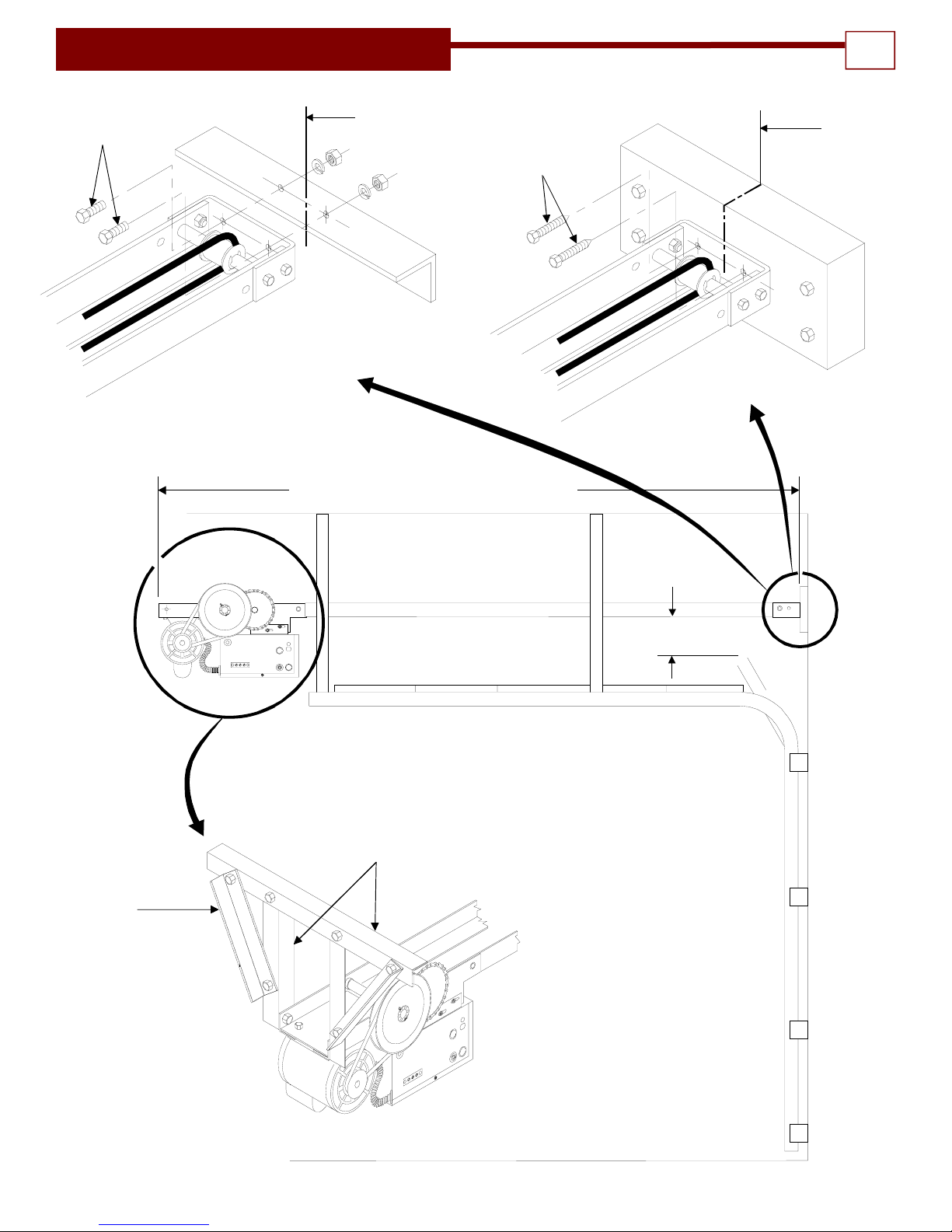
INSTALLATION INSTRUCTIONS 10
LEVEL
3-1/2" MIN.
CENTER LINE
OF DOOR
ANGLE IRON
MOUNTING PAD
3/8" HEX HEAD BOLTS
(BY OTHERS)
WOOD BLOCK
MOUNTING PAD
CENTER LINE
OFDOOR
3/8" LAGBOLTS
(BY OTHERS)
SIDE BRACE
(2) PLCS.
(BY OTHERS)
ANGLE IRON SUPPORTS
(BY OTHERS)
OVERALL LENGTH = DOOR HEIGHT PLUS 4'-9"

INSTALLATION INSTRUCTIONS
11
DOOR ARM
ASSY.
DOOR
CENTER LINE
(BY OTHERS)
3/8" NUTS
3/8 X 1-1/4" LG.
HEXHEAD BOLT
3/8 X 1-1/4" LG.
HEX HEAD BOLTS
3/8" LOCKWASHERS
AND NUTS
Figure 11
Figure 12
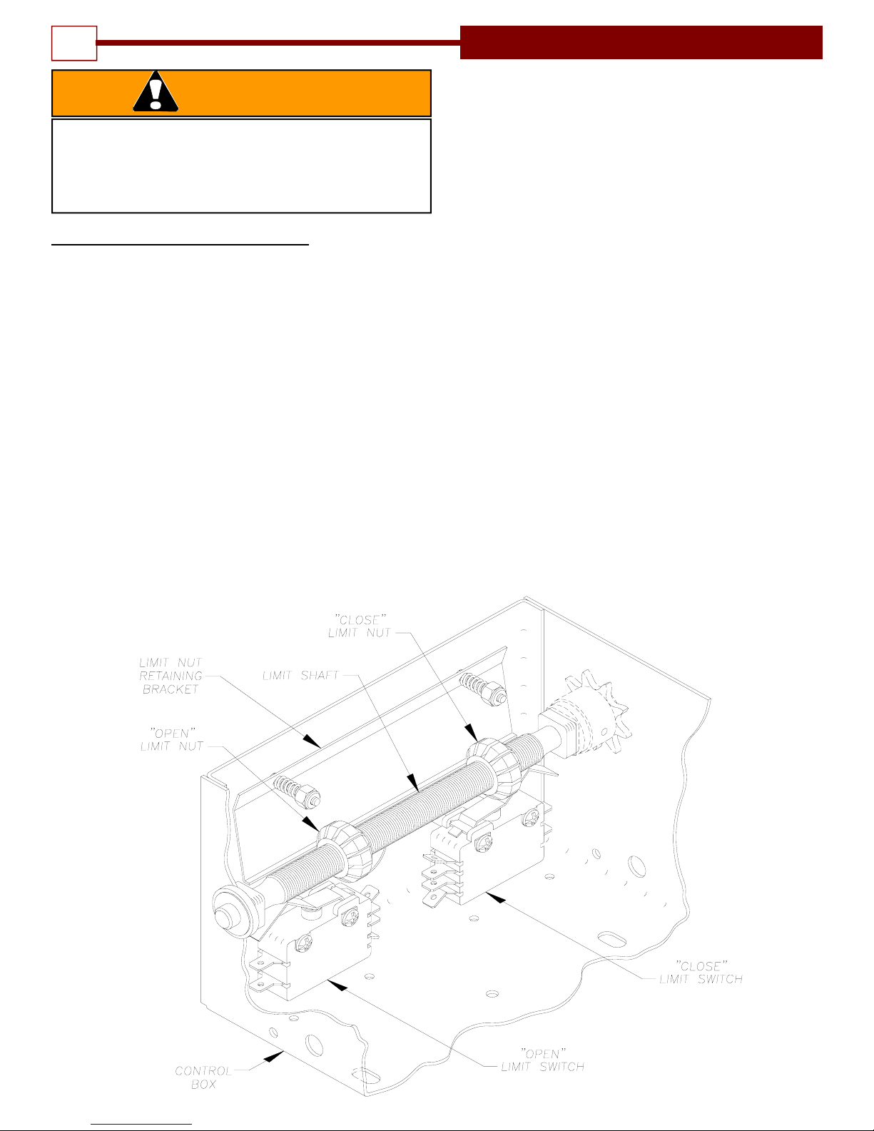
SETTING THE LIMIT SWITCHES
1. Remove the cover on the electrical enclosure. There are
two limit nuts on the threaded limit shaft that move
laterally along the shaft as the operator opens and
closes the door. When a limit nut nears the end of the
shaft it activates a (set of) switch(es). The OPEN limit
switch is on the LEFT and the CLOSE limit switch is on
the RIGHT. Auxiliary switches may also be present, they
are used to control other functions. These are mounted
on a separate bracket and should not be confused with
the the OPEN and CLOSE Limit Switches which are
mounted on a bracket secured to the base of the
electrical enclosure box and are somewhat hidden from
view.
2. Manually set the door to a nearly closed position.
TO AVOID RISK OF ENTRAPMENT AND POSSIBLE
DAMAGE TO THE DOOR AND OPERATOR THE LIMITS
MUST BE ADJUSTED BEFORE APPLYING POWER TO
THE OPERATOR.
WARNING
Figure 13
3. Refer to Figure 8. Depress the limit nut retaining bracket
away from the slots in the limit nuts. Turn the CLOSE
limit nut on the shaft until it engages the CLOSE Limit
Switch. The switch will sound an audible “click” when
engaged. If there are auxiliary present, the limit switch
will be the second “click”. Release the retaining bracket
and be sure that it engages in slots of both limit nuts.
4. Manually raise the door to a nearly OPEN position and
repeat Step #3 with the OPEN limit nut and switch.
5. If auxiliary switches are present, the limit nut will actuate
them just prior to activating the open or close limit
switch. (This is preset at the factory.)
6. Manually move the door to a half open position to avoid
door damage due to incorrect power supply phasing.
On three phase units the door may initially run in the
wrong direction when power is first applied. With the
door in a mid position there will be time to stop the door
before damage can happen if incorrect phasing occurs.
7. A final limit adjustment will be necessary after the
connection of the power supply in order to ensure the
door stops at the proper Open and Close positions.
12 INSTALLATION INSTRUCTIONS

TO AVOID DAMAGE TO DOOR AND OPERATOR
ENSURE ALL DOOR LOCKS ARE DISABLED.
USE AN INTERLOCK SWITCH IF A LOCK IS
REQUIRED TO RETAIN FUNCTIONALTY.
CAUTION
TO PREVENT THE RISK OF PERSONAL INJURY AND/
OR DAMAGE TO DOOR OR PROPERTY, ONLY
OPERATE DOOR CONTROL WHEN DOOR IS IN
CLEAR VIEW. IF CONTROL STATION CANNOT BE
LOCATED WHERE THE DOOR IS VISIBLE OR IF ANY
OTHER DEVICE IS USED TO CONTROL THE DOOR
AN AUXILIARY ENTRAPMENT DEVICE (DOOR EDGE
OR PHOTOELECTRIC) MUST BE CONNECTED.
WARNING
TO PREVENT THE RISK OF PERSONAL INJURY OR
DEATH :
• DISCONNECT POWER AT THE FUSE BOX
BEFORE PROCEEDING.
• ELECTRICAL CONNECTIONS MUST BE
MADE BY A QUALIFIED INDIVIDUAL.
• OBSERVE LOCAL ELECTRICAL CODES WHEN
WIRING THE OPERATOR.
WARNING
NOTE: PowerMaster T Drawbar operators have
been designed and constructed for use with
voltages from 115 Volts AC to 575 Volts AC, in
single or three phase. Check the operator
nameplate label on the control box cover for
the proper voltage and phase. The application
of an improper input voltage or phase will
result in catastrophic failure to the internal
electrical components. Observe local electrical
codes when wiring the operator.
When hard wiring, observe state and local
electrical codes. A wiring diagram is attached to
the inside of the control box cover. Connect the
appropriate voltage and phase power leads to the
appropriate terminals as per the wiring diagram
and connect a ground wire to the grounding screw.
On three phase units, incorrect phasing of the
power supply will cause the motor to rotate in the
wrong direction (open when CLOSE button is
pushed and vice versa). To correct this,
interchange any two of the incoming three phase
conductors.
The wiring diagram attached inside the cover of
the control box details all of the field wiring
terminal connections for the operator. Always
connect the wires to the push-button controls and
auxiliary devices exactly as shown.
Warning: Control voltage of the operator is
24 volts AC, Class 2. Do not run the power
leads and control circuit wiring in the same
electrical conduit.
Note: All T operators are pre-wired to accept
reversing edge components. To comply with UL
requirements, one of these systems must be
installed and wired to the operator. Refer to
Figures 9 and 10 for Edge component wiring
and installation.
For operator models not installed with reversing
edge components or photoelectric device, ONLY
ONE THREE BUTTON STATION OR A CONTROL
WIRED FOR CONSTANT PRESSURE TO CLOSE
MAY BE USED TO CONTROL THE OPERATOR.
THIS IS TO COMPLY WITH UL SAFETY
REQUIREMENTS. IN THIS CASE THE CONTROL
STATION MUST BE LOCATED WITHIN CLEAR
SIGHT OF THE DOOR ADJACENT TO A
PLACARD (SUPPLIED WITH THE OPERATOR)
WITH THIS WORDING:
WARNING TO PREVENT
ENTRAPMENT DO NOT START DOOR
DOWNWARD UNLESS DOOR WAY IS
CLEAR
Operators which are equipped with a reversing
edge circuit may have one or more additional
means of control which should be wired in
accordance with the diagram supplied in the
operator. Refer to Figure 10.
RISK OF ENTRAPMENT THAT MAY RESULT IN
SERIOUS PERSONAL INJURY OR DEATH.
DISCONNECT POWER TO THE OPENER BEFORE
AND DURING INSTALLATION OF AN ACCESSORY
REVERSING DOOR EDGE OR PHOTOELECTRIC
DEVICE. DO NOT RECONNECT POWER TO OPENER
UNTIL INSTRUCTED TO DO SO. ENSURE DOORWAY
IS CLEAR BEFORE STARTING TESTING OF UNIT.
WARNING
13
ELECTRICAL WIRING INSTRUCTIONS

Figure 16
PNEUMATIC DOOR EDGE INSTALLATION - FIELD WIRING 14
R3 R2 R1
RADIO
RCVR
L1 L2 L3
INCOMING LINE
NOTES:
1 -INSTALL BROWN JUMPER WIRE IF THERE IS NO STOP BUTTON OR EXTERNAL
INTERLOCK SWITCH CONNECTED TO TERMINAL STRIP.
2 - REMOVE VIOLET JUMPER WIRE WHEN TIMER DEFEAT
SWITCH IS USED.
3 - INTERNAL ORANGE JUMPER.
-MOVE THIS JUMPER FROM TERMINAL #7 TO #8 IF ALL OBSTRUCTIONS
SENSORS ARE 2-WIRE TYPE.
-REMOVE JUMPER IF 3-WIRE DEVICES ARE USED.
4 -TREADLES, PULL SWITCHES,KEY SWITCHES, PHOTO-ELECTRIC DEVICES,
ETC.MAY BE CONNECTED TO TERMINALS INDICATED.
5 -REMOTE CONTROL UNITS (EXCLUDING TREADLES AND PHOTO-ELECTRIC UNITS).
PULL SWITCHES AND SINGLE CONTACT CONTROL STATIONS MAY BE CONNECTED
TO TERMINALS INDICATED.
1 2 3 4 5 6 7 8 9 10 11 12 13 14
V
PHOTOCELL
OR 3-WIRE
AIRSWITCH
TIMER DEFEAT
SWITCH (N.C.)
(WHEN REQ'D)
EXT'L INTL'K
(WHEN REQ'D)
BR
ST OP CL
SINGLE
CONTACT
CONTROL 2-WIRE EDGE
OR AIRSWITCH
(SEE NOTE #3) OBSTRUCTION
SENSING DEVICE
OR
54
1
2
3
GND
FIGURE 15
Figure 14

NOTE: It is now necessary to turn on the power in order to run the Opener to check for
proper operation and limit settings. Before doing so, ensure that all mounting hardware are
installed and properly tightened, that all electrical connections are per local code requirements, and
that proper wiring practices have been followed. Also, double-check that all ropes have been
removed from the door and that the doorway is clear.
IMPORTANT SAFETY INSTRUCTIONS FOR OWNER
• NEVER let children operate or play with door controls. Keep the Remote Control away from
children.
• ALWAYS keep a moving door in sight and keep people and objects away from the door area
until the door is completely closed. NO ONE SHOULD CROSS THE PATH OF A MOVING
DOOR.
• TEST THE DOOR OPENER’S REVERSING FEATURE (where applicable) MONTHLY. The
door MUST reverse upon contact with a 4” high object on the floor.
• After adjusting the force setting, if equipped with a clutch, or the limit of travel, ALWAYS
RETEST the Opener. Failure to ADJUST THE OPENER PROPERLY may result in SERIOUS
INJURY OR DEATH.
• DO NOT over adjust the force setting (clutch) to compensate for a poorly working door. See
page 16 & 17 for procedure to check the door operation and for proper clutch adjustment.
• KEEP THE GARAGE DOOR PROPERLY BALANCED. (See the door owner's manual.)
• AN IMPROPERLY BALANCED DOOR MAY CAUSE SEVERE INJURY OR DEATH.
• Have a QUALIFIED SERVICE PERSON MAKE REPAIRS TO CABLES, SPRING ASSEMBLIES
AND OTHER HARDWARE.
• SAVE THIS INSTRUCTION MANUAL AND GIVE TO THE END USER.
TO REDUCE THE RISK OF SEVERE INJURY OR
DEATH: READ AND FOLLOW ALL INSTRUCTIONS!
WARNING
FAILURE TO TEST REVERSING SYSTEM COULD
RESULT IN DEATH OR SERIOUS INJURY. TEST
THIS SYSTEM ONCE A MONTH.
WARNING MOMENTARY CONTACT: Button can be pushed
and then released and door will keep moving or
stop without maintaining pressure on the button.
CONSTANT PRESSURE: Constant pressure is
required on the button in order for continued door
movement. When the button is released the door
will stop and possibly reverse to full open
depending on wiring type.
DOOR EDGE/PHOTOELECTRIC INPUT: The
operator wiring provides for input from an optional
pneumatic or electric door bottom edge or
photoelectric device that will cause a closing door
to stop and may reverse it to open depending on
the wiring type.
WIRING TERMS
15
OPERATION AND ADJUSTMENT INSTRUCTIONS
AVOID ELECTROCUTION:
DO NOT ROUTE LOW VOLTAGE WIRES IN
SAME CONDUIT AS HIGH VOLTAGE WIRES.
FOLLOW ALL LOCAL ELECTRICAL CODES or
THE NATIONAL ELECTRICAL CODE (NEC).
WARNING

CLUTCH ADJUSTMENT
The clutch serves to protect the door, the electric
operator and other equipment from undue stress
or damage caused by starting forces and/or an
obstruction to the door. It should be set no
tighter than is necessary to smoothly and
consistently move the door throughout its full
range of travel. When properly set, it will slip
freely if the door should encounter an
obstruction, and it should be possible to stop the
travel of the door by hand.
WARNING: Before adjustment remove
power to the operator.
CAUTION NEVER COMPRESS CLUTCH
SPRING BEYOND POINT LIMITED BY THE
DESIGN OF THE OPERATOR OR REPLACE IT
WITH A HEAVIER SPRING.
Due to changing conditions of the door and
normal wear, it may be necessary to occasionally
readjust the clutch to obtain dependable
operation.
WARNING: BEFORE DOING SO BE CERTAIN
THAT THE DOOR IS IN GOOD WORKING
CONDITION, PROPERLY
COUNTERBALANCED AND THAT THE
CLUTCH IS NOT SLIPPING BECAUSE OF
LOOSE OR MISSING HARDWARE, BINDING
IN THE TRACK, RUBBING AGAINST THE
DOOR STOPS OR DEFECTIVE OR
MISADJUSTED SPRINGS. ANY SERVICE
REQUIRED TO THE DOOR, DOOR SPRINGS
OR DOOR OPERATOR MUST BE
PREFORMED BY A QUALIFIED
PROFESSIONAL DOOR INSTALLER.
The clutch pad will wear during normal operation
and should be replaced when it becomes difficult
or impossible to sufficiently tighten the clutch to
obtain smooth operation of the door when it is in
good working condition. After reassembly, adjust
clutch as described above.
IMPROPER ADJUSTMENT OF CLUTCH
SETTING COULD CAUSE ENTRAPMENT,
INJURY OR DEATH. SET CLUTCH
ADJUSTMENT FOR JUST ENOUGH FORCE
TO OPERATE THE DOOR RELIABLY, BUT
NO STRONGER. Contact a service
professional to correct any binding, sticking
or other door problems. DO NOT OVER-
ADJUST CLUTCH SETTING TO
COMPENSATE FOR A POORLY WORKING
DOOR.
WARNING
RISK OF ENTRAPMENT THAT MAY RESULT
IN SERIOUS PERSONAL INJURY OR DEATH.
DISCONNECT POWER TO THE OPENER
BEFORE SERVICING OR MAKING
ADJUSTMENTS. ENSURE DOORWAY IS
CLEAR BEFORE STARTING TESTING OF
UNIT.
WARNING
ALWAYS DISCONNECT POWER TO
OPERATOR BEFORE SERVICING OR
MAKING ADJUSTMENTS.
CAUTION
OPERATION AND ADJUSTMENT INSTRUCTIONS
16
ADJUSTING
NUTS (4)
CLUTCH ADJUSTMENT:
The clutch is set to its lightest adjustment by
the manufacturer. To tighten the clutch, turn
all four of the clutch adjustment nuts clockwise
in 1/4 turn increments.
CLUTCH
ASSEMBLY

Following installation, the operator MUST be
tested and respond correctly to all controls as
specified on the wiring diagram. KEEP personnel
and equipment clear of the area beneath the
door when performing the tests. When testing
the 3-button wall station, first observe that each
button operates the door in the direction
indicated and that the STOP button performs that
function. With the door stopped at its full open
position, the OPEN button should be inoperative.
This should be verified and, likewise, the CLOSE
button should be inoperative with the door fully
closed.
Certain operator control circuits use only a single
button or a two button control station and may be
designed to function differently than the more
common three-button circuit described above.
Test the controls in accordance with the proper
response for your installation.
Observe the door when traveling in each
direction for smoothness of operation. Test the
setting of the clutch by restraining the door by
hand. The clutch should slip. Re-check the limit
settings. The door should close tightly at the floor
without excessive impact. Likewise, it should fully
clear the door opening without the trolley traveler
coming too close to the power head.
To test it for proper reversal, place an object
beneath the leading edge of the door. The door
should instantly reverse when it comes into
contact with the object provided the height of the
object exceeds the cut out point built into the
close limit switch (approximately four inches).
If the operator is equipped with other means of
control, such as additional 3 button stations or
radio controls, each of these should be tested
separately for proper operation.
TESTING
To test the manual disconnect first move the
door to the fully closed position. Then disconnect
the power to the operator. Manual door
operation is possible when the release cord is
pulled and the door arm assembly releases from
the trolley traveler. If it is difficult to disengage or
engage the door arm assembly at the closed
position because the chain appears to be under
compression, reset the CLOSE limit slightly to
reduce the door travel in the close direction.
ALWAYS DISCONNECT POWER TO THE
OPERATOR BEFORE SERVICING,
CONNECTING ACCESSORY DEVICES OR
MAKING ADJUSTMENTS.
WARNING
17
OPERATION AND ADJUSTMENT INSTRUCTIONS
DO NOT STAND UNDER DOOR TO TEST
REVERSING EDGE. USE A CORRUGATED
BOX OR SIMILAR OBJECT.
WARNING

Normally, very little maintenance is required. A monthly visual inspection must be made for
loose or missing hardware and for excessive slack in the v-belt and jackshaft chain. The
clutch must be checked periodically and adjustments made if necessary. (See page 16)
Test the reversing edge circuit or components (where applicable) at least once a month by
permitting the door to contact an obstruction while closing. (See Testing Section. )
Lubrication of the operator is not required. It is important, for trouble free service from the
operator, that the door be kept free from binding, properly counter balanced and periodically
lubricated. An annual inspection of the door by a qualified overhead door professional
is recommended.
* Door must be in good operating condition. An electrical door operator cannot move a garage
door that is in poor condition. The door must operate freely in the track, with no binding or
obstructions, and must be well balanced. Check the spring balance of your door by bringing
the door to a half-open position and leaving it there. If the door stays in that position, it is well
balanced. If it moves more than a few inches the springs possibly need adjustment. Call a
qualified door service company.
Warning: Repairs and adjustments to the door and operator should be
performed only by someone qualified to service commercial overhead
doors and operators.
We constantly strive to maintain and improve the quality of our products. Therefore, the
components shown in the illustrations were accurate at time of printing but are subject to
change without notice as quality improvements are made.
MAINTENANCE
WARNING
DO NOT STAND UNDER DOOR TO TEST
REVERSING EDGE. USE A CORRUGATED
BOX OR SIMILAR OBJECT.
18

POSSIBLE CAUSE SOLUTION
Door jammed or obstructed. Check manual operation of door.
Trolley disconnected from drive with
door arm release. Reconnect door arm to trolley traveler.
Clutch slipping/v-Belt slipping Check clutch adjustment. (Pg 16) Check belt for wear and
proper tension.
Drive chain too loose; permits chain
to jump teeth on sprocket. Adjust chain to proper tension.
Limit sprocket slipping on limit shaft. Check set screws for tightness.
Limit nut retaining bracket not
engaging notches in nuts. Set nuts and be sure bracket is in notch on each nut. See
Figure 13.
If equipped with brake, brake not
functioning properly. Check stroke and spring pressure on brake arm. Adjust if
necessary.
Door spring tension incorrect. Disconnect operator and check operation of door.
Dead phase (on 3 phase). Check power supply.
Brake (if equipped) does not release. Check wires to brake solenoid, check adjustment.
*Door locked or jammed. Check door. Try manual operation.
Building fuse blown or circuit breaker
tripped. Check power supply fuses, circuit breakers, disconnect
switch, check for cause.
Overload protector tripped. Reset and check for cause.
NOTE: To isolate cause, operate
contactor solenoid plunger manually.
If motor runs, cause is in push button
circuit.
Check control wiring. Contact Tech Support at 1-800-243-
4476
Interlock switch broken or
inoperative.(Only applies to units
with manual hoist chain option.)
Check that disconnect pin is not making contact with
interlock switch located inside base frame. Check wiring to
switch and switch function. Normally closed for operation
electrically and normally open for hand chain operation.
IR Relay not functioning (1Phase)
Relay is on when power first applied, drops out when motor
runs.
On three phase operators power
supply is connected incorrectly. ( Out
of Phase)
Interchange connections of any two power supply leads.
(See wiring diagrams)
Operator controls not wired correctly,
or unit is mounted upside down.. Check control wiring connections on wiring diagram, and
check orientation of unit. Contact Tech Support at 1-800-
243-4476
On three phase operators power
supply is connected out of phase. Check phase as above.
Limit nuts not adjusted properly. See limit adjustments page 12.
Defective limit switch. Check continuity. Replace limit switch if necessary.
Limit switch not being activated. Check that limit nuts are moving correctly when operator
runs and that they activate limit switch.
Limit drive chain broken or too loose. Replace chain, check limit screw for rotating.
1 phase unit with motor rotation wrong Usually occurs after motor replacement. Check for correct
type motor, motor wiring, and correct operator mounting.
SYMPTOM
Motor runs but
door does not
move
Limit switches do
not hold setting
Door drifts when
operator shuts off.
Motor hums —
does not run.
Motor does not
run when open or
close wall button
is pressed.
Operator closes
door when “Open”
button is pressed,
and limit switches
do not function
properly.
Operator fails to
shut off at fully
Open or Closed
position.
OPERATION AND ADJUSTMENT INSTRUCTIONS 19

14 9414 6 4 2
13 5 3 1 13 5 3 1
6
BK
BK
BK BK BK
BK BK
BL GY
BL BL
A2
A1 A1
BL
BK
R
OPEN CLOSE
UL
OVERLOAD
SOLID STATE
TIMER
NC
NO C-L/S C
CO-L/S
NC
NO
C
NO NC
XFMR
L1 L2 L3
2
1 2 3 4 5 6 7 8 9 10 11 12 13 14
BK
A2
YY(115V
ONLY)
BRAKE
(WHEN
REQ'D)
(115V ONLY)
V
OR
GND
MTR/CNTR:1O
DATE: 10-31-02
BY: F.S. REV. 15
SPECIAL: OPTIONAL TIMER CIRCUIT IN
DASHED LINES
WIRING DIAGRAM NO. 331-3
WIRING TYPE: SAFETY EDGE TO REVERSE
WITH OPTIONAL TIMER
WIRED FOR
V, 1 O
R3 R2 R1
RADIO
RCVR
YNC
NO S/E OFF C
BK
V
PHOTOCELL
OR3-WIRE
AIRSWITCH
2-WIRE EDGE
ORAIRSWITCH
(SEE NOTE #3)
OBSTRUCTION
SENSING DEVICE
SE
V
GY
Y
BL
TO
MOTOR
C S.E.L NC
NO BL
Y
GY
WH
WH
BL BL
24 VAC
COIL
OR Y/W
OR/BL
BK BL BL
LINE
VOLTAGE
COIL
TO MOTOR
(208V/
230V ONLY)
BK
Y
Y
WH
R
OR
OR
OR OR
OROR
BR
OR
OR
R
YY
Y/W
BL
BL
BL OR OR
OR/BL
BL
BL
BK BKBKBK BKBK
INCOMINGLINE
L2-HOT LEG
L1-NEUTRAL (115V ONLY)
TIMERDEFEAT
SWITCH (N.C.)
(WHENREQ'D)
EXT'L INTL'K
(WHENREQ'D)
L3
L1
Y/W Y
SE
BL W
WH 24VAC
L3
L1
BR L2
L3
BR
HOISTCHAIN INTERLOCK
(WHEN REQ'D)
(BREAKS CIRCUIT WHEN
ACTIVATED)
3
2
BR
1ST OP CL
AA
B TO OPEN
B TO CLOSE
NOTES:
1-WIRE-NOT FURNISHED WHEN EXTERNAL INTL'K SWITCH IS USED.
- NOT FURNISHED WHEN STOP BUTTON IS USED.
2- WIRE-NOT FURNISHED WHEN TIMER DEFEAT SWITCH IS USED.
3a- MOVE THIS JUMPER FROM #7 TO #8IF ALL OBSTRUCTIONS SENSORS
ARE 2-WIRE TYPE.
3b-REMOVE JUMPER IF ANY 3-WIRE DEVICES ARE USED.
A-TREADLES,PULL SWITCHES, KEY SWITCHES, PHOTO-ELECTRIC DEVICES,
ETC. MAY BE CONNECTED TO TERMINALS INDICATED.
B-REMOTE CONTROL UNITS (EXCLUDING TREADLES AND PHOTO-ELECTRIC UNITS). PULL SWITCHES
AND SINGLE CONTACT CONTROL STATIONS,MAY BECONNECTED TO TERMINALS INDICATED.
27
6
3
82
9
3
SER
NO
C
NC
IR
NO
C
NC
OR
CCopyright PowerMaster 1997
No portion of this diagram may bereproduced without the
expressed written permission of the manufacturer.
3
Y/W
SE
6
510
BK
WH
6
4
7
14
WH
WH
WH
73
WIRING DIAGRAM - SINGLE PHASE 331-3
Table of contents
Other Power Master Garage Door Opener manuals


Popular Garage Door Opener manuals by other brands

B&D
B&D Panelift Storm-Shield installation instructions

Automatic Technology
Automatic Technology AM-808 installation instructions

Motostar
Motostar DOMUSTAR installation manual

Steel-Line
Steel-Line SD800 Installation and operating instructions

CAME
CAME RIOCT8WS installation instructions

Craftsman
Craftsman 139.53973SRT Ower's manual

BFT
BFT BOTTICELLI SMART BT A 850 Installation and user manual

Dorma
Dorma ES 200 manual

Vente Unique
Vente Unique Eco line 600A Installation instructions and user guide

Craftsman
Craftsman 139.53669SRT owner's manual

Novoferm
Novoferm Novomatic 403 Installation, operating and maintenance instructions

CAME
CAME v6000 installation manual


